Page 162 of 603

WARNING!(Continued)
•Cannot take street, traffic, and weather condi-
tions into account, and may be limited upon
adverse sight distance conditions.
•Does not always fully recognize complex driving
conditions, which can result in wrong or missing
distance warnings.
•Will bring the vehicle to a complete stop while
following a target vehicle and hold the vehicle
for 2 seconds in the stop position. If the target
vehicle does not start moving within two seconds
the ACC system will display a message that the
system will release the brakes and that the
brakes must be applied manually. An audible
chime will sound when the brakes are released.
(Continued)
WARNING!(Continued)
You should switch off the ACC system:
When driving in fog, heavy rain, heavy snow, sleet,
heavy traffic, and complex driving situations (i.e., in
highway construction zones).
When entering a turn lane or highway off ramp;
when driving on roads that are winding, icy, snow-
covered, slippery, or have steep uphill or downhill
slopes.
When towing a trailer up or down steep slopes.
When circumstances do not allow safe driving at a
constant speed.
The Cruise Control system has two control modes:
•Adaptive Cruise Control mode for maintaining an
appropriate distance between vehicles.
160 UNDERSTANDING THE FEATURES OF YOUR VEHICLE
Page 164 of 603

NOTE:Any chassis/suspension or tire size modifications
to the vehicle will effect the performance of the Adaptive
Cruise Control and Forward Collision Warning System.
Activating Adaptive Cruise Control (ACC)
You can only engage ACC if the vehicle speed is above
20 mph (32 km/h).
The system will cancel when the vehicle speed drops
below 15 mph (24 km/h).
The minimum Set Speed for the ACC system is 20 mph
(32 km/h).
When the system is turned on and in the READY state,
the Driver Information Display (DID) displays “ACC
Ready.”
When the system is OFF, the DID displays “Adaptive
Cruise Control (ACC) Off.”
NOTE:You cannot engage ACC under the following
conditions:
•When you apply the brakes.
•When the parking brake is set.
•When the automatic transmission is in PARK, RE-
VERSE or NEUTRAL.
•When the Vehicle speed is outside of the speed range.
•When the brakes are overheated.
To Activate/Deactivate
Push and release the Adaptive Cruise Control (ACC)
ON/OFF button. The ACC menu in the DID displays
“ACC Ready.”
162 UNDERSTANDING THE FEATURES OF YOUR VEHICLE
Page 172 of 603

To decrease the distance setting, press the Distance
Setting — Decrease button and release. Each time the
button is pressed, the distance setting decreases by one
bar (shorter).
If there is no vehicle ahead, the vehicle will maintain the
set speed. If a slower moving vehicle is detected in the
same lane, the DID displays the “Sensed Vehicle Indica-
tor” icon, and the system adjusts vehicle speed automati-
cally to maintain the distance setting, regardless of the set
speed.
The vehicle will then maintain the set distance until:
•The vehicle ahead accelerates to a speed above the set
speed.
•The vehicle ahead moves out of your lane or view of
the sensor.
•The distance setting is changed.
•The system disengages. (Refer to the information on
ACC Activation).
The maximum braking applied by ACC is limited; how-
ever, the driver can always apply the brakes manually, if
necessary.
NOTE:The brake lights will illuminate whenever the
ACC system applies the brakes.
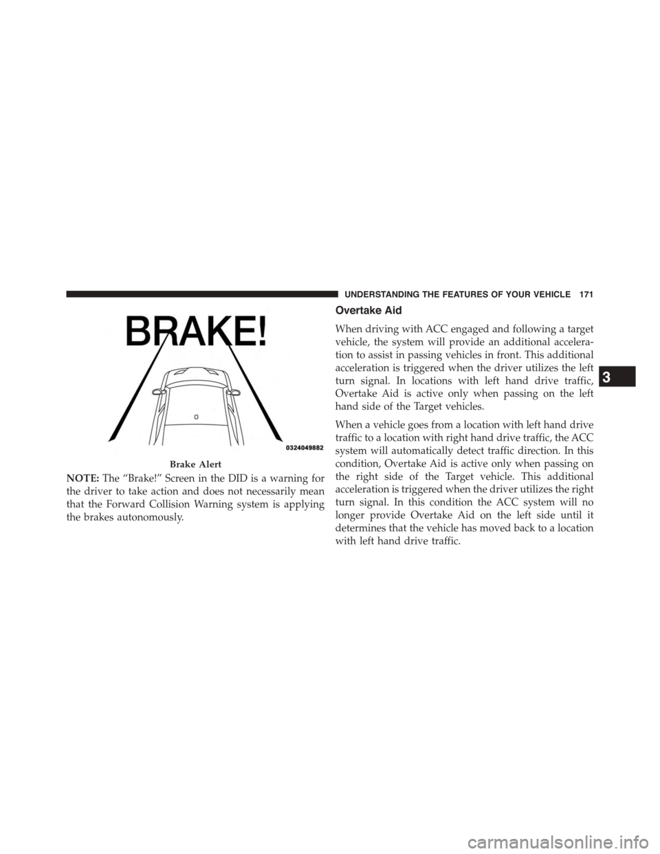
A Proximity Warning will alert the driver if ACC predicts
that its maximum braking level is not sufficient to
maintain the set distance. If this occurs, a visual alert
“BRAKE” will flash in the DID and a chime will sound
while ACC continues to apply its maximum braking
capacity.
170 UNDERSTANDING THE FEATURES OF YOUR VEHICLE
Page 173 of 603

NOTE:The “Brake!” Screen in the DID is a warning for
the driver to take action and does not necessarily mean
that the Forward Collision Warning system is applying
the brakes autonomously.
Overtake Aid
When driving with ACC engaged and following a target
vehicle, the system will provide an additional accelera-
tion to assist in passing vehicles in front. This additional
acceleration is triggered when the driver utilizes the left
turn signal. In locations with left hand drive traffic,
Overtake Aid is active only when passing on the left
hand side of the Target vehicles.
When a vehicle goes from a location with left hand drive
traffic to a location with right hand drive traffic, the ACC
system will automatically detect traffic direction. In this
condition, Overtake Aid is active only when passing on
the right side of the Target vehicle. This additional
acceleration is triggered when the driver utilizes the right
turn signal. In this condition the ACC system will no
longer provide Overtake Aid on the left side until it
determines that the vehicle has moved back to a location
with left hand drive traffic.
Brake Alert
3
UNDERSTANDING THE FEATURES OF YOUR VEHICLE 171
Page 179 of 603
Lane Changing
ACC may not detect a vehicle until it is completely in the
lane in which you are traveling. In the illustration shown,
ACC has not yet detected the vehicle changing lanes and
it may not detect the vehicle until it’s too late for the ACC
system to take action. ACC may not detect a vehicle until
it is completely in the lane. There may not be sufficient
distance to the lane-changing vehicle. Always be atten-
tive and ready to apply the brakes if necessary.
Lane Changing Example
3
UNDERSTANDING THE FEATURES OF YOUR VEHICLE 177
Page 180 of 603
Narrow Vehicles
Some narrow vehicles traveling near the outer edges of
the lane or edging into the lane are not detected until they
have moved fully into the lane. There may not be
sufficient distance to the vehicle ahead.
Stationary Objects And Vehicles
ACC does not react to stationary objects and stationary
vehicles. For example, ACC will not react in situations
where the vehicle you are following exits your lane and
the vehicle ahead is stopped in your lane. Always be
attentive and ready to apply the brakes if necessary.
Narrow Vehicle Example
Stationary Object And Stationary Vehicle Example
178 UNDERSTANDING THE FEATURES OF YOUR VEHICLE
Page 228 of 603

If the ABS light is on, the brake system should be serviced
as soon as possible to restore the benefits of Anti-Lock
Brakes. If the ABS light does not turn on when the
ignition switch is placed in the ON/RUN position, have
the light inspected by an authorized dealer.
6. Driver Information Display (DID) Area
The odometer display shows the total distance the ve-
hicle has been driven. The trip odometer shows indi-
vidual trip mileage.
NOTE:U.S. Federal regulations require that upon trans-
fer of vehicle ownership, the seller certify to the pur-
chaser the correct mileage that the vehicle has been
driven. If your odometer needs to be repaired or serviced,
the repair technician should leave the odometer reading
the same as it was before the repair or service. If he/she
cannot do so, then the odometer must be set at zero, and
a sticker must be placed in the door jamb stating what the
mileage was before the repair or service. It is a good idea
for you to make a record of the odometer reading before
the repair/service, so that you can be sure that it is
properly reset, or that the door jamb sticker is accurate if
the odometer must be reset at zero.
The DID features an interactive display, for further
information refer to “Driver Information Display (DID) ”.
226 UNDERSTANDING YOUR INSTRUMENT PANEL
Page 246 of 603

Braking Distance
When selected, this screen displays the vehicle’s braking
distance and the speed at which the brake pedal was
depressed.
•This feature will only function when applying the
brakes at speeds above 30 mph (48 km/h).
•Engaging the parking brake will disable this feature.
•The word “READY” will display when conditions are
met for the event to begin.
•The distance and speed measurements display while
the event is taking place.
•The distance measurement will be aborted if the brake
pedal is released before the vehicle comes to a com-
plete stop.
•The distance and speed measurements will continue to
display until theOKbutton is pushed.
•Pushing theOKbutton will clear the current run and
prepare the cluster to record a new run.
Current G-Force
When selected, this screen displays the current G-Force
(lateral and longitudinal) that displays the directions of
the forces.
Peak G-Force
When selected, this screen displays all four G-Force
values (two lateral and two longitudinal).
•When a force greater than zero is measured, the
display will update the value as it climbs. As the
G-Force falls, the peak forces will continue to display.
•Pushing theOKbutton will clear the peak force
values.
244 UNDERSTANDING YOUR INSTRUMENT PANEL