Page 278 of 726
The HomeLink® Universal Transceiver is disabled when
the Vehicle Security Alarm is active.
Troubleshooting Tips
If you are having trouble programming HomeLink®,
here are some of the most common solutions:
•Replace the battery in the original hand-held transmit-
ter.
•Push the LEARN button on the Garage Door Opener
to complete the training for a Rolling Code.
•Did you unplug the device for programming and
remember to plug it back in?
If you have any problems, or require assistance, please
call toll-free 1-800-355-3515 or, on the Internet at
HomeLink.com for information or assistance.
WARNING!
Vehicle exhaust contains carbon monoxide, a danger-
ous gas. Do not run your vehicle in the garage while
programming the transceiver. Exhaust gas can cause
serious injury or death.
WARNING!
Your motorized door or gate will open and close
while you are programming the universal trans-
ceiver. Do not program the transceiver if people, pets
or other objects are in the path of the door or gate.
Only use this transceiver with a garage door opener
that has a “stop and reverse” feature as required by
Federal safety standards. This includes most garage
door opener models manufactured after 1982. Do not
(Continued)
276 UNDERSTANDING THE FEATURES OF YOUR VEHICLE
Page 283 of 726
Sunroof Maintenance
Use only a non-abrasive cleaner and a soft cloth to clean
the glass panel.
Ignition Off Operation
For Vehicles Not Equipped With The Electronic Vehicle
Information Center (EVIC)
The power sunroof switch will remain active for 45
seconds after the ignition switch is turned to the LOCK
position. Opening either front door will cancel this
feature.
For Vehicles Equipped With The EVIC
The power sunroof switch will remain active for up to
approximately ten minutes after the ignition switch is
turned to the LOCK position. Opening either front door
will cancel this feature.
ELECTRICAL POWER OUTLETS — IF EQUIPPED
Two 12 Volt (13 Amp) power outlets are located on the
lower instrument panel, below the open storage bin. The
driver-side power outlet is controlled by the ignition
switch and the passenger-side power outlet is connected
directly to the battery. The driver-side power outlet will
also operate a conventional cigar lighter unit (if equipped
with an optional Smoker’s Package).
3
UNDERSTANDING THE FEATURES OF YOUR VEHICLE 281
Page 285 of 726
One outlet in the removable floor console (if equipped)
shares a fuse with the lower outlet in the instrument
panel and is also connected to the battery. Do not exceed
a maximum power of 160 Watts (13 Amps) shared
between the lower panel outlet and the removable floor
console outlet.
On vehicles equipped with the Super Console the power
outlets are located under the retractable cover. To access
the power outlets push down on the cover and slide it
toward the instrument panel.
Removable Console Outlet
Super Console Outlets
3
UNDERSTANDING THE FEATURES OF YOUR VEHICLE 283
Page 286 of 726
The outlet in the rear quarter panel near the liftgate and
the upper outlet in the instrument panel are both con-
trolled by the ignition switch. Each of these outlets can
support 160 Watts (13 Amps). Do not exceed 160 Watts
(13 Amps) for each of these outlets.
The power outlets include tethered caps, labeled with a
key or battery symbol indicating the power source. The
power outlet, located on the lower instrument panel, is
powered directly from the battery. Items plugged into
this power outlet may discharge the battery and/or
prevent the engine from starting.
Power Outlet Fuses
1 — M7 Fuse 20 A Yellow Power Outlet Center Seat (Opt) or withConsole Rear2 — M6 Fuse 20 A Yellow Cigar Lighter Instrument Panel or withConsole Front3 — M36 Fuse 20 A Yellow Power Outlet Instrument Panel orwith Console Center
284 UNDERSTANDING THE FEATURES OF YOUR VEHICLE
Page 287 of 726
WARNING!
To avoid serious injury or death:
•Only devices designed for use in this type of outlet
should be inserted into any 12 Volt outlet.
•Do not touch with wet hands.
•Close the lid when not in use and while driving the
vehicle.
•If this outlet is mishandled, it may cause an electric
shock and failure.
CAUTION!
•Many accessories that can be plugged in draw
power from the vehicle’s battery, even when not in
use (i.e., cellular phones, etc.). Eventually, if
plugged in long enough, the vehicle’s battery will
discharge sufficiently to degrade battery life and/or
prevent the engine from starting.
•Accessories that draw higher power (i.e., coolers,
vacuum cleaners, lights, etc.), will degrade the
battery even more quickly. Only use these intermit-
tently and with greater caution.
•After the use of high power draw accessories, or
long periods of the vehicle not being started (with
accessories still plugged in), the vehicle must be
driven a sufficient length of time to allow the
alternator to recharge the vehicle’s battery.
(Continued)
3
UNDERSTANDING THE FEATURES OF YOUR VEHICLE 285
Page 308 of 726
REAR WINDOW FEATURES
Rear Window Defroster
The rear window defroster button is located on
the climate control (Mode) knob. Press this button
to turn on the rear window defroster and the heated
outside mirrors (if equipped). An indicator in the button
will illuminate when the rear window defroster is on. The
rear window defroster automatically turns off after ap-
proximately 10 minutes. For an additional five minutes of
operation, press the button a second time.
NOTE:
•You can turn off the heated mirror feature at anytime
by pressing the rear window defroster switch a second
time.
•To prevent excessive battery drain, use the rear win-
dow defroster only when the engine is operating.
CAUTION!
Failure to follow these cautions can cause damage to
the heating elements:
•Use care when washing the inside of the rear
window. Do not use abrasive window cleaners on
the interior surface of the window. Use a soft cloth
and a mild washing solution, wiping parallel to the
heating elements. Labels can be peeled off after
soaking with warm water.
•Do not use scrapers, sharp instruments, or abrasive
window cleaners on the interior surface of the
window.
•Keep all objects a safe distance from the window.
306 UNDERSTANDING THE FEATURES OF YOUR VEHICLE
Page 343 of 726
•Remote start disabled — Start Vehicle to Reset
•Remote start active — Push Start Button
•Remote start active — Key to Run
•Wrong Key
•Damaged Key
•Key not programmed
•Vehicle Not in Park
•Key Left Vehicle
•Key Not Detected
•Press Brake Pedal and Push Button to Start
•Liftgate Ajar (chime will sound when vehicle starts
moving)
•Low Tire Pressure
•Service TPM System (refer to “Tire Pressure Monitor-
ing System” in “Starting And Operating”)
•Tire Pressure Screen With Low Tire(s) “Inflate Tire to
XX”
•Turn Signal On
•RKE Battery Low
•Service Keyless System
•Low Washer Fluid
•Oil Change Required
•Check Gascap
•Left Front Turn Signal Light Out
•Left Rear Turn Signal Light Out
•Right Front Turn Signal Light Out
•Right Rear Turn Signal Light Out
4
UNDERSTANDING YOUR INSTRUMENT PANEL 341
Page 393 of 726
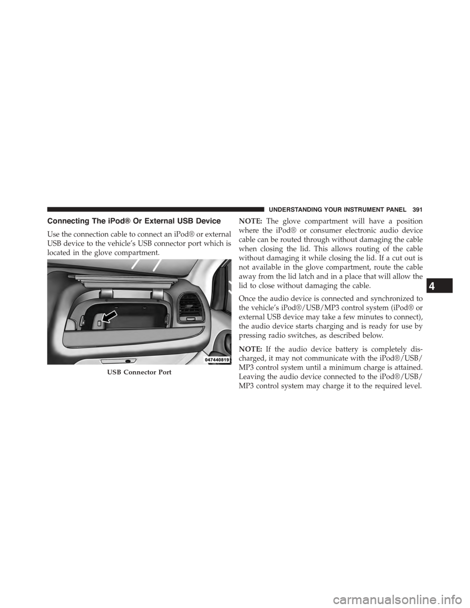
Connecting The iPod® Or External USB Device
Use the connection cable to connect an iPod® or external
USB device to the vehicle’s USB connector port which is
located in the glove compartment.
NOTE:The glove compartment will have a position
where the iPod® or consumer electronic audio device
cable can be routed through without damaging the cable
when closing the lid. This allows routing of the cable
without damaging it while closing the lid. If a cut out is
not available in the glove compartment, route the cable
away from the lid latch and in a place that will allow the
lid to close without damaging the cable.
Once the audio device is connected and synchronized to
the vehicle’s iPod®/USB/MP3 control system (iPod® or
external USB device may take a few minutes to connect),
the audio device starts charging and is ready for use by
pressing radio switches, as described below.
NOTE:If the audio device battery is completely dis-
charged, it may not communicate with the iPod®/USB/
MP3 control system until a minimum charge is attained.
Leaving the audio device connected to the iPod®/USB/
MP3 control system may charge it to the required level.
USB Connector Port
4
UNDERSTANDING YOUR INSTRUMENT PANEL 391