Page 181 of 726
Send Messages:
You can send messages using Uconnect® Phone. To send
a new message:
1. Push the Phonebutton.
2. After the “Ready” prompt and the following beep, say
“SMS Send” or “Send Message.”
3. You can either say the message you wish to send or
say “List Messages.” There are 20 preset messages.
To send a message, push the Voice Commandbut-
ton while the system is listing the message and say
“Send.” Uconnect® Phone will prompt you to say the
name or number of the person you wish to send the
message to.
List of Preset Messages:
1. Yes.
2. No.
3. Where are you?
4. I need more direction.
5. L O L.
6. Why?
7. I love you.
8. Call me.
9. Call me later.
10. Thanks.
11. See you in 15 minutes.
12. I am on my way.
13. I’ll be late.
14. Are you there yet?
3
UNDERSTANDING THE FEATURES OF YOUR VEHICLE 179
Page 206 of 726
NOTE:
•The head restraints should only be removed by quali-
fied technicians, for service purposes only. If either of
the head restraints require removal, see your autho-
rized dealer.
•In the event of deployment of an Active Head Re-
straint, refer to “Occupant Restraints/Resetting Active
Head Restraints (AHR)” in “Things To Know Before
Starting Your Vehicle” for further information.
WARNING!
•Do not place items over the top of the Active Head
Restraint, such as coats, seat covers or portable
DVD players. These items may interfere with the
operation of the Active Head Restraint in the event
of a collision and could result in serious injury or
death.
(Continued)
Active Head Restraint (Tilted)
204 UNDERSTANDING THE FEATURES OF YOUR VEHICLE
Page 227 of 726
equipped), and radio station preset settings. Your Remote
Keyless Entry (RKE) transmitters can also be pro-
grammed to recall the same positions when the UN-
LOCK button is pressed.
Your vehicle may have been delivered with two RKE
transmitters, one RKE transmitter can be linked to each of
the memory positions.
Programming The Memory Feature
NOTE:To create a new memory profile, perform the
following:
1. Cycle the vehicles ignition to the ON/RUN position
(Do not start the engine).
2. Adjust all memory profile settings to desired prefer-
ences (i.e., driver ’s seat, outside mirrors, adjustable
pedals [if equipped] and radio station presets).
3. Press and release the S (Set) button on the memory
switch.
Driver Memory Switch
3
UNDERSTANDING THE FEATURES OF YOUR VEHICLE 225
Page 251 of 726

NOTE:In order to ensure proper operation, the Elec-
tronic Speed Control System has been designed to shut
down if multiple Speed Control functions are operated at
the same time. If this occurs, the Electronic Speed Control
System can be reactivated by pushing the Electronic
Speed Control ON/OFF button and resetting the desired
vehicle set speed.
To Activate
Push the ON/OFF button. The Cruise Indicator Light in
the instrument cluster will illuminate. To turn the system
off, push the ON/OFF button a second time. The Cruise
Indicator Light will turn off. The system should be
turned off when not in use.
WARNING!
Leaving the Electronic Speed Control system on
when not in use is dangerous. You could accidentally
set the system or cause it to go faster than you want.
You could lose control and have an accident. Always
leave the system OFF when you are not using it.
To Set A Desired Speed
Turn the Electronic Speed Control ON. When the vehicle
has reached the desired speed, press the SET (-) button
and release. Release the accelerator and the vehicle will
operate at the selected speed.
NOTE:The vehicle should be traveling at a steady speed
and on level ground before pressing the SET (-) button.
3
UNDERSTANDING THE FEATURES OF YOUR VEHICLE 249
Page 289 of 726

This outlet can power cellular phones, electronics and
other low power devices requiring power up to
150 Watts. Certain high-end video games, such as Play-
station3 and XBox360 will exceed this power limit, as will
most power tools.
The power inverter is designed with built-in overload
protection. If the power rating of 150 Watts is exceeded,
the power inverter will automatically shut down. Once
the electrical device has been removed from the outlet,
the inverter should automatically reset. If the power
rating exceeds approximately 170 Watts, the power in-
verter may have to be reset manually. To reset the
inverter manually push the power inverter button OFF
and ON. To avoid overloading the circuit, check the
power ratings on electrical devices prior to using the
inverter.
WARNING!
To avoid serious injury or death:
•Do not insert any objects into the receptacles.
•Do not touch with wet hands.
•Close the lid when not in use.
•If this outlet is mishandled, it may cause an electric
shock and failure.
CUPHOLDERS
There are cupholders located throughout the interior. All
liners are removable for cleaning. Pull the flexible liner
from the cupholder drawer or tray starting at one edge
for easy removal. Refer to “Cleaning The Instrument
Panel Cupholders” in “Maintaining Your Vehicle” for
further information.
3
UNDERSTANDING THE FEATURES OF YOUR VEHICLE 287
Page 309 of 726

LOAD LEVELING SYSTEM — IF EQUIPPED
The automatic load leveling system will provide a level-
riding vehicle under most passenger and cargo loading
conditions.
A hydraulic pump contained within the shock absorbers
raises the rear of the vehicle to the correct height. It takes
approximately 1 mile (1.6 km) of driving for the leveling
to complete depending on road surface conditions.
If the leveled vehicle is not moved for approximately 15
hours, the leveling system will bleed itself down. The
vehicle must be driven to reset the system.
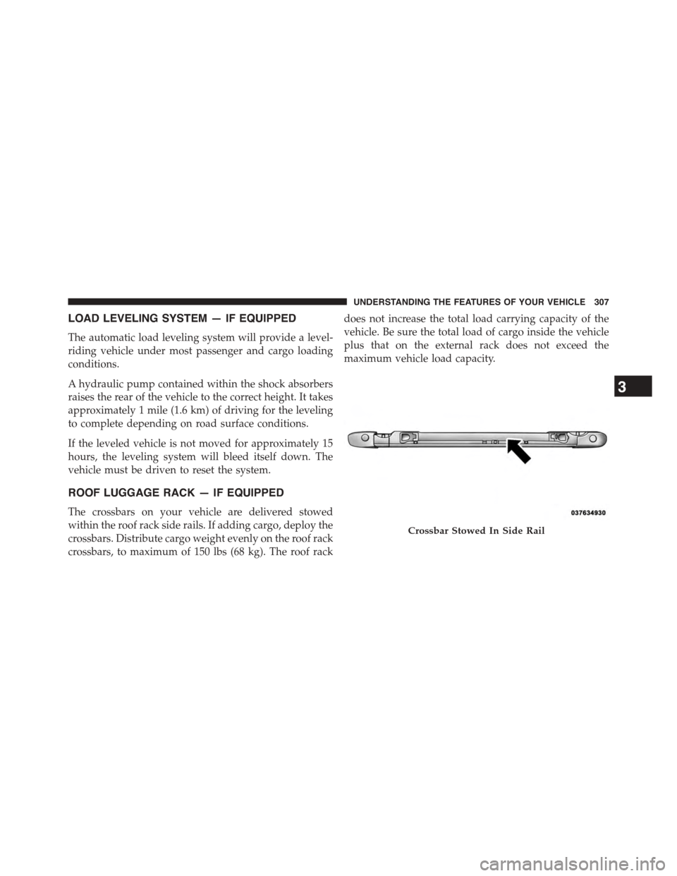
ROOF LUGGAGE RACK — IF EQUIPPED
The crossbars on your vehicle are delivered stowed
within the roof rack side rails. If adding cargo, deploy the
crossbars. Distribute cargo weight evenly on the roof rack
crossbars, to maximum of 150 lbs (68 kg). The roof rack
does not increase the total load carrying capacity of the
vehicle. Be sure the total load of cargo inside the vehicle
plus that on the external rack does not exceed the
maximum vehicle load capacity.
Crossbar Stowed In Side Rail
3
UNDERSTANDING THE FEATURES OF YOUR VEHICLE 307
Page 317 of 726
UNDERSTANDING YOUR INSTRUMENT PANEL
CONTENTS
!INSTRUMENT PANEL FEATURES..........320
!INSTRUMENT CLUSTER — BASE..........321
!INSTRUMENT CLUSTER — PREMIUM.......322
!INSTRUMENT CLUSTER DESCRIPTIONS.....323
!ELECTRONIC VEHICLE INFORMATION CENTER
(EVIC) — IF EQUIPPED..................337
▫Electronic Vehicle Information Center (EVIC)
Displays............................339
▫EVIC White Telltale Lights...............342
▫EVIC Amber Telltale Lights..............343
▫EVIC Red Telltale Lights................344
▫Oil Change Required...................346
▫Fuel Economy........................348
▫Vehicle Speed........................349
▫Trip Info...........................349
▫Tr i p A . . . . . . . . . . . . . . . . . . . . . . . . . . . ..349
▫Tr i p B . . . . . . . . . . . . . . . . . . . . . . . . . . . . ..350
▫Elapsed Time........................350
▫To Reset A Trip Function................350
▫Ti re P S I . . . . . . . . . . . . . . . . . . . . . . . . . . . ..350
4
Page 326 of 726

odometer needs to be repaired or serviced, the repair
technician should leave the odometer reading the same
as it was before the repair or service. If s/he cannot do so,
then the odometer must be set at zero, and a sticker must
be placed in the door jamb stating what the mileage was
before the repair or service. It is a good idea for you to
make a record of the odometer reading before the repair/
service, so that you can be sure that it is properly reset, or
that the door jamb sticker is accurate if the odometer
must be reset at zero.
This also displays Trip A and Trip B, DTE, MPG or
L/100km, OAT (Outside Air Temperature) information to
Base Cluster, use STEP and RESET button (on steering
wheel) to access or reset the display.
Message Display Area
When the appropriate conditions exist, the following
odometer messages will display:
door.............................Door Ajar
gATE..........................Liftgate Ajar
LoW tirE....................LowTirePressure
gASCAP......................Fuel Cap Fault
noFUSE..........................Fuse Fault
CHAngE OIL..............OilChange Required
LoCOOL.......................LowCoolant
NOTE:Some of the above warnings will be displayed in
the Electronic Vehicle Information Center Display Area
located in the instrument cluster.
Refer to ”Electronic Vehicle Information Center (EVIC) — If
Equipped” in this section for further information.
324 UNDERSTANDING YOUR INSTRUMENT PANEL