Page 279 of 399
Black plate (28,1)Chevrolet Malibu Owner Manual (GMNA-Localizing-U.S./Canada/Mexico-
7575972) - 2015 - crc - 4/1/14
10-28 Vehicle Care
6. Connect the electrical connector.
7. Replace the cap from the backof the headlamp assembly by
turning it clockwise.
8. For the driver side, reinstall the windshield washer bottle filler
neck by firmly pushing it straight
into the bottle. Ensure that the
filler neck clip engages into the
underhood electrical center
retainer.
HID Headlamp Assembly
The HID assembly has a high
intensity discharge (HID) high/low
beam, a DRL/parking lamp,
sidemarker lamp, and a turn signal
lamp on the headlamp assembly.
For replacement of the headlamp on
an HID assembly, contact your
dealer. See High Intensity
Discharge (HID) Lighting on
page 10-25.
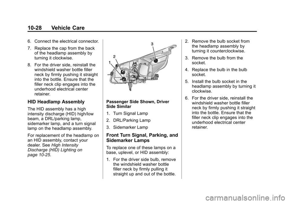
Passenger Side Shown, Driver
Side Similar
1. Turn Signal Lamp
2. DRL/Parking Lamp
3. Sidemarker Lamp
Front Turn Signal, Parking, and
Sidemarker Lamps
To replace one of these lamps on a
base, uplevel, or HID assembly:
1. For the driver side bulb, remove the windshield washer bottle
filler neck by firmly pulling it
straight up and out of the bottle. 2. Remove the bulb socket from
the headlamp assembly by
turning it counterclockwise.
3. Remove the bulb from the socket.
4. Replace the bulb in the bulb socket.
5. Install the bulb socket in the headlamp assembly by turning it
clockwise.
6. For the driver side, reinstall the windshield washer bottle filler
neck by firmly pushing it straight
into the bottle. Ensure that the
filler neck clip engages into the
underhood electrical center
retainer.
Page 280 of 399
Black plate (29,1)Chevrolet Malibu Owner Manual (GMNA-Localizing-U.S./Canada/Mexico-
7575972) - 2015 - crc - 4/1/14
Vehicle Care 10-29
Fog Lamps
To replace the front fog lamp bulb:
1. Remove the five access panelfasteners under the front fascia.
2. Lower the panel far enough to access the fog lamp bulb.
3. Remove the bulb by turning it
counterclockwise and pulling it
straight out of the assembly.
4. Disconnect the electrical connector from the fog lamp bulb
assembly.
5. Install the new bulb by turning it clockwise into the assembly.
6. Reverse Steps 1–4 to reinstall.
Taillamps, Turn Signal,
Stoplamps, and Back-Up
Lamps (LS and LT)
1. Back-Up Lamp
2. Taillamp
Trunk Deck Inboard Taillamp and
Back-Up Lamp
1. Open the trunk. See Trunk on
page 2-14.
2. Remove the push pins and pull back the trunk deck trim.
Page 281 of 399
Black plate (30,1)Chevrolet Malibu Owner Manual (GMNA-Localizing-U.S./Canada/Mexico-
7575972) - 2015 - crc - 4/1/14
10-30 Vehicle Care
3. Remove the bulb socket byturning counterclockwise and
pulling straight out.
4. Remove the bulb from the socket.
5. Install the new bulb in the bulb socket.
6. Install the bulb socket by turning clockwise.
7. Install the trunk deck trim.
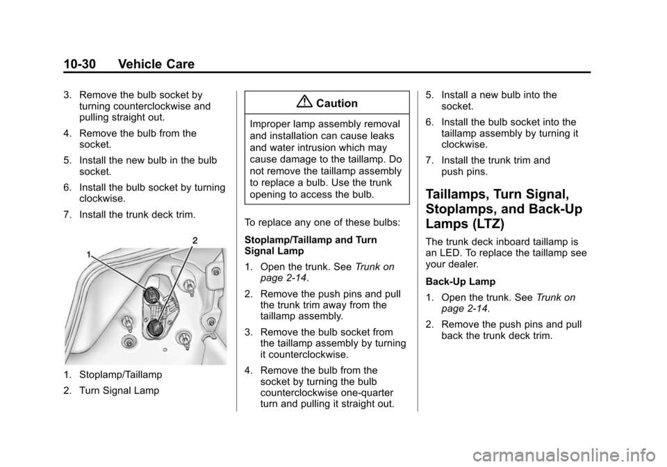
1. Stoplamp/Taillamp
2. Turn Signal Lamp
{Caution
Improper lamp assembly removal
and installation can cause leaks
and water intrusion which may
cause damage to the taillamp. Do
not remove the taillamp assembly
to replace a bulb. Use the trunk
opening to access the bulb.
To replace any one of these bulbs:
Stoplamp/Taillamp and Turn
Signal Lamp
1. Open the trunk. See Trunk on
page 2-14.
2. Remove the push pins and pull the trunk trim away from the
taillamp assembly.
3. Remove the bulb socket from the taillamp assembly by turning
it counterclockwise.
4. Remove the bulb from the socket by turning the bulb
counterclockwise one-quarter
turn and pulling it straight out. 5. Install a new bulb into the
socket.
6. Install the bulb socket into the taillamp assembly by turning it
clockwise.
7. Install the trunk trim and push pins.
Taillamps, Turn Signal,
Stoplamps, and Back-Up
Lamps (LTZ)
The trunk deck inboard taillamp is
an LED. To replace the taillamp see
your dealer.
Back-Up Lamp
1. Open the trunk. See Trunk on
page 2-14.
2. Remove the push pins and pull back the trunk deck trim.
Page 282 of 399
Black plate (31,1)Chevrolet Malibu Owner Manual (GMNA-Localizing-U.S./Canada/Mexico-
7575972) - 2015 - crc - 4/1/14
Vehicle Care 10-31
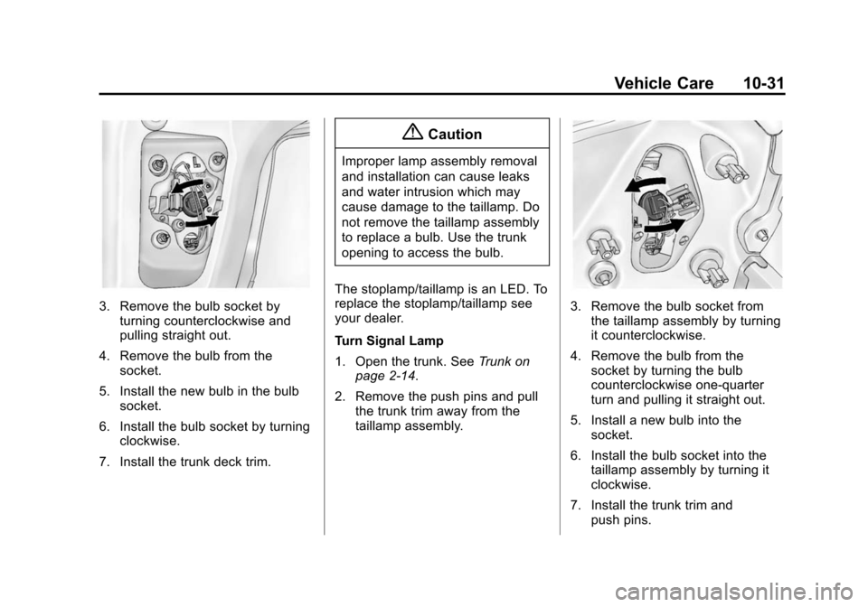
3. Remove the bulb socket byturning counterclockwise and
pulling straight out.
4. Remove the bulb from the socket.
5. Install the new bulb in the bulb socket.
6. Install the bulb socket by turning clockwise.
7. Install the trunk deck trim.
{Caution
Improper lamp assembly removal
and installation can cause leaks
and water intrusion which may
cause damage to the taillamp. Do
not remove the taillamp assembly
to replace a bulb. Use the trunk
opening to access the bulb.
The stoplamp/taillamp is an LED. To
replace the stoplamp/taillamp see
your dealer.
Turn Signal Lamp
1. Open the trunk. See Trunk on
page 2-14.
2. Remove the push pins and pull the trunk trim away from the
taillamp assembly.
3. Remove the bulb socket fromthe taillamp assembly by turning
it counterclockwise.
4. Remove the bulb from the socket by turning the bulb
counterclockwise one-quarter
turn and pulling it straight out.
5. Install a new bulb into the socket.
6. Install the bulb socket into the taillamp assembly by turning it
clockwise.
7. Install the trunk trim and push pins.
Page 283 of 399
Black plate (32,1)Chevrolet Malibu Owner Manual (GMNA-Localizing-U.S./Canada/Mexico-
7575972) - 2015 - crc - 4/1/14
10-32 Vehicle Care
License Plate Lamp
To replace one of these bulbs:
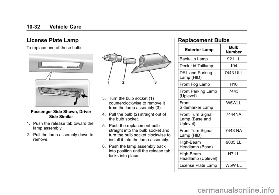
Passenger Side Shown, DriverSide Similar
1. Push the release tab toward the lamp assembly.
2. Pull the lamp assembly down to remove.
3. Turn the bulb socket (1)counterclockwise to remove it
from the lamp assembly (3).
4. Pull the bulb (2) straight out of the bulb socket.
5. Push the replacement bulb straight into the bulb socket and
turn the bulb socket clockwise to
install it into the lamp assembly.
6. Push the lamp assembly back into position until the release tab
locks into place.
Replacement Bulbs
Exterior Lamp Bulb
Number
Back-Up Lamp 921 LL
Deck Lid Taillamp 194
DRL and Parking
Lamp (HID) 7443 ULL
Front Fog Lamp H10
Front Parking Lamp
(Uplevel) 7443
Front
Sidemarker Lamp W5WLL
Front Turn Signal
Lamp (Base and
Uplevel) 7444NA
Front Turn Signal
Lamp (HID) 7443 NA
High-Beam
Headlamp (Base) 9005 LL
High-Beam
Headlamp (Uplevel) H7 LL
License Plate Lamp W5W LL
Page 284 of 399
Black plate (33,1)Chevrolet Malibu Owner Manual (GMNA-Localizing-U.S./Canada/Mexico-
7575972) - 2015 - crc - 4/1/14
Vehicle Care 10-33
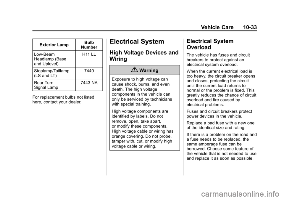
Exterior LampBulb
Number
Low-Beam
Headlamp (Base
and Uplevel) H11 LL
Stoplamp/Taillamp
(LS and LT) 7440
Rear Turn
Signal Lamp 7443 NA
For replacement bulbs not listed
here, contact your dealer.Electrical System
High Voltage Devices and
Wiring
{Warning
Exposure to high voltage can
cause shock, burns, and even
death. The high voltage
components in the vehicle can
only be serviced by technicians
with special training.
High voltage components are
identified by labels. Do not
remove, open, take apart,
or modify these components.
High voltage cable or wiring has
orange covering. Do not probe,
tamper with, cut, or modify high
voltage cable or wiring.
Electrical System
Overload
The vehicle has fuses and circuit
breakers to protect against an
electrical system overload.
When the current electrical load is
too heavy, the circuit breaker opens
and closes, protecting the circuit
until the current load returns to
normal or the problem is fixed. This
greatly reduces the chance of circuit
overload and fire caused by
electrical problems.
Fuses and circuit breakers protect
power devices in the vehicle.
Replace a bad fuse with a new one
of the identical size and rating.
If there is a problem on the road and
a fuse needs to be replaced, the
same amperage fuse can be
borrowed. Choose some feature of
the vehicle that is not needed to use
and replace it as soon as possible.
Page 290 of 399
Black plate (39,1)Chevrolet Malibu Owner Manual (GMNA-Localizing-U.S./Canada/Mexico-
7575972) - 2015 - crc - 4/1/14
Vehicle Care 10-39
Instrument Panel Fuse Block
The vehicle may not be equipped
with all of the fuses, relays, and
features shown. Fuses Usage
1 Steering Wheel Controls Backlight
2 Right Rear Turn Signal, Left Mirror
Turn Signal, Left
Front Turn Signal,
Door Locks Fuses
Usage
3 Left Stoplamp, Left DRL Lamp,
Headlamp Control,
Right Taillamp, Right
Park/Sidemarker
Lamps, Right Mirror
Turn, Right Front
Turn Signals
4 Radio
5 OnStar (If Equipped)
6 Front Accessory Power Outlet
7 Console Bin Power Outlet Fuses
Usage
8 License Plate Lamp, Center
High-Mounted
Stoplamp, Rear Fog
Lamps, Right Front
Park/Sidemarker
Lamps, LED
Indicator Dim,
Washer Pump, Right
Stoplamp, Trunk
Release
9 Left Low-Beam Headlamp, DRL
10 Body Control Module 8 (J-Case
Fuse), Power Locks
11 Front Heater Ventilation Air
Conditioning/Blower
(J-Case Fuse)
Page 304 of 399
Black plate (53,1)Chevrolet Malibu Owner Manual (GMNA-Localizing-U.S./Canada/Mexico-
7575972) - 2015 - crc - 4/1/14
Vehicle Care 10-53
.Operating electronic devices or
being near facilities using radio
wave frequencies similar to the
TPMS could cause the TPMS
sensors to malfunction.
If the TPMS is not functioning
properly it cannot detect or signal a
low tire condition. See your dealer
for service if the TPMS malfunction
light and DIC message comes on
and stays on.
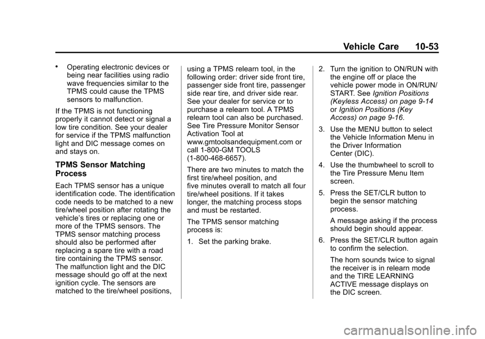
TPMS Sensor Matching
Process
Each TPMS sensor has a unique
identification code. The identification
code needs to be matched to a new
tire/wheel position after rotating the
vehicle’s tires or replacing one or
more of the TPMS sensors. The
TPMS sensor matching process
should also be performed after
replacing a spare tire with a road
tire containing the TPMS sensor.
The malfunction light and the DIC
message should go off at the next
ignition cycle. The sensors are
matched to the tire/wheel positions, using a TPMS relearn tool, in the
following order: driver side front tire,
passenger side front tire, passenger
side rear tire, and driver side rear.
See your dealer for service or to
purchase a relearn tool. A TPMS
relearn tool can also be purchased.
See Tire Pressure Monitor Sensor
Activation Tool at
www.gmtoolsandequipment.com or
call 1-800-GM TOOLS
(1-800-468-6657).
There are two minutes to match the
first tire/wheel position, and
five minutes overall to match all four
tire/wheel positions. If it takes
longer, the matching process stops
and must be restarted.
The TPMS sensor matching
process is:
1. Set the parking brake.
2. Turn the ignition to ON/RUN with
the engine off or place the
vehicle power mode in ON/RUN/
START. See Ignition Positions
(Keyless Access) on page 9-14
or Ignition Positions (Key
Access) on page 9-16.
3. Use the MENU button to select the Vehicle Information Menu in
the Driver Information
Center (DIC).
4. Use the thumbwheel to scroll to the Tire Pressure Menu Item
screen.
5. Press the SET/CLR button to begin the sensor matching
process.
A message asking if the process
should begin should appear.
6. Press the SET/CLR button again to confirm the selection.
The horn sounds twice to signal
the receiver is in relearn mode
and the TIRE LEARNING
ACTIVE message displays on
the DIC screen.