2015 BMW X4 Rear
[x] Cancel search: RearPage 64 of 253
securely against the backrest. If possible, ad‐
just the backrest tilt for all affected backrests
and correctly adjust the seats. Make sure that
seats and backrests are securely engaged. If
possible, adjust the height of the head re‐
straints or remove them.◀
Installing child restraint
systems
Information Pay attention to the specifications of the child
restraint system manufacturer when selecting,
installing, and using child restraint systems.
WARNING
The stability of the child restraint system
is limited or compromised with incorrect seat
adjustment or improper installation of the child
seat. There is risk of injuries or danger to life.
Make sure that the child restraint system fits
securely against the backrest. If possible, ad‐
just the backrest tilt for all affected backrests
and correctly adjust the seats. Make sure that
seats and backrests are securely engaged. If
possible, adjust the height of the head re‐
straints or remove them.◀
On the front passenger seat
Deactivating airbags WARNING
Active front-seat passenger airbags can
injure a child in a child restraint system when
the airbags are activated. There is risk of inju‐
ries. Make sure that the front-seat passenger
airbags are deactivated and that the PASSEN‐
GER AIRBAG OFF indicator lamp lights up.◀
After installing a child restraint system in the
front passenger seat, make sure that the front,
knee and side airbags on the front passenger
side are deactivated.Deactivate the front-seat passenger airbags
automatically, refer to page 105.
Seat position and height
Before installing a child restraint system, move
the front passenger seat as far back as possi‐
ble and adjust its height to the highest and
thus best possible position for the belt and to
offer optimal protection in the event of an acci‐
dent.
If the upper anchorage of the safety belt is lo‐
cated in front of the belt guide of the child seat,
move the passenger seat carefully forward un‐
til the best possible belt guide position is
reached.
Backrest width Adjustable backrest width: before installing a
child restraint system in the front passenger
seat, open the backrest width completely. Do
not change the backrest width again and do
not call up a memory position.
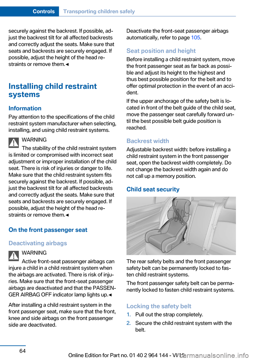
Child seat security
The rear safety belts and the front passenger
safety belt can be permanently locked to fas‐
ten child restraint systems.
The front passenger safety belt can be perma‐
nently locked to fasten child restraint systems.
Locking the safety belt
1.Pull out the strap completely.2.Secure the child restraint system with the
belt.Seite 64ControlsTransporting children safely64
Online Edition for Part no. 01 40 2 964 144 - VI/15
Page 65 of 253
3.Allow the strap to be pulled in and pull it
tight against the child restraint system.
The safety belt is locked.
Unlocking the safety belt
1.Unbuckle the belt buckle.2.Remove the child restraint system.3.Allow the strap to be pulled in completely.
LATCH child restraint system
Information
LATCH: Lower Anchors and Tether for Chil‐
dren.
Pay attention to the operating and safety infor‐
mation of the child restraint system manufac‐
turer when installing and using LATCH child
restraint fixing system.
Mounts for the lower LATCH anchors The lower anchors may be used to attach the
CRS to the vehicle seat up to a combined child
and CRS weight of 65 lb/30 kg when the child
is restrained by the internal harnesses.
Information WARNING
If the LATCH child restraint fixing sys‐
tems are not correctly engaged, the protective
effect of the LATCH child restraint fixing sys‐
tem can be limited. There is risk of injuries or
danger to life. Make sure that the lower an‐
chors are securely engaged and that the
LATCH child restraint fixing system fits se‐
curely against the backrest.◀
Position The corresponding symbol shows the
mounts for the lower LATCH anchors.
Seats equipped with lower anchors are
marked with a pair, 2, of LATCH sym‐
bols. It is not recommended to use the
inner lower anchors of standard outer
LATCH positions to fasten a child restraintsystem on the middle seat. Use the vehicle
seat belt instead for the middle seat.
Before installing LATCH child
restraint systems
Pull the belt away from the area of the child re‐straint system.
Assembly of LATCH child restraint
systems1.Install child restraint system, see manufac‐
turer's information.2.Ensure that both LATCH anchors are prop‐
erly connected.
Child restraint fixing system with a
tether strap
Mounting points The respective symbol shows the an‐
chor for the upper retaining strap.
Seats with an upper Top Tether are
marked with this symbol. It can be found on
the rear seat backrest or the rear window shelf.
Information CAUTION
The mounting points for the upper re‐
taining straps of child restraint systems are
only provided for these retaining straps. When
other objects are mounted, the anchors can be
damaged. There is risk of property damage.
Seite 65Transporting children safelyControls65
Online Edition for Part no. 01 40 2 964 144 - VI/15
Page 66 of 253
Only mount child restraint systems to the up‐
per retaining straps.◀
Retaining strap guide WARNING
If the upper retaining strap is incorrectly
used for the child restraint system, the protec‐
tive effect can be reduced. There is risk of inju‐
ries. Make sure that the upper retaining strap is
not guided across sharp edges and without
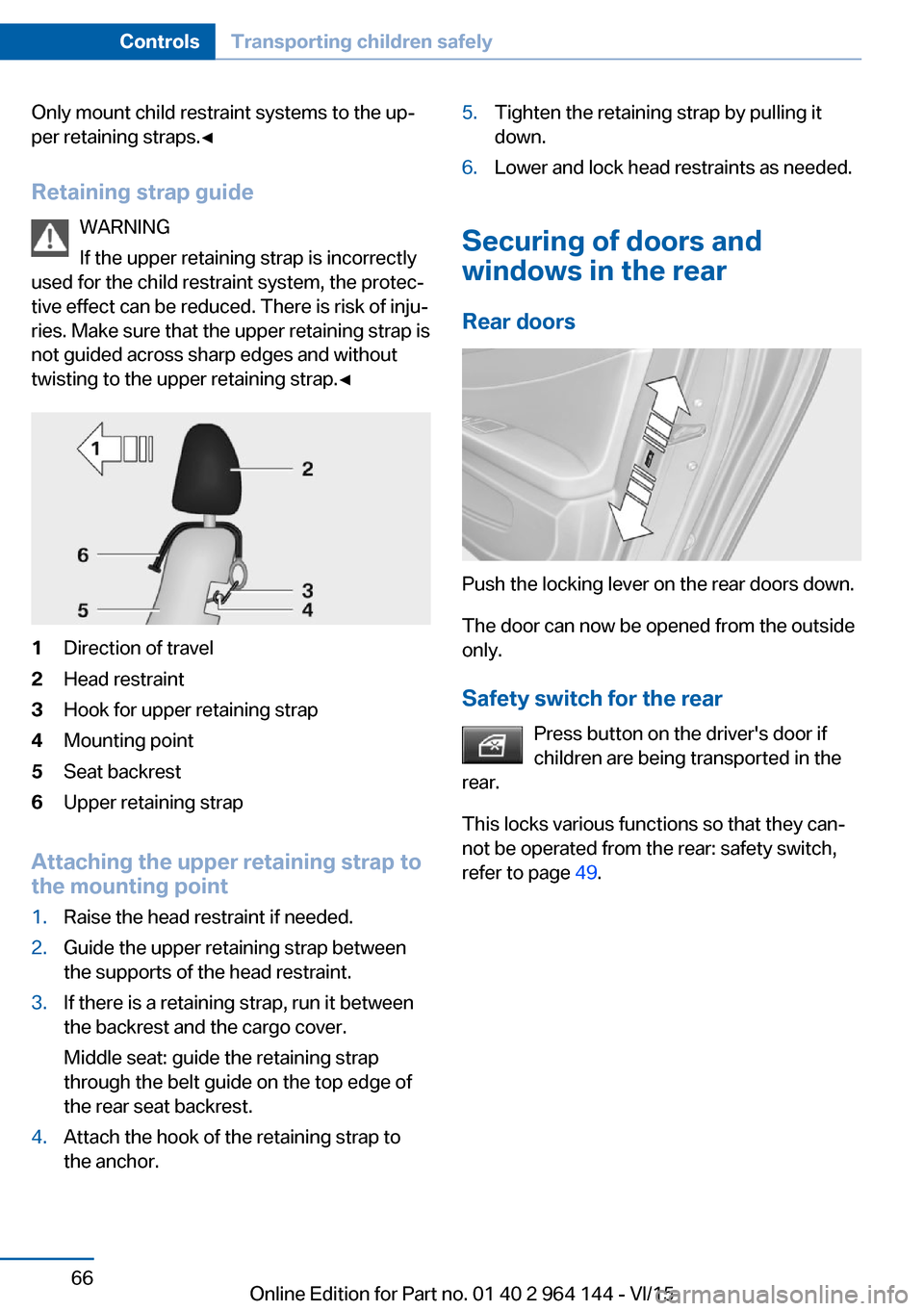
twisting to the upper retaining strap.◀1Direction of travel2Head restraint3Hook for upper retaining strap4Mounting point5Seat backrest6Upper retaining strap
Attaching the upper retaining strap to
the mounting point
1.Raise the head restraint if needed.2.Guide the upper retaining strap between
the supports of the head restraint.3.If there is a retaining strap, run it between
the backrest and the cargo cover.
Middle seat: guide the retaining strap
through the belt guide on the top edge of
the rear seat backrest.4.Attach the hook of the retaining strap to
the anchor.5.Tighten the retaining strap by pulling it
down.6.Lower and lock head restraints as needed.
Securing of doors and
windows in the rear
Rear doors
Push the locking lever on the rear doors down.
The door can now be opened from the outside
only.
Safety switch for the rear Press button on the driver's door if
children are being transported in the
rear.
This locks various functions so that they can‐
not be operated from the rear: safety switch,
refer to page 49.
Seite 66ControlsTransporting children safely66
Online Edition for Part no. 01 40 2 964 144 - VI/15
Page 75 of 253

Switching on
The lever automatically returns to its initial po‐
sition when released.
▷Normal wiper speed: tap up once.
The wipers switch to intermittent operation
when the vehicle is stationary.▷Fast wiper speed: tap up twice or tap once
beyond the resistance point.
Wipers change to normal speed when ve‐
hicle comes to standstill.
Switch off and brief wipe
The lever automatically returns to its initial po‐
sition when released.
▷Single wipe: press down once.▷To switch off from normal wiper speed:
press down once.▷To switch off from fast wiper speed: press
down twice.
Interval mode or rain sensor
The concept Without the rain sensor, the frequency of the
wiper operation is preset.
The rain sensor automatically controls the time
between wipes depending on the intensity of the rainfall. The sensor is located on the wind‐
shield, directly behind the interior rearview mir‐
ror.
Activating/deactivating
Press button on the wiper lever.
Wiping is started. If the vehicle is equipped
with a rain sensor: LED in wiper lever lights up.
When wipers are frozen to windshield, wiper
operation is deactivated.
CAUTION
If the rain sensor is activated, the wipers
can accidentally start moving in car washes.
There is risk of property damage. Deactivate
the rain sensor in car washes.◀
Setting the frequency or sensitivity of
the rain sensor
Turn the thumbwheel to adjust the frequency
or sensitivity of the rain sensor.
Up: short interval or high sensitivity of the rain
sensor.
Seite 75DrivingControls75
Online Edition for Part no. 01 40 2 964 144 - VI/15
Page 79 of 253

Activating the M/S manual mode1.Press the selector lever to the left out of
selector lever position D.2.Push the selector lever forward or pull it
backward.
Manual mode becomes active and the gear is
changed.
The engaged gear is displayed in the instru‐
ment cluster, e.g., M1.
If the situation requires, the Steptronic trans‐
mission continues to shift automatically.
Example: once maximum engine speed is at‐
tained, M/S manual mode is automatically up‐
shifted as needed.
Switching to manual mode
▷To shift down: press the selector lever for‐
ward.▷To shift up: pull the selector lever rear‐
wards.
Gears will only be shifted at appropriate engine
and road speeds, for example downshifting is
not possible if the engine speed is too high.
The selected gear is briefly displayed in the in‐
strument cluster, followed by the currently se‐
lected gear.
Steptronic Sport transmission:
prevent automatic upshifting in M/S
manual mode
The Steptronic Sport transmission does not
automatically upshift in M/S manual mode
once the maximum speed is reached, if one of
the following conditions is met:
▷DSC deactivated.▷TRACTION activated.▷SPORT+ activated.
In addition, there is no downshift for kickdown.
With the respective transmission version, the
lowest possible gear can be selected by simul‐
taneously operating the kickdown and the left
shift paddle. However, this effect is not pro‐
duced via the shift paddles when switching
briefly from selector lever position D to manual
mode.
Ending the sport program/manual
mode
Push the selector lever to the right.
D is displayed in the instrument cluster.
Shift paddles
The shift paddles on the steering wheel allow
you to shift gears quickly while keeping both
hands on the steering wheel.
▷Shift up: briefly pull right shift paddle.▷Shift down: briefly pull left shift paddle.▷With the respective transmission version,
the lowest possible gear can be selected
by pulling and holding the left shift paddle.
Gears will only be shifted at appropriate engine
and road speeds, for example downshifting is
not possible if the engine speed is too high.
The selected gear is briefly displayed in the in‐
strument cluster, followed by the current gear.
If the shift paddles on the steering wheel are
used to shift gears in automatic mode, the
transmission temporarily switches to manual
mode.
If the selector lever is still in selector lever po‐
sition D with the respective transmission ver‐
sion, it is possible to switch back into the auto‐
matic mode:
▷Pull and hold right shift paddle.
orSeite 79DrivingControls79
Online Edition for Part no. 01 40 2 964 144 - VI/15
Page 90 of 253
On vehicles without a gear shift indicator, the
engaged gear is displayed.
Steptronic transmission: displaysExampleDescriptionFuel efficient gear is set.Shift into fuel efficient gear.
Speed limit detection
The concept
Speed limit detection
Speed limit detection shows the current maxi‐
mum permitted speed in the instrument clus‐
ter. The camera in the area of the interior rear‐
view mirror detects traffic signs at the edge of
the road as well as variable overhead sign
posts. Traffic signs with extra symbols for wet
road conditions, etc. are also detected and
compared with the vehicle's onboard data,
such as for the rain sensor, and will be dis‐
played depending on the situation. The system
takes into account the information stored in
the navigation system and also displays speed
limits present on routes without signs.
Information WARNING
The system does not relieve from the
personal responsibility to correctly assess visi‐
bility and traffic situation. There is risk of an ac‐
cident. Adjust the driving style to the traffic
conditions. Watch traffic closely and actively
interfere in the respective situations.◀
Overview
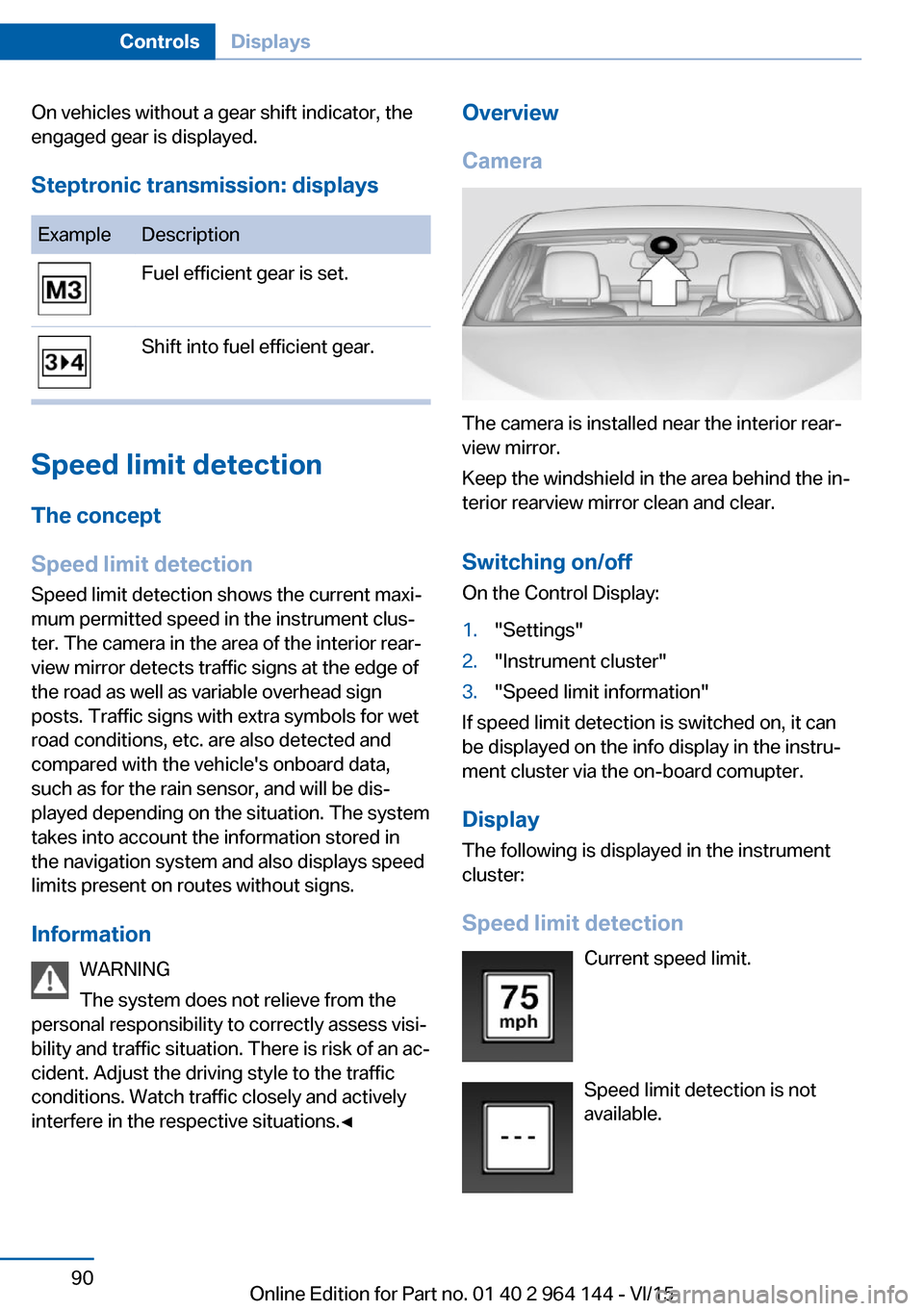
Camera
The camera is installed near the interior rear‐
view mirror.
Keep the windshield in the area behind the in‐
terior rearview mirror clean and clear.
Switching on/offOn the Control Display:
1."Settings"2."Instrument cluster"3."Speed limit information"
If speed limit detection is switched on, it can
be displayed on the info display in the instru‐
ment cluster via the on-board comupter.
Display The following is displayed in the instrument
cluster:
Speed limit detection Current speed limit.
Speed limit detection is not available.
Seite 90ControlsDisplays90
Online Edition for Part no. 01 40 2 964 144 - VI/15
Page 91 of 253

Speed limit detection can also be displayed in
the Head-up Display.
System limits The system may not be fully functional and
may provide incorrect information in the fol‐
lowing situations:▷In heavy fog, rain or snowfall.▷When signs are concealed by objects.▷When driving very close to the vehicle in
front of you.▷When driving toward bright lights.▷When the windshield behind the interior
rearview mirror is fogged over, dirty or cov‐
ered by a sticker, etc.▷In the event of incorrect detection by the
camera.▷If the speed limits stored in the navigation
system are incorrect.▷In areas not covered by the navigation sys‐
tem.▷When roads differ from the navigation,
such as due to changes in road routing.▷When passing buses or trucks with a
speed sticker.▷If the traffic signs are non-conforming.▷During calibration of the camera immedi‐
ately after vehicle delivery.
Selection lists in the
instrument cluster
The concept Depending on your vehicle's optional features,
the following can be displayed or operated us‐
ing the buttons and the thumbwheel on the
steering wheel as well as the displays in the in‐
strument cluster and the Head-up Display:
▷Current audio source.▷Redial phone feature.▷Turn on voice activation system.
Display
Depending on your vehicle's optional features,
the list in the instrument cluster can differ from
the illustration shown.
Activating a list and adjusting the
setting
On the right side of the steering wheel, turn
the thumbwheel to activate the corresponding
list.
Using the thumbwheel, select the desired set‐
ting and confirm it by pushing the thumbwheel.
Seite 91DisplaysControls91
Online Edition for Part no. 01 40 2 964 144 - VI/15
Page 100 of 253
E. g. the sensors are unable to detect fog or
hazy weather. To avoid safety risks under
these conditions, you should always switch on
the lights manually.
Daytime running lights Position of switch:
, ,
The daytime running lights light up when the
ignition is switched on. After the ignition is
switched off, the parking lights light up in posi‐
tion
.
Activating/deactivating In some countries, daytime running lights are
mandatory, so it may not be possible to deacti‐
vate the daytime running lights.
On the Control Display:
1."Settings"2."Lighting"3."Daytime running lamps"
Settings are stored for the profile currently
used.
Adaptive Light Control
The concept Adaptive Light Control is a variable headlight
control system that enables dynamic illumina‐
tion of the road surface.
Depending on the steering angle and other pa‐
rameters, the light from the headlight follows
the course of the road.
Activating Position of switch
with the ignition
switched on.
To avoid blinding oncoming traffic, the Adap‐
tive Light Control does not swivel to the driv‐
er's side when the vehicle is at a standstill.
The turning lights are automatically switched
on depending on the steering angle or the use
of turn signals.
When driving in reverse, the turning lights may
be automatically switched on regardless of the
steering angle.
Self-leveling headlights The self-leveling headlights compensate for
acceleration and braking operations in order
not to blind the oncoming traffic and to achieve
optimum illumination of the roadway.
Malfunction A Check Control message is displayed.
Adaptive Light Control is malfunctioning or has
failed. Have the system checked as soon as
possible.
High-beam Assistant
The concept When the low beams are activated, this system
automatically switches the high beams on and
off or suppresses the light in the areas that
blind oncoming traffic. The procedure is con‐
trolled by a camera on the front of the interior
rearview mirror. The assistant ensures that the
high beams are activated whenever the traffic
situation allows. The driver can intervene at
any time and switch the high beams on and off
as usual. In the low speed range, the high
beams are not switched on by the system.Seite 100ControlsLights100
Online Edition for Part no. 01 40 2 964 144 - VI/15