2015 BMW X4 Rear
[x] Cancel search: RearPage 221 of 253
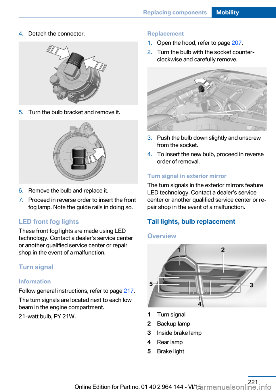
4.Detach the connector.5.Turn the bulb bracket and remove it.6.Remove the bulb and replace it.7.Proceed in reverse order to insert the front
fog lamp. Note the guide rails in doing so.
LED front fog lights
These front fog lights are made using LED
technology. Contact a dealer’s service center
or another qualified service center or repair
shop in the event of a malfunction.
Turn signal
Information
Follow general instructions, refer to page 217.
The turn signals are located next to each low
beam in the engine compartment.
21-watt bulb, PY 21W.
Replacement1.Open the hood, refer to page 207.2.Turn the bulb with the socket counter‐
clockwise and carefully remove.3.Push the bulb down slightly and unscrew
from the socket.4.To insert the new bulb, proceed in reverse
order of removal.
Turn signal in exterior mirror
The turn signals in the exterior mirrors feature
LED technology. Contact a dealer’s service
center or another qualified service center or re‐
pair shop in the event of a malfunction.
Tail lights, bulb replacement
Overview
1Turn signal2Backup lamp3Inside brake lamp4Rear lamp5Brake lightSeite 221Replacing componentsMobility221
Online Edition for Part no. 01 40 2 964 144 - VI/15
Page 222 of 253
Bulb replacement, exterior tail lightsGeneral information
Follow general instructions, refer to page 217.
Turn signal: 21-watt bulb, P21W.
Outer brake lamp: 24-watt bulb, PW24W.
The rear lamp features LED technology. Con‐
tact a dealer’s service center or another quali‐
fied service center or repair shop in the event
of a malfunction.
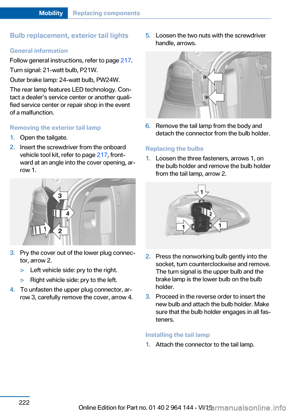
Removing the exterior tail lamp1.Open the tailgate.2.Insert the screwdriver from the onboard
vehicle tool kit, refer to page 217, front‐
ward at an angle into the cover opening, ar‐
row 1.3.Pry the cover out of the lower plug connec‐
tor, arrow 2.▷Left vehicle side: pry to the right.▷Right vehicle side: pry to the left.4.To unfasten the upper plug connector, ar‐
row 3, carefully remove the cover, arrow 4.5.Loosen the two nuts with the screwdriver
handle, arrows.6.Remove the tail lamp from the body and
detach the connector from the bulb holder.
Replacing the bulbs
1.Loosen the three fasteners, arrows 1, on
the bulb holder and remove the bulb holder
from the tail lamp, arrow 2.2.Press the nonworking bulb gently into the
socket, turn counterclockwise and remove.
The turn signal is the upper bulb and the
brake lamp is the lower bulb on the bulb
holder.3.Proceed in the reverse order to insert the
new bulb and attach the bulb holder. Make
sure that the bulb holder engages in all fas‐
teners.
Installing the tail lamp
1.Attach the connector to the tail lamp.Seite 222MobilityReplacing components222
Online Edition for Part no. 01 40 2 964 144 - VI/15
Page 223 of 253
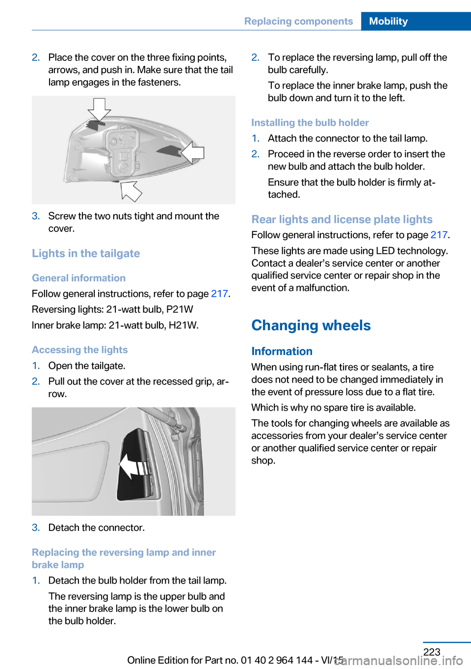
2.Place the cover on the three fixing points,
arrows, and push in. Make sure that the tail
lamp engages in the fasteners.3.Screw the two nuts tight and mount the
cover.
Lights in the tailgate
General information
Follow general instructions, refer to page 217.
Reversing lights: 21-watt bulb, P21W
Inner brake lamp: 21-watt bulb, H21W.
Accessing the lights
1.Open the tailgate.2.Pull out the cover at the recessed grip, ar‐
row.3.Detach the connector.
Replacing the reversing lamp and inner
brake lamp
1.Detach the bulb holder from the tail lamp.
The reversing lamp is the upper bulb and
the inner brake lamp is the lower bulb on
the bulb holder.2.To replace the reversing lamp, pull off the
bulb carefully.
To replace the inner brake lamp, push the
bulb down and turn it to the left.
Installing the bulb holder
1.Attach the connector to the tail lamp.2.Proceed in the reverse order to insert the
new bulb and attach the bulb holder.
Ensure that the bulb holder is firmly at‐
tached.
Rear lights and license plate lights
Follow general instructions, refer to page 217.
These lights are made using LED technology.
Contact a dealer’s service center or another
qualified service center or repair shop in the
event of a malfunction.
Changing wheels
Information When using run-flat tires or sealants, a tire
does not need to be changed immediately in
the event of pressure loss due to a flat tire.
Which is why no spare tire is available.
The tools for changing wheels are available as
accessories from your dealer’s service center
or another qualified service center or repair
shop.
Seite 223Replacing componentsMobility223
Online Edition for Part no. 01 40 2 964 144 - VI/15
Page 229 of 253
Switch all Intelligent Safety systems off prior to
tow-starting/towing.◀
Steptronic transmission: transporting
your vehicle
Information CAUTION
The vehicle can be damaged when tow‐
ing the vehicle with a single lifted axle. There is
risk of property damage. The vehicle should
only be transported on a loading platform.◀
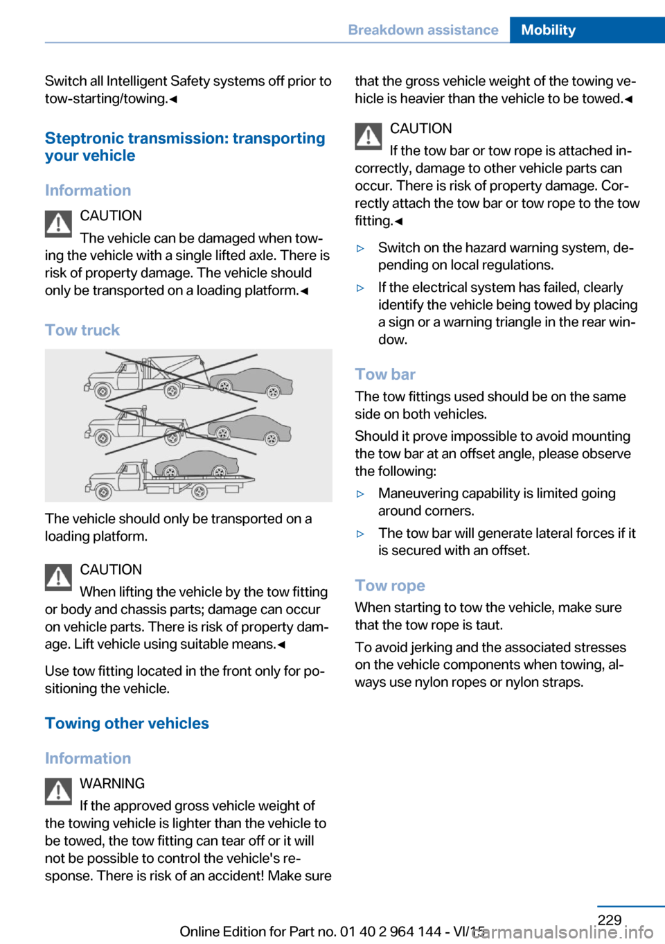
Tow truck
The vehicle should only be transported on a
loading platform.
CAUTION
When lifting the vehicle by the tow fitting
or body and chassis parts; damage can occur
on vehicle parts. There is risk of property dam‐
age. Lift vehicle using suitable means.◀
Use tow fitting located in the front only for po‐
sitioning the vehicle.
Towing other vehicles
Information WARNING
If the approved gross vehicle weight of
the towing vehicle is lighter than the vehicle to be towed, the tow fitting can tear off or it will
not be possible to control the vehicle's re‐
sponse. There is risk of an accident! Make sure
that the gross vehicle weight of the towing ve‐
hicle is heavier than the vehicle to be towed.◀
CAUTION
If the tow bar or tow rope is attached in‐
correctly, damage to other vehicle parts can
occur. There is risk of property damage. Cor‐
rectly attach the tow bar or tow rope to the tow
fitting.◀▷Switch on the hazard warning system, de‐
pending on local regulations.▷If the electrical system has failed, clearly
identify the vehicle being towed by placing
a sign or a warning triangle in the rear win‐
dow.
Tow bar
The tow fittings used should be on the same
side on both vehicles.
Should it prove impossible to avoid mounting
the tow bar at an offset angle, please observe
the following:
▷Maneuvering capability is limited going
around corners.▷The tow bar will generate lateral forces if it
is secured with an offset.
Tow rope
When starting to tow the vehicle, make sure
that the tow rope is taut.
To avoid jerking and the associated stresses
on the vehicle components when towing, al‐
ways use nylon ropes or nylon straps.
Seite 229Breakdown assistanceMobility229
Online Edition for Part no. 01 40 2 964 144 - VI/15
Page 230 of 253
Tow fitting
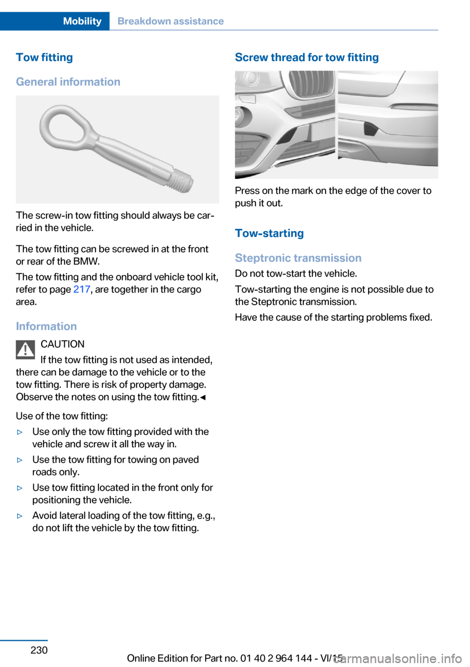
General information
The screw-in tow fitting should always be car‐
ried in the vehicle.
The tow fitting can be screwed in at the front
or rear of the BMW.
The tow fitting and the onboard vehicle tool kit,
refer to page 217, are together in the cargo
area.
Information CAUTION
If the tow fitting is not used as intended,
there can be damage to the vehicle or to the
tow fitting. There is risk of property damage.
Observe the notes on using the tow fitting.◀
Use of the tow fitting:
▷Use only the tow fitting provided with the
vehicle and screw it all the way in.▷Use the tow fitting for towing on paved
roads only.▷Use tow fitting located in the front only for
positioning the vehicle.▷Avoid lateral loading of the tow fitting, e.g.,
do not lift the vehicle by the tow fitting.Screw thread for tow fitting
Press on the mark on the edge of the cover to
push it out.
Tow-starting
Steptronic transmission
Do not tow-start the vehicle.
Tow-starting the engine is not possible due to
the Steptronic transmission.
Have the cause of the starting problems fixed.
Seite 230MobilityBreakdown assistance230
Online Edition for Part no. 01 40 2 964 144 - VI/15
Page 239 of 253

Weights
X4 xDrive28iApproved gross vehicle weightlbs/kg5,060/2,295Loadlbs/kg910/413Approved front axle loadlbs/kg2,370/1,075Approved rear axle loadlbs/kg2,820/1,279Approved roof load capacitylbs/kg220/100Cargo area capacitycu ft17.7–49.4Canada: trunk capacityliters500–1,400
X4 xDrive35iApproved gross vehicle weightlbs/kg5,180/2,350Loadlbs/kg910/413Approved front axle loadlbs/kg2,490/1,129Approved rear axle loadlbs/kg2,820/1,279Approved roof load capacitylbs/kg220/100Cargo area capacitycu ft17.7–49.4Canada: trunk capacityliters500–1,400
Capacities
US gal/litersNotesFuel tank, approx.17.7/67Fuel quality, refer to
page 194Seite 239Technical dataReference239
Online Edition for Part no. 01 40 2 964 144 - VI/15
Page 243 of 253
BMW maintenance sys‐tem 215
Bonus range, ECO PRO 185
Bottle holder, see Cu‐ pholder 171
Brake assistant 126
Brake discs, break-in 176
Brake force display 125
Brake lights, adaptive 125
Brake lights, brake force dis‐ play 125
Brake pads, break-in 176
Braking, hints 178
Breakdown assistance 226
Break-in 176
Brightness of Control Dis‐ play 95
Bulb replacement 217
Bulb replacement, front 218
Bulb replacement, rear 221
Bulbs and lights 217
Button, RES 136
Button, Start/Stop 67
Bypassing, see Jump-start‐ ing 227
C
California Proposition 65 Warning 8
Camera lenses, care 234
Camera, rearview cam‐ era 145
Camera, Side View 149
Camera, Top View 148
Can holder, see Cu‐ pholder 171
Car battery 224
Car care products 232
Care, displays 234
Care, vehicle 232
Cargo 180
Cargo area 168
Cargo area, enlarging 168
Cargo area, storage compart‐ ments 172 Cargo cover 168
Cargo, securing 181
Cargo straps, securing cargo 181
Car key, see Remote con‐ trol 34
Carpet, care 234
Car wash 231
Catalytic converter, see Hot exhaust system 177
CBS Condition Based Serv‐ ice 215
CD/Multimedia, see user's manual for Navigation, En‐
tertainment and Communi‐
cation
Center armrest 171
Center console 16
Central locking system 40
Central screen, see Control Display 18
Changes, technical, see Own Safety 7
Changing parts 217
Changing wheels 223
Changing wheels/tires 201
Chassis number, see vehicle identification number 10
Check Control 83
Checking the oil level elec‐ tronically 209
Children, seating position 63
Children, transporting safely 63
Child restraint fixing sys‐ tem 63
Child restraint fixing system LATCH 65
Child restraint fixing systems, mounting 64
Child safety locks 66
Child seat, mounting 64
Child seats 63
Chrome parts, care 233
Cigarette lighter 165
Cleaning displays 234 Climate control 155, 158
Clock 87
Closing/opening via door lock 39
Closing/opening with remote control 37
Closing the tailgate with no- touch activation 44
Clothes hooks 172
Coasting 187
Coasting with engine decou‐ pled, coasting 187
Coasting with idling en‐ gine 187
Cockpit 14
Combination switch, see Turn signals 73
Combination switch, see Wiper system 74
Comfort Access 42
COMFORT program, Dy‐ namic Driving Control 131
Compartments in the doors 171
Compass 93
Compressor 203
Condensation on win‐ dows 157, 160
Condensation under the vehi‐ cle 179
Condition Based Service CBS 215
Confirmation signal 45
ConnectedDrive, see user's manual for Navigation, En‐
tertainment and Communi‐
cation
ConnectedDrive Services
Connecting electrical devi‐ ces 166
Continued driving with a flat tire 108 , 111
Control Display 18
Control Display, settings 94
Controller 19 Seite 243Everything from A to ZReference243
Online Edition for Part no. 01 40 2 964 144 - VI/15
Page 244 of 253

Control systems, driving sta‐bility 126
Convenient opening with the remote control 38
Coolant 213
Coolant temperature 87
Cooling function 156, 159
Cooling, maximum 159
Cooling system 213
Cornering light 100
Corrosion on brake discs 178
Cosmetic mirror 165
Courtesy lamps during un‐ locking 37
Courtesy lamps with the vehi‐ cle locked 38
Cruise control 139
Cruise control, active with Stop & Go 133
Cruising range 88
Cupholder 171
Current fuel consumption 88
D
Damage, tires 201
Damping control, dy‐ namic 129
Data, technical 238
Date 88
Daytime running lights 100
Daytime running lights, bulb replacement 219
Defrosting, see Windows, de‐ frosting 157, 160
Dehumidifying, air 156, 159
Deleting personal data 25
Deletion of personal data 25
Destination distance 93
Digital clock 87
Dimensions 238
Dimmable exterior mirrors 61
Dimmable interior rearview mirror 61
Direction indicator, see Turn signals 73 Display, electronic, instru‐
ment cluster 82
Display in windshield 95
Display lighting, see Instru‐ ment lighting 102
Displays, cleaning 234
Disposal, coolant 214
Disposal, vehicle battery 225
Distance control, see PDC 142
Distance to destination 93
Divided screen view, split screen 23
Door lock 39
Door lock, see Remote con‐ trol 34
Downhill control 128
Drive-off assistant 132
Drive-off assistant, see DSC 126
Driving Dynamics Con‐ trol 130
Driving instructions, break- in 176
Driving mode 130
Driving notes, general 177
Driving on bad roads 176
Driving stability control sys‐ tems 126
Driving tips 177
DSC Dynamic Stability Con‐ trol 126
DTC Dynamic Traction Con‐ trol 127
Dynamic Damping Con‐ trol 129
Dynamic Stability Control DSC 126
Dynamic Traction Control DTC 127
E ECO PRO 184
ECO PRO, bonus range 185
ECO PRO display 184 ECO PRO driving mode 184
ECO PRO mode 184
ECO PRO Tip - driving in‐ struction 186
EfficientDynamics 186
Electronic displays, instru‐ ment cluster 82
Electronic oil measure‐ ment 209
Electronic Stability Program ESP, see DSC 126
Emergency detection, remote control 35
Emergency release, fuel filler flap 192
Emergency Request 226
Emergency start function, en‐ gine start 35
Emergency unlocking, tail‐ gate 42
Emergency unlocking, trans‐ mission lock 80
Energy Control 88
Energy recovery 88
Engine, automatic Start/Stop function 69
Engine, automatic switch- off 69
Engine compartment 207
Engine compartment, work‐ ing in 207
Engine coolant 213
Engine idling when driving, coasting 187
Engine oil 209
Engine oil, adding 210
Engine oil additives 211
Engine oil change 211
Engine oil filler neck 210
Engine oil temperature 87
Engine oil types, alterna‐ tive 211
Engine oil types, suitable 211
Engine start during malfunc‐ tion 35 Seite 244ReferenceEverything from A to Z244
Online Edition for Part no. 01 40 2 964 144 - VI/15