2015 BMW I8 ad blue
[x] Cancel search: ad bluePage 38 of 224
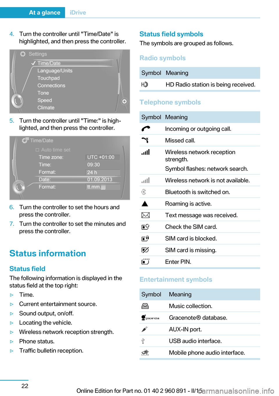
4.Turn the controller until "Time/Date" is
highlighted, and then press the controller.5.Turn the controller until "Time:" is high‐
lighted, and then press the controller.6.Turn the controller to set the hours and
press the controller.7.Turn the controller to set the minutes and
press the controller.
Status information
Status field The following information is displayed in the
status field at the top right:
▷Time.▷Current entertainment source.▷Sound output, on/off.▷Locating the vehicle.▷Wireless network reception strength.▷Phone status.▷Traffic bulletin reception.Status field symbols
The symbols are grouped as follows.
Radio symbolsSymbolMeaning HD Radio station is being received.
Telephone symbols
SymbolMeaning Incoming or outgoing call. Missed call. Wireless network reception
strength.
Symbol flashes: network search. Wireless network is not available. Bluetooth is switched on. Roaming is active. Text message was received. Check the SIM card. SIM card is blocked. SIM card is missing. Enter PIN.
Entertainment symbols
SymbolMeaning Music collection. Gracenote® database. AUX-IN port. USB audio interface. Mobile phone audio interface.Seite 22At a glanceiDrive22
Online Edition for Part no. 01 40 2 960 891 - II/15
Page 79 of 224
Lighting lights up steady blue
After drive readiness is switched on, light turns
blue. The vehicle is ready to drive. The READY
indicator lights up in the instrument cluster. In
addition, a signal sounds.
Lighting off
Drive readiness, operating readiness and
radio-ready state are turned off. The vehicle is
in the idle state. The charging cable may be
connected.
Activating drive readiness1.Close the driver's door.2.Depress the brake pedal.3.Press the Start/Stop button.
Drive readiness is active, electric driving, Silent
Start or Start of the combustion engine.
Electric drive readiness, Silent Start
The vehicle is ready for driving without starting
the combustion engine.
Silent Start is possible if the requirements for
Electric driving, refer to page 64, are met.
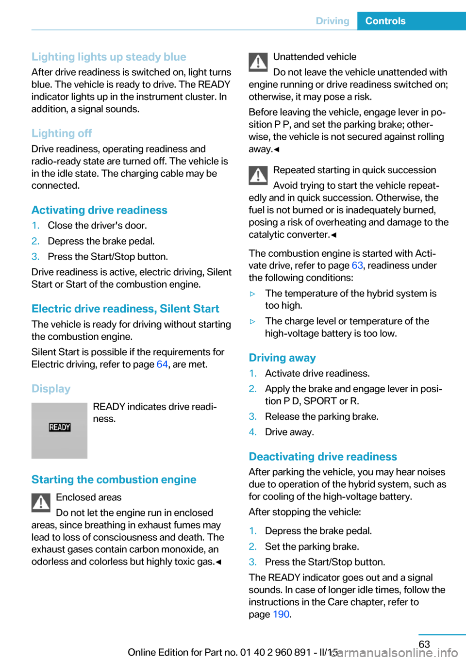
Display READY indicates drive readi‐
ness.
Starting the combustion engine Enclosed areas
Do not let the engine run in enclosed
areas, since breathing in exhaust fumes may
lead to loss of consciousness and death. The
exhaust gases contain carbon monoxide, an
odorless and colorless but highly toxic gas.◀
Unattended vehicle
Do not leave the vehicle unattended with
engine running or drive readiness switched on;
otherwise, it may pose a risk.
Before leaving the vehicle, engage lever in po‐
sition P P, and set the parking brake; other‐
wise, the vehicle is not secured against rolling
away.◀
Repeated starting in quick succession
Avoid trying to start the vehicle repeat‐
edly and in quick succession. Otherwise, the
fuel is not burned or is inadequately burned,
posing a risk of overheating and damage to the
catalytic converter.◀
The combustion engine is started with Acti‐
vate drive, refer to page 63, readiness under
the following conditions:▷The temperature of the hybrid system is
too high.▷The charge level or temperature of the
high-voltage battery is too low.
Driving away
1.Activate drive readiness.2.Apply the brake and engage lever in posi‐
tion P D, SPORT or R.3.Release the parking brake.4.Drive away.
Deactivating drive readiness
After parking the vehicle, you may hear noises due to operation of the hybrid system, such as
for cooling of the high-voltage battery.
After stopping the vehicle:
1.Depress the brake pedal.2.Set the parking brake.3.Press the Start/Stop button.
The READY indicator goes out and a signal
sounds. In case of longer idle times, follow the
instructions in the Care chapter, refer to
page 190.
Seite 63DrivingControls63
Online Edition for Part no. 01 40 2 960 891 - II/15
Page 92 of 224
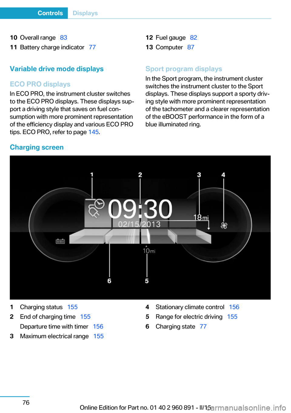
10Overall range 8311Battery charge indicator 7712Fuel gauge 8213Computer 87Variable drive mode displays
ECO PRO displays In ECO PRO, the instrument cluster switches
to the ECO PRO displays. These displays sup‐
port a driving style that saves on fuel con‐
sumption with more prominent representation
of the efficiency display and various ECO PRO
tips. ECO PRO, refer to page 145.Sport program displays
In the Sport program, the instrument cluster
switches the instrument cluster to the Sport
displays. These displays support a sporty driv‐
ing style with more prominent representation
of the tachometer and a clearer representation
of the eBOOST performance in the form of a
blue illuminated ring.
Charging screen
1Charging status 1552End of charging time 155
Departure time with timer 1563Maximum electrical range 1554Stationary climate control 1565Range for electric driving 1556Charging state 77Seite 76ControlsDisplays76
Online Edition for Part no. 01 40 2 960 891 - II/15
Page 93 of 224
Displays of the hybrid
system
Displays in the instrument cluster
The concept The following functions of the hybrid system
are displayed:▷High-voltage battery charge indicator, refer
to page 77.▷Max eDrive, refer to page 64▷Maintaining charging state, refer to
page 78.▷Electric driving: ePOWER, refer to
page 77.▷Acceleration boost: eBOOST, refer to
page 78.▷Energy recovery: CHARGE, refer to
page 78.▷Drive readiness: READY, refer to
page 77.
The display depends on the system's operat‐
ing condition.
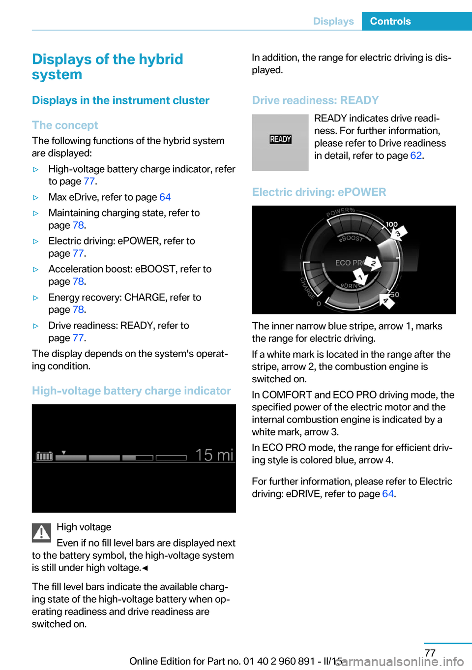
High-voltage battery charge indicator
High voltage
Even if no fill level bars are displayed next
to the battery symbol, the high-voltage system
is still under high voltage.◀
The fill level bars indicate the available charg‐
ing state of the high-voltage battery when op‐
erating readiness and drive readiness are
switched on.
In addition, the range for electric driving is dis‐
played.
Drive readiness: READY READY indicates drive readi‐
ness. For further information,
please refer to Drive readiness
in detail, refer to page 62.
Electric driving: ePOWER
The inner narrow blue stripe, arrow 1, marks
the range for electric driving.
If a white mark is located in the range after the
stripe, arrow 2, the combustion engine is
switched on.
In COMFORT and ECO PRO driving mode, the
specified power of the electric motor and the
internal combustion engine is indicated by a
white mark, arrow 3.
In ECO PRO mode, the range for efficient driv‐
ing style is colored blue, arrow 4.
For further information, please refer to Electric
driving: eDRIVE, refer to page 64.
Seite 77DisplaysControls77
Online Edition for Part no. 01 40 2 960 891 - II/15
Page 94 of 224
Energy recovery: CHARGE
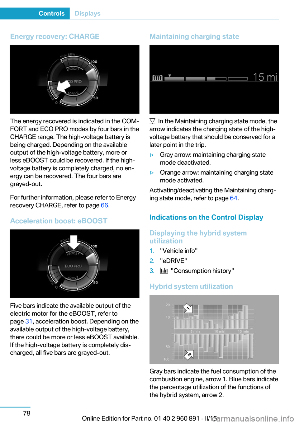
The energy recovered is indicated in the COM‐
FORT and ECO PRO modes by four bars in the
CHARGE range. The high-voltage battery is
being charged. Depending on the available
output of the high-voltage battery, more or
less eBOOST could be recovered. If the high-
voltage battery is completely charged, no en‐
ergy can be recovered. The four bars are
grayed-out.
For further information, please refer to Energy
recovery CHARGE, refer to page 66.
Acceleration boost: eBOOST
Five bars indicate the available output of the
electric motor for the eBOOST, refer to
page 31, acceleration boost. Depending on the
available output of the high-voltage battery,
there could be more or less eBOOST available.
If the high-voltage battery is completely dis‐
charged, all five bars are grayed-out.
Maintaining charging state
In the Maintaining charging state mode, the
arrow indicates the charging state of the high-
voltage battery that should be conserved for a
later point in the trip.
▷Gray arrow: maintaining charging state
mode deactivated.▷Orange arrow: maintaining charging state
mode activated.
Activating/deactivating the Maintaining charg‐
ing state mode, refer to page 64.
Indications on the Control Display
Displaying the hybrid system
utilization
1."Vehicle info"2."eDRIVE"3. "Consumption history"
Hybrid system utilization
Gray bars indicate the fuel consumption of the
combustion engine, arrow 1. Blue bars indicate
the percentage utilization of the functions of
the hybrid system, arrow 2.
Seite 78ControlsDisplays78
Online Edition for Part no. 01 40 2 960 891 - II/15
Page 95 of 224

One bar indicates one minute.
The combustion engine's average fuel con‐
sumption is indicated by a line above the bar
display and as a value to the right of the graph.
Displaying the energy flow1."Vehicle info"2."eDRIVE"3. "Energy flow"
Energy flow of the hybrid system
The following are displayed:
▷Active components of the hybrid system.▷Direction of the energy flows:
Orange: energy flow of the combustion en‐
gine.
Blue: energy flow of the hybrid system▷Driving states:▷ePOWER.▷POWER.▷eBOOST.▷CHARGE.▷Coasting.▷Charging.▷System requirements of the hybrid system,
e. g., drive system not yet warmed up to
operating temperature.▷Driving requirement, e. g., transmission se‐
lector lever in the Sport position.Adapting to the course of the road
When the navigation system destination guid‐
ance is active, hybrid operation adapts to spe‐
cific route sections.
Use of the hybrid system is optional.
Symbols in the energy flow display indicate
that a situation has been detected ahead and
hybrid operation is prepared for it.
SymbolsSymbolMeaningDownhill gradients: the system is
ready to charge the high-voltage
battery.Target zone: ePOWER electric driv‐
ing is being prepared.
Check Control
The concept The Check Control system monitors functions
in the vehicle and notifies you of malfunctions
in the monitored systems.
A Check Control message is displayed as a
combination of indicator or warning lights and
text messages in the instrument cluster and in
the Head-up Display.
In addition, an acoustic signal may sound and a text message may appear on the Control Dis‐
play.
Indicator/warning lights
General information
The indicator and warning lights in the instru‐
ment cluster can light up in a variety of combi‐
nations and colors.
Several lights indicate function checks and
light up only temporarily when drive readiness
or operating readiness are activated.
Seite 79DisplaysControls79
Online Edition for Part no. 01 40 2 960 891 - II/15
Page 97 of 224

ing the area of the interference, the system
automatically becomes active again.▷TPM could not conclude the reset: perform
the reset of the system again.▷A wheel without TPM electronics is fitted:
have the service center check it if needed.▷Malfunction: have the system checked by
your service center.
For more information, see Tire Pressure Moni‐
tor, refer to page 99.
Steering system Steering system in some cases defec‐
tive.
Have the steering system checked by
the service center.
Engine functions Have the vehicle checked by the serv‐ice center.
For additional information, refer to On-
board Diagnostics socket, refer to page 179.
Acoustic pedestrian protection inactive Acoustic pedestrian protection possi‐
bly defective.
Have the system checked by the serv‐
ice center.
Green lights Turn signal Turn signal on.
Unusually rapid flashing of the indicator
lamp indicates that a turn signal bulb
has failed.
For additional information, refer to Turn signal, refer to page 67.
Parking lights, headlight control
Parking lights or headlights are acti‐
vated.
For additional information, refer to
Parking lights/low beams, headlight control, re‐
fer to page 92.
High-beam Assistant High-beam Assistant is switched on.
High beams are activated and off auto‐
matically as a function of the traffic sit‐
uation.
For additional information, refer to High-beam
Assistant, refer to page 94.
Cruise control The system is switched on. It maintains
the speed that was set using the con‐
trol elements on the steering wheel.
Blue lights
High beams High beams are activated.
For additional information, refer to High
beams, refer to page 68.
General lamps
Check Control At least one Check Control message is
displayed or is stored. The symbol is
shown in the display of the instrument
cluster.
Text messagesText messages in combination with a symbol
in the instrument cluster explain a Check Con‐ trol message and the meaning of the indicator
and warning lights.Seite 81DisplaysControls81
Online Edition for Part no. 01 40 2 960 891 - II/15
Page 109 of 224

Setting the durationOn the Control Display:1."Settings"2."Lighting"3."Pathway lighting:"4.Set length of time.
Settings are stored for the profile currently in
use.
Automatic headlight control
Position of switch
: the low beams are acti‐
vated and off automatically, e.g., in tunnels, in
twilight or if there is precipitation. The indicator
lamp in the instrument cluster lights up.
When emerging from a tunnel during the day,
the low beams are not switched off immedi‐
ately but instead only after approx. 2 minutes.
A blue sky with the sun low on the horizon can
cause the lights to be switched on.
Personal responsibility
The automatic headlight control cannot
serve as a substitute for your personal judg‐
ment in determining when to turn the lights on
in response to ambient lighting conditions.
E. g. the sensors are unable to detect fog or
hazy weather. To avoid safety risks under
these conditions, you should always switch on
the lights manually.◀
Daytime running lights With the ignition switched on, the daytime run‐
ning lights light up in position
, or
. After operating readiness is switched off,
the parking lights light up in position
.
Activating/deactivating In some countries, daytime running lights are
mandatory, so it may not be possible to deacti‐
vate the daytime running lights.
On the Control Display:
1."Settings"2."Lighting"3."Daytime running lamps"
Settings are stored for the profile currently in
use.
Roadside parking lights
The vehicle can be illuminated on one side.
Switching on With operating readiness switched off, press
the lever either up or down past the resistance
point for approx. 2 seconds.
Switch off Briefly press the lever to the resistance point in
the opposite direction.
Variable light distribution The concept This variable light distribution ensures that the
roadway is still more effectively illuminated,
depending on the vehicle speed.
The light distribution is automatically adjusted
to the speed. The freeway lights are activated
at speeds above 110 km/h after approx.
30 seconds or at a speed of 140 km/h.
Activating Position of switch
with the ignition
switched on.
Seite 93LightsControls93
Online Edition for Part no. 01 40 2 960 891 - II/15