2015 BMW 740LI XDRIVE SEDAN window
[x] Cancel search: windowPage 71 of 314
ClosingWARNING
When operating the windows, body parts
and objects can be jammed. There is risk of in‐
juries or risk of property damage. Make sure
that the area of movement of the windows is
clear during opening and closing.◀▷Pull the switch to the resistance
point.
The window closes while the switch is
held.▷Pull the switch beyond the resistance
point.
The window closes automatically. Pulling
again stops the motion.
See also: closing by means of Comfort Access,
refer to page 65.
Pinch protection system WARNING
When operating the windows, body parts
and objects can be jammed. There is risk of in‐
juries or risk of property damage. Make sure
that the area of movement of the windows is
clear during opening and closing.◀
WARNING
Accessories on the windows such as an‐
tennas can impact jam protection. There is risk
of injuries. Do not install accessories in the
area of movement of the windows.◀
If closing force exceeds a specific margin as a
window closes, closing is interrupted.
The window reopens slightly.
Closing without the pinch protection system
WARNING
When operating the windows, body parts
and objects can be jammed. There is risk of in‐
juries or risk of property damage. Make sure
that the area of movement of the windows is
clear during opening and closing.◀
In case of danger from the outside or if ice
might prevent normal closing, proceed as fol‐
lows:1.Pull the switch past the resistance point
and hold it there.
The pinch protection is limited and the
window reopens slightly if the closing force
exceeds a certain margin.2.Pull the switch past the resistance point
again within approx. 4 seconds and hold it
there.
The window closes without jam protection.
Safety switch
The concept With the safety switch for the rear, it is possible
to block particular functions. This makes sense, for example, if children or animals are
carried in the rear.
General information
The following functions can be locked using
the switch:
▷Opening and closing of the rear windows
using the switches in the rear.▷Operation of the roller sunblind in the rear
window using the switches in the rear.▷Operation of the roller sunblinds in the side
windows using the switches in the rear.▷Adjustment of the power rear seats.▷Operation of the rear sliding visor using the
switches in the rear.
Information
WARNING
When operating the windows, body parts
and objects can be jammed. There is risk of in‐
juries or risk of property damage. Make sure
Seite 71Opening and closingControls71
Online Edition for Part no. 0140 2 964 330 - VI/15
Page 72 of 314
that the area of movement of the windows is
clear during opening and closing.◀
In order to prevent uncontrolled closing of the
windows, press the safety switch, e.g. if chil‐
dren or animals are carried in the rear.
Switching on and off Press button.
The LED lights up if the safety func‐
tion is switched on.
Roller sunblinds
General information The safety switch, refer to page 71, in the driv‐
er's door can be used to prevent children, e.g.,
from operating the roller sunblinds using the
switches in the rear.
BMW Touch Command The roller sunblinds can also be operated us‐
ing BMW Touch Command.
Information If you are no longer able to move the roller sun‐
blinds after having activated them consecu‐
tively a number of times, the system is blocked
for a limited time to prevent overheating. Let
the system cool.
The roller sunblinds cannot be moved at low
interior temperatures.Roller sunblind in the rear window
Overview
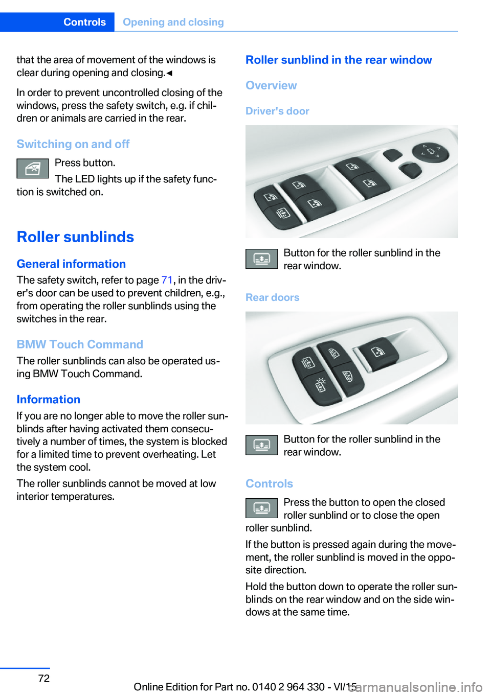
Driver's door
Button for the roller sunblind in the
rear window.
Rear doors
Button for the roller sunblind in the
rear window.
Controls Press the button to open the closed
roller sunblind or to close the open
roller sunblind.
If the button is pressed again during the move‐
ment, the roller sunblind is moved in the oppo‐
site direction.
Hold the button down to operate the roller sun‐
blinds on the rear window and on the side win‐
dows at the same time.
Seite 72ControlsOpening and closing72
Online Edition for Part no. 0140 2 964 330 - VI/15
Page 73 of 314
Roller sunblinds in the side windows
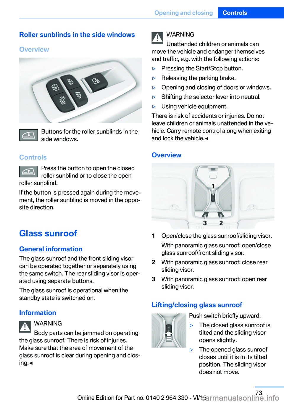
Overview
Buttons for the roller sunblinds in the
side windows.
Controls Press the button to open the closed
roller sunblind or to close the open
roller sunblind.
If the button is pressed again during the move‐
ment, the roller sunblind is moved in the oppo‐
site direction.
Glass sunroof General information
The glass sunroof and the front sliding visor
can be operated together or separately using
the same switch. The rear sliding visor is oper‐
ated using separate buttons.
The glass sunroof is operational when the
standby state is switched on.
Information WARNING
Body parts can be jammed on operating
the glass sunroof. There is risk of injuries.
Make sure that the area of movement of the
glass sunroof is clear during opening and clos‐
ing.◀
WARNING
Unattended children or animals can
move the vehicle and endanger themselves
and traffic, e.g. with the following actions:▷Pressing the Start/Stop button.▷Releasing the parking brake.▷Opening and closing of doors or windows.▷Shifting the selector lever into neutral.▷Using vehicle equipment.
There is risk of accidents or injuries. Do not
leave children or animals unattended in the ve‐
hicle. Carry remote control along when exiting
and lock the vehicle.◀
Overview
1Open/close the glass sunroof/sliding visor.
With panoramic glass sunroof: open/close
glass sunroof/front sliding visor.2With panoramic glass sunroof: close rear
sliding visor.3With panoramic glass sunroof: open rear
sliding visor.
Lifting/closing glass sunroof
Push switch briefly upward.
▷The closed glass sunroof is
tilted and the sliding visor
opens slightly.▷The opened glass sunroof
closes until it is in its tilted
position. The sliding visor
does not move.Seite 73Opening and closingControls73
Online Edition for Part no. 0140 2 964 330 - VI/15
Page 84 of 314
Adjusting the height
Manual head restraints
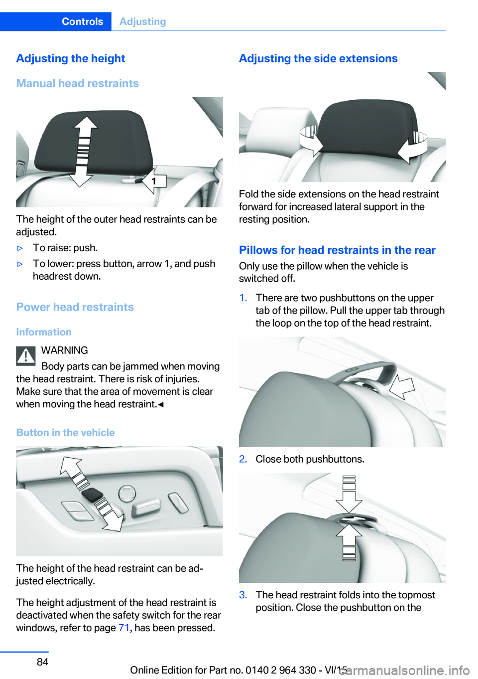
The height of the outer head restraints can be
adjusted.
▷To raise: push.▷To lower: press button, arrow 1, and push
headrest down.
Power head restraints
Information WARNING
Body parts can be jammed when moving
the head restraint. There is risk of injuries.
Make sure that the area of movement is clear
when moving the head restraint.◀
Button in the vehicle
The height of the head restraint can be ad‐
justed electrically.
The height adjustment of the head restraint is
deactivated when the safety switch for the rear
windows, refer to page 71, has been pressed.
Adjusting the side extensions
Fold the side extensions on the head restraint
forward for increased lateral support in the
resting position.
Pillows for head restraints in the rear
Only use the pillow when the vehicle is
switched off.
1.There are two pushbuttons on the upper
tab of the pillow. Pull the upper tab through
the loop on the top of the head restraint.2.Close both pushbuttons.3.The head restraint folds into the topmost
position. Close the pushbutton on theSeite 84ControlsAdjusting84
Online Edition for Part no. 0140 2 964 330 - VI/15
Page 93 of 314
Transporting children safelyVehicle features and optionsThis chapter describes all standard, country-
specific and optional features offered with the
series. It also describes features that are not
necessarily available in your car, e. g., due tothe selected options or country versions. This
also applies to safety-related functions and
systems. The respectively applicable country
provisions must be observed when using the
respective features and systems.
The right place for children
Information
WARNING
Unattended children or animals can
move the vehicle and endanger themselves
and traffic, e.g. with the following actions:▷Pressing the Start/Stop button.▷Releasing the parking brake.▷Opening and closing of doors or windows.▷Shifting the selector lever into neutral.▷Using vehicle equipment.
There is risk of accidents or injuries. Do not
leave children or animals unattended in the ve‐
hicle. Carry remote control along when exiting
and lock the vehicle.◀
Children should always be in the rear WARNING
Persons shorter than 5 ft, 150 cm cannot
correctly fasten the safety belt without suitable
additional restraint systems. The protective ef‐
fect of the safety belts can be limited or lost
when safety belts are fastened incorrectly. An
incorrectly fastened safety belt can cause ad‐
ditional injuries, e.g. in the event of an accident
or during braking and evasive maneuvers.
There is risk of injuries or danger to life. Secure
persons shorter than 5 ft, 150 cm using suita‐
ble restraint systems.◀
Accident research shows that the safest place
for children is in the back seat.
Only transport children younger than 13 years
of age or shorter than 5 ft, 150 cm in the rear in
child restraint systems provided in accordance
with the age, weight and size of the child.
Children 13 years of age or older must wear a
safety belt as soon as a suitable child restraint
system can no longer be used due to their age,
weight and size.
Children on the front passenger seat
Before using a child restraint system on the
front passenger seat, ensure that the front,
knee, and side airbags on the front passenger
side are deactivated. Automatic deactivation of
front-seat passenger airbags, refer to
page 138.
Information WARNING
Active front-seat passenger airbags can
injure a child in a child restraint system when
the airbags are activated. There is risk of inju‐
ries. Make sure that the front-seat passenger
airbags are deactivated and that the PASSEN‐
GER AIRBAG OFF indicator lamp lights up.◀Seite 93Transporting children safelyControls93
Online Edition for Part no. 0140 2 964 330 - VI/15
Page 95 of 314
LATCH child restraint systemLATCH: Lower Anchors and Tether for Chil‐
dren.
Information
Pay attention to the operating and safety infor‐
mation of the child restraint system manufac‐
turer when installing and using LATCH child
restraint fixing system.
Mounts for the lower LATCH anchors
General information
The lower anchors may be used to attach the
CRS to the vehicle seat up to a combined child
and CRS weight of 65 lb/30 kg when the child
is restrained by the internal harnesses.
Information WARNING
If the LATCH child restraint fixing sys‐
tems are not correctly engaged, the protective
effect of the LATCH child restraint fixing sys‐
tem can be limited. There is risk of injuries or
danger to life. Make sure that the lower an‐
chors are securely engaged and that the
LATCH child restraint fixing system fits se‐
curely against the backrest.◀
Position The corresponding symbol shows the
mounts for the lower LATCH anchors.
Seats equipped with lower anchors are
marked with a pair, 2, of LATCH sym‐
bols. It is not recommended to use the
inner lower anchors of standard outer
LATCH positions to fasten a child restraint system on the middle seat. Use the vehicle
seat belt instead for the middle seat.Before installing LATCH child
restraint systems
Pull the belt away from the area of the child re‐
straint system.
Without comfort seats in the rear:
Assembly of LATCH child restraint
systems1.Install child restraint system, see manufac‐
turer's information.2.Ensure that both LATCH anchors are prop‐
erly connected.
With comfort rear seats: Assembly of
LATCH child restraint fixing systems
1.Before mounting, adjust the seats to their
basic position, refer to page 80.2.For better accessibility, tilt the backrest
back slightly.3.Install child restraint system, see manufac‐
turer's information.4.Ensure that both LATCH anchors are prop‐
erly connected.5.After mounting, move the backrest back up
slightly so that the child restraint system
rests lightly against the backrest.
Child restraint fixing system with a
tether strap
Mounting points The respective symbol shows the an‐
chor for the upper retaining strap.
Seats with an upper Top Tether are
marked with this symbol. It can be found on
the rear seat backrest or the rear window shelf.
Seite 95Transporting children safelyControls95
Online Edition for Part no. 0140 2 964 330 - VI/15
Page 96 of 314
InformationCAUTION
The mounting points for the upper re‐
taining straps of child restraint systems are
only provided for these retaining straps. When
other objects are mounted, the anchors can be
damaged. There is risk of property damage.
Only mount child restraint systems to the up‐
per retaining straps.◀
Retaining strap guide WARNING
If the upper retaining strap is incorrectly
used for the child restraint system, the protec‐
tive effect can be reduced. There is risk of inju‐
ries. Make sure that the upper retaining strap is
not guided across sharp edges and without
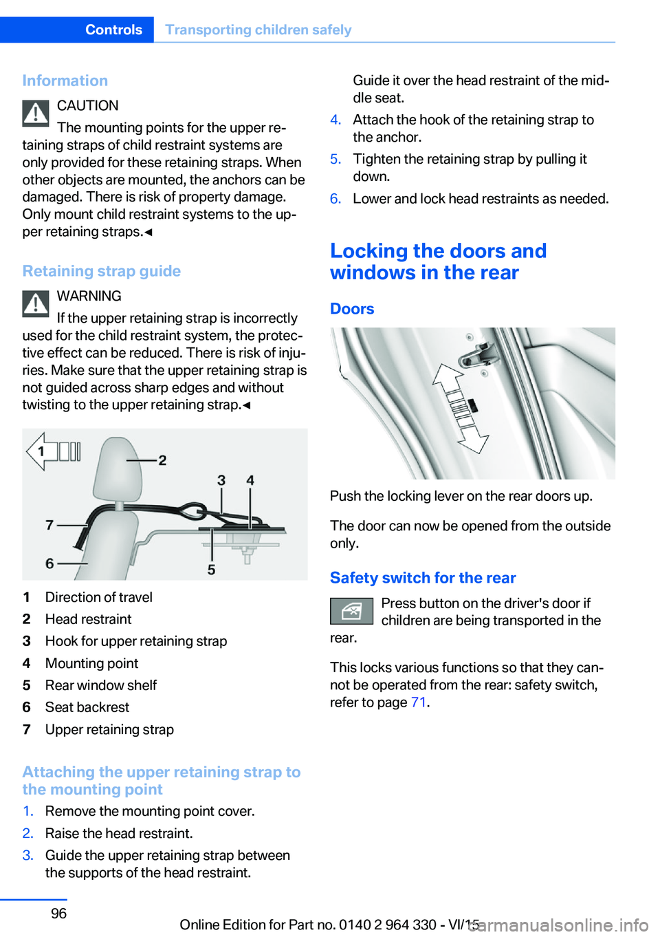
twisting to the upper retaining strap.◀1Direction of travel2Head restraint3Hook for upper retaining strap4Mounting point5Rear window shelf6Seat backrest7Upper retaining strap
Attaching the upper retaining strap to
the mounting point
1.Remove the mounting point cover.2.Raise the head restraint.3.Guide the upper retaining strap between
the supports of the head restraint.Guide it over the head restraint of the mid‐
dle seat.4.Attach the hook of the retaining strap to
the anchor.5.Tighten the retaining strap by pulling it
down.6.Lower and lock head restraints as needed.
Locking the doors and
windows in the rear
Doors
Push the locking lever on the rear doors up.
The door can now be opened from the outside
only.
Safety switch for the rear Press button on the driver's door if
children are being transported in the
rear.
This locks various functions so that they can‐
not be operated from the rear: safety switch,
refer to page 71.
Seite 96ControlsTransporting children safely96
Online Edition for Part no. 0140 2 964 330 - VI/15
Page 98 of 314
3.Set the parking brake.
Before driving into a car wash
So that the vehicle can roll into a car wash ob‐
serve instructions for going into an automatic
car wash, refer to page 291.
Auto Start/Stop function
The concept The Auto Start/Stop function helps save fuel.
The system switches off the engine during a
stop, e.g., in traffic congestion or at traffic lights. Drive readiness remains switched on.
The engine starts again automatically for driv‐
ing off.
Information After every engine start via the Start/Stop but‐
ton, the Auto Start/Stop function is activated or
deactivated, according to the last setting, refer
to page 99. If the Auto Start/Stop function is
active, it is available as soon as a speed of ap‐
prox. 3 mph, approx. 5 km/h is exceeded.
Engine stop
The engine is switched off automatically dur‐
ing a stop under the following conditions:
▷The selector lever is in selector lever posi‐
tion D.▷The brake pedal remains pressed while the
vehicle is stationary or the vehicle is held
by Automatic Hold.▷The driver's safety belt is buckled or the
driver's door is closed.
The air flow from the air conditioner is reduced
when the engine is switched off.
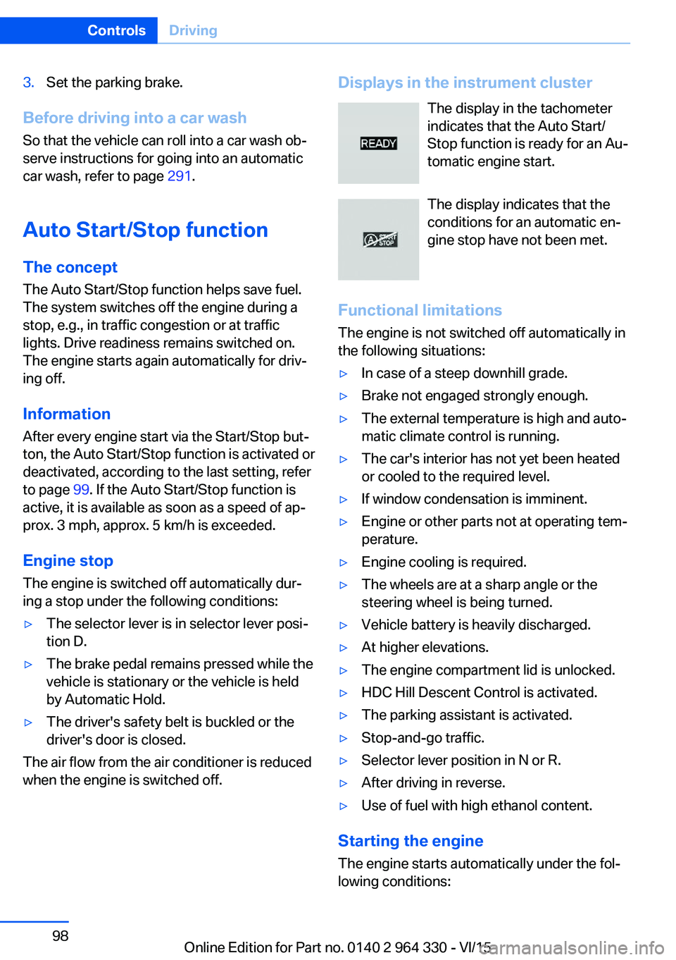
Displays in the instrument cluster
The display in the tachometer
indicates that the Auto Start/
Stop function is ready for an Au‐
tomatic engine start.
The display indicates that the
conditions for an automatic en‐
gine stop have not been met.
Functional limitations The engine is not switched off automatically in
the following situations:▷In case of a steep downhill grade.▷Brake not engaged strongly enough.▷The external temperature is high and auto‐
matic climate control is running.▷The car's interior has not yet been heated
or cooled to the required level.▷If window condensation is imminent.▷Engine or other parts not at operating tem‐
perature.▷Engine cooling is required.▷The wheels are at a sharp angle or the
steering wheel is being turned.▷Vehicle battery is heavily discharged.▷At higher elevations.▷The engine compartment lid is unlocked.▷HDC Hill Descent Control is activated.▷The parking assistant is activated.▷Stop-and-go traffic.▷Selector lever position in N or R.▷After driving in reverse.▷Use of fuel with high ethanol content.
Starting the engine
The engine starts automatically under the fol‐
lowing conditions:
Seite 98ControlsDriving98
Online Edition for Part no. 0140 2 964 330 - VI/15