2015 BMW 5 SERIES SEDAN steering
[x] Cancel search: steeringPage 163 of 277
Cameras
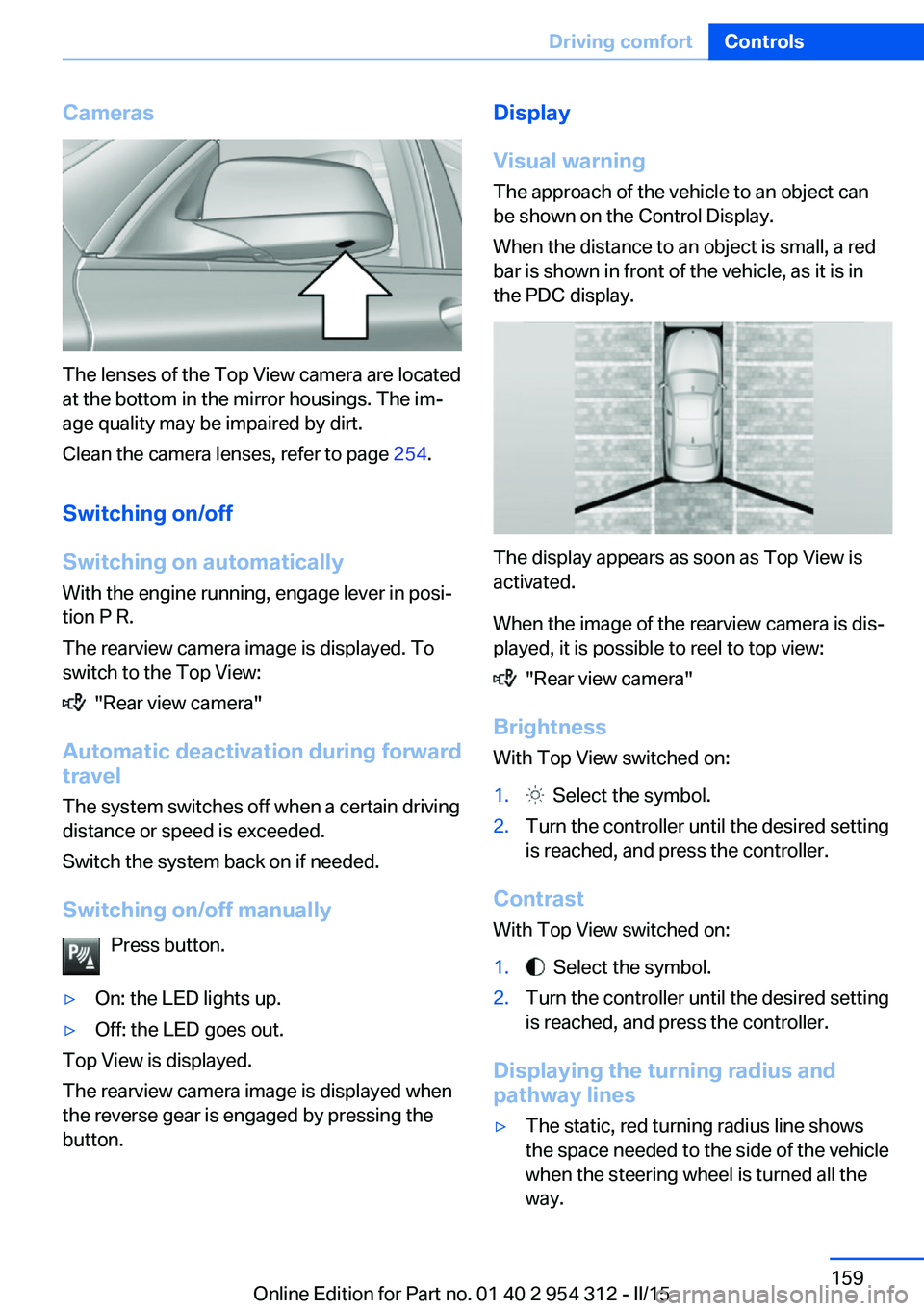
The lenses of the Top View camera are located
at the bottom in the mirror housings. The im‐
age quality may be impaired by dirt.
Clean the camera lenses, refer to page 254.
Switching on/off
Switching on automatically With the engine running, engage lever in posi‐
tion P R.
The rearview camera image is displayed. To
switch to the Top View:
"Rear view camera"
Automatic deactivation during forward
travel
The system switches off when a certain driving
distance or speed is exceeded.
Switch the system back on if needed.
Switching on/off manually Press button.
▷On: the LED lights up.▷Off: the LED goes out.
Top View is displayed.
The rearview camera image is displayed when
the reverse gear is engaged by pressing the
button.
Display
Visual warning
The approach of the vehicle to an object can
be shown on the Control Display.
When the distance to an object is small, a red
bar is shown in front of the vehicle, as it is in
the PDC display.
The display appears as soon as Top View is
activated.
When the image of the rearview camera is dis‐
played, it is possible to reel to top view:
"Rear view camera"
Brightness
With Top View switched on:
1. Select the symbol.2.Turn the controller until the desired setting
is reached, and press the controller.
Contrast
With Top View switched on:
1. Select the symbol.2.Turn the controller until the desired setting
is reached, and press the controller.
Displaying the turning radius and
pathway lines
▷The static, red turning radius line shows
the space needed to the side of the vehicle
when the steering wheel is turned all the
way.Seite 159Driving comfortControls159
Online Edition for Part no. 01 40 2 954 312 - II/15
Page 164 of 277

▷The variable, green pathway line assists
you in assessing the amount of space ac‐
tually needed to the side of the vehicle.
The lane line depends on the engaged
gear and the current steering angle. The
track line is continuously adjusted for the
steering wheel movement.
"Parking aid lines"
Turning circle and pathway lines are displayed.
System limits
Top View cannot be used in the following sit‐
uations:
▷With a door open.▷With the trunk lid open.▷With an exterior mirror folded in.▷In poor light.
A Check Control message is displayed in some
of these situations.
Parking assistant The concept
This system assists the driver in parking paral‐
lel to the road.
Ultrasound sensors measure parking spaces
on both sides of the vehicle.
Manual transmission:
The parking assistant calculates the best pos‐
sible parking line and takes control of steering
during the parking procedure.
Steptronic transmission:
The parking assistant calculates the best pos‐
sible parking line and during the parking proce‐
dure takes control of steering, the acceleration
and braking and if needed changes the gears.
Hold down the parking assistant button for the
duration of the parking procedure. At the end
of the parking procedure, the P selector lever
position is set.
When parking, also take note of the visual and
acoustic information and instructions issued
by the PDC, the parking assistant and the rear‐
view camera and react accordingly.
A component of the parking assistant is the
PDC Park Distance Control, refer to page 152.
Hints Personal responsibility
Even an active system does not relieve
the driver from personal responsibility while
driving.
Technically the system has its limits, it cannot
independently react to all traffic situations.
Monitor your driving, be on the alert, observe
the vehicle surroundings and other traffic and
react when needed - risk of accident.◀
Changes to the parking space
Changes to the parking space after it was
measured are not taken into account by the
system.
Therefore, always be alert and ready to inter‐
vene; otherwise, there is the risk of an acci‐
dent.◀
Transporting cargo
Cargo that extends beyond the perimeter
of the vehicle is not taken into account by the
system during the parking procedure.
Therefore, always be alert and ready to inter‐
vene; otherwise, there is the risk of an acci‐
dent.◀Seite 160ControlsDriving comfort160
Online Edition for Part no. 01 40 2 954 312 - II/15
Page 166 of 277
Parking assistant is activated automatically.
Switching on with the reverse gear
Shift into reverse.
The current status of the parking space search
is indicated on the Control Display.
To activate:
"Parking Assistant"
Switch off
The system can be deactivated as follows:
▷Press button.▷Switch off the ignition.
Display on the Control Display
System activated/deactivated
SymbolMeaning Gray: the system is not available.
White: the system is available but
not activated. The system is activated.
System status
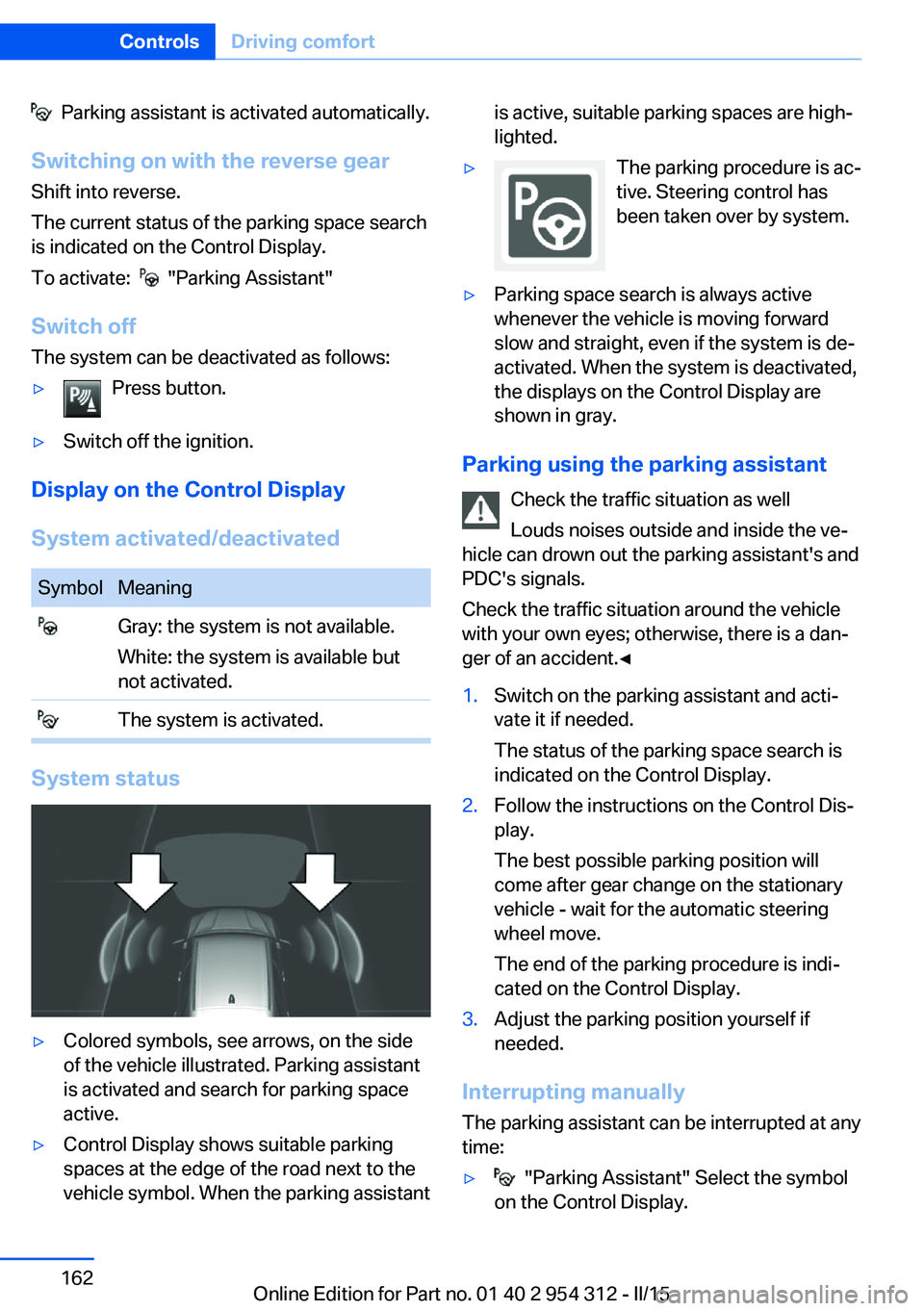
▷Colored symbols, see arrows, on the side
of the vehicle illustrated. Parking assistant
is activated and search for parking space
active.▷Control Display shows suitable parking
spaces at the edge of the road next to the
vehicle symbol. When the parking assistantis active, suitable parking spaces are high‐
lighted.▷The parking procedure is ac‐
tive. Steering control has
been taken over by system.▷Parking space search is always active
whenever the vehicle is moving forward
slow and straight, even if the system is de‐
activated. When the system is deactivated,
the displays on the Control Display are
shown in gray.
Parking using the parking assistant
Check the traffic situation as well
Louds noises outside and inside the ve‐
hicle can drown out the parking assistant's and
PDC's signals.
Check the traffic situation around the vehicle
with your own eyes; otherwise, there is a dan‐
ger of an accident.◀
1.Switch on the parking assistant and acti‐
vate it if needed.
The status of the parking space search is
indicated on the Control Display.2.Follow the instructions on the Control Dis‐
play.
The best possible parking position will
come after gear change on the stationary
vehicle - wait for the automatic steering
wheel move.
The end of the parking procedure is indi‐
cated on the Control Display.3.Adjust the parking position yourself if
needed.
Interrupting manually
The parking assistant can be interrupted at any
time:
▷ "Parking Assistant" Select the symbol
on the Control Display.Seite 162ControlsDriving comfort162
Online Edition for Part no. 01 40 2 954 312 - II/15
Page 167 of 277

▷Press button.
Interrupting automaticallyThe system is interrupted automatically in the
following situations:
▷If the driver grasps the steering wheel or if
he takes over steering.▷If a gear is selected that does not match
the instruction on the Control Display.▷If the vehicle speed exceeds approx.
6 mph/10 km/h.▷Possible on snow-covered or slippery road
surfaces.▷When there are obstacles that are hard to
overcome, such as curbs.▷When there are obstacles that suddenly
arise.▷If the Park Distance Control PDC displays
clearances that are too small.▷If a maximum number of parking attempts
or the time taken for parking is exceeded.▷If a turn signal has been actuated contrary
to the desired side for parking.▷When switching to another function on the
Control Display.
Steptronic transmission:
▷When the button is released.▷If the trunk lid is open.▷If doors are open.▷When setting the parking brake.▷During acceleration.▷When braking.▷When unfastening the driver's safety belt.
A Check Control message is displayed.
Resume An interrupted parking procedure can be con‐
tinued if needed.
Follow the instructions on the Control Display
to do this.
System limits
No parking assistance
The parking assistant does not offer assis‐
tance in the following situations:▷In tight curves.
Functional limitations
The system may not be fully functional in the
following situations:
▷On bumpy road surfaces such as gravel
roads.▷On slippery ground.▷On steep uphill or downhill grades.▷With accumulations of leaves/snow in the
parking space.
Limits of ultrasonic measurement
Ultrasonic measuring might not function under
the following circumstances:
▷For small children and animals.▷For persons with certain clothing, e.g.
coats.▷With external interference of the ultra‐
sound, e.g. from passing vehicles or loud
machines.▷When sensors are dirty, iced over, dam‐
aged or out of position.▷Under certain weather conditions such as
high relative humidity, rain, snowfall, ex‐
treme heat or strong wind.▷With tow bars and trailer couplings of other
vehicles.▷With thin or wedge-shaped objects.▷With moving objects.▷With elevated, protruding objects such as
ledges or cargo.▷With objects with corners and sharp edges.Seite 163Driving comfortControls163
Online Edition for Part no. 01 40 2 954 312 - II/15
Page 194 of 277
This phenomenon is referred to as hydroplan‐
ing. It is characterized by a partial or complete
loss of contact between the tires and the road
surface, ultimately undermining your ability to
steer and brake the vehicle.
Driving through water Observe water level and speed
Do not exceed the maximum water level
and maximum speed; otherwise, the vehicle's
engine, the electrical systems and the trans‐
mission may be damaged.◀
Drive though calm water only and only if it is
not deeper than 9.8 inches/25 cm and at this
height, no faster than walking speed, up to
3 mph/5 km/h.
Braking safely
Your vehicle is equipped with ABS as a stand‐
ard feature.
Applying the brakes fully is the most effective
way of braking in situations needed.
Steering is still responsive. You can still avoid
any obstacles with a minimum of steering ef‐
fort.
Pulsation of the brake pedal and sounds from
the hydraulic circuits indicate that ABS is in its
active mode.
In certain braking situations, the perforated
brake discs can cause functional problems.
However, this has no effect on the perform‐
ance and operational reliability of the brake.
Objects within the range of movement
of the pedals
No objects in the area around the pedals
Keep floor mats, carpets, and any other
objects out of the pedal area; otherwise, the
function of the pedals could be impeded while driving and create the risk of an accident.
Do not place additional floor mats over existing
mats or other objects.Only use floor mats that have been approved
for the vehicle and can be properly attached to
floor.
Ensure that the floor mats are securely fas‐
tened again after they were removed for clean‐
ing, e.g.◀
Driving in wet conditions When roads are wet, salted, or in heavy rain,
press brake pedal ever so gently every few
miles.
Ensure that this action does not endanger other traffic.
The heat generated in this process helps dry
the brake discs and pads.
In this way braking efficiency will be available
when you need it.
Hills Avoid stressing the brakes
Avoid placing excessive stress on the
brake system. Light but consistent brake pres‐
sure can lead to high temperatures, brakes
wearing out and possibly even brake failure.◀
Do not drive in neutral
Do not drive in neutral or with the engine
stopped, as doing so disables engine braking.
In addition, steering and brake assist are un‐
available with the engine stopped.◀
Drive long or steep downhill gradients in the
gear that requires least braking efforts. Other‐
wise the brakes may overheat and reduce
brake efficiency.
You can increase the engine's braking effect
by shifting down, going all the way to first gear,
if needed.
Brake disc corrosion
Brake disc corrosion and contamination of the
brake pads are favored by:▷Low mileage.Seite 190Driving tipsThings to remember when driving190
Online Edition for Part no. 01 40 2 954 312 - II/15
Page 198 of 277
Roof drip rail with flaps
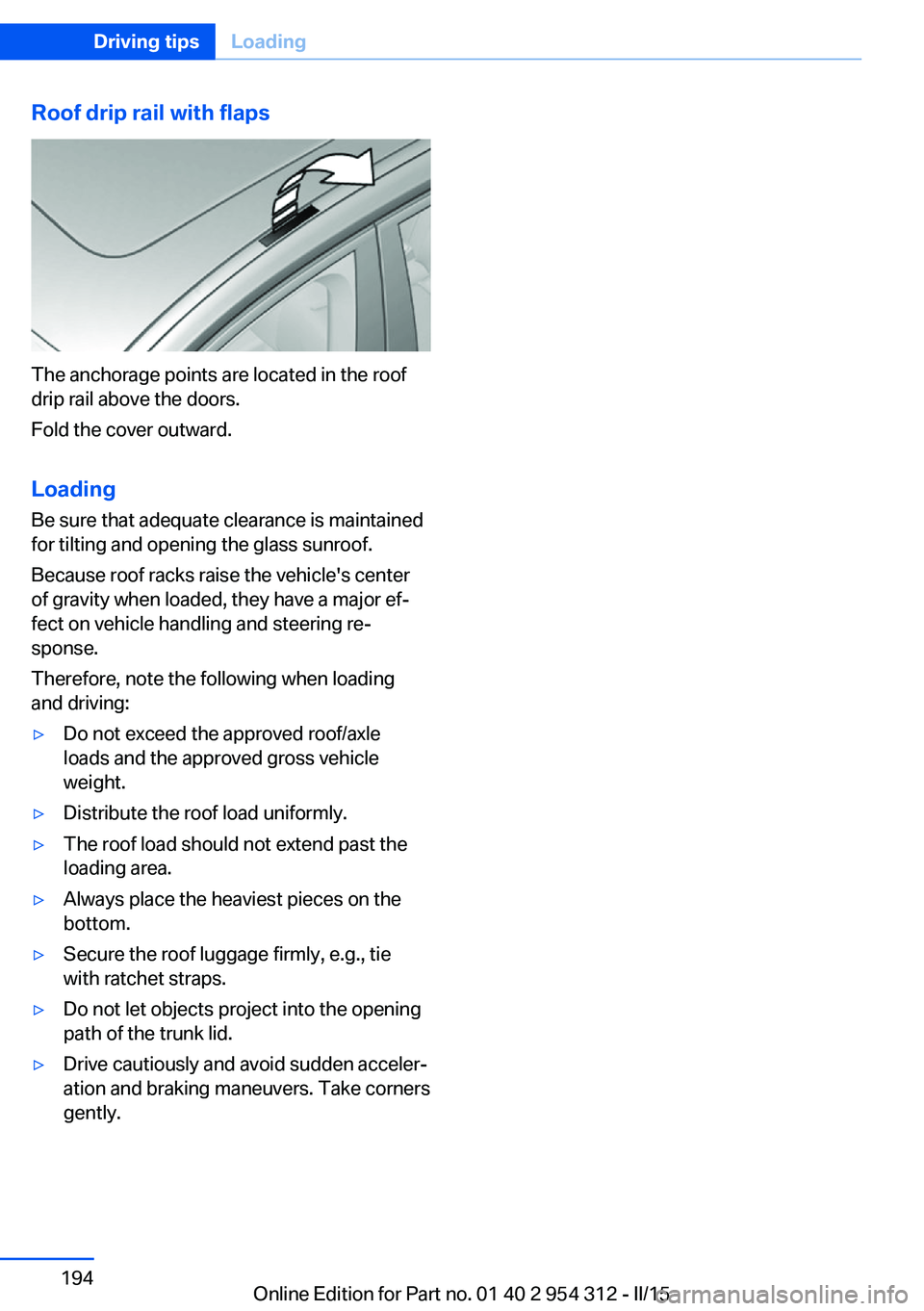
The anchorage points are located in the roof
drip rail above the doors.
Fold the cover outward.
Loading Be sure that adequate clearance is maintained
for tilting and opening the glass sunroof.
Because roof racks raise the vehicle's center
of gravity when loaded, they have a major ef‐
fect on vehicle handling and steering re‐
sponse.
Therefore, note the following when loading
and driving:
▷Do not exceed the approved roof/axle
loads and the approved gross vehicle
weight.▷Distribute the roof load uniformly.▷The roof load should not extend past the
loading area.▷Always place the heaviest pieces on the
bottom.▷Secure the roof luggage firmly, e.g., tie
with ratchet straps.▷Do not let objects project into the opening
path of the trunk lid.▷Drive cautiously and avoid sudden acceler‐
ation and braking maneuvers. Take corners
gently.Seite 194Driving tipsLoading194
Online Edition for Part no. 01 40 2 954 312 - II/15
Page 229 of 277
into the tires, which seals the damage from the
inside.
The compressor can be used to check the tire
inflation pressure.
Hints▷Follow the instructions on using the Mobi‐
lity System found on the compressor and
sealant container.▷Use of the Mobility System may be ineffec‐
tive if the tire puncture measures approx.
1/8 in/4 mm or more.▷Contact the nearest service center if the
tire cannot be made drivable.▷If possible, do not remove foreign bodies
that have penetrated the tire.▷Pull the speed limit sticker off the sealant
container and apply it to the steering
wheel.▷The use of a sealant can damage the TPM
wheel electronics. In this case, have the
electronics checked at the next opportu‐
nity and have them replaced if needed.
Enclosed areas
Do not let the engine run in enclosed
areas, since breathing in exhaust fumes may
lead to loss of consciousness and death. The
exhaust gases contain carbon monoxide, an
odorless and colorless but highly toxic gas.◀
Storage The Mobility System is located under the
cargo floor panel.
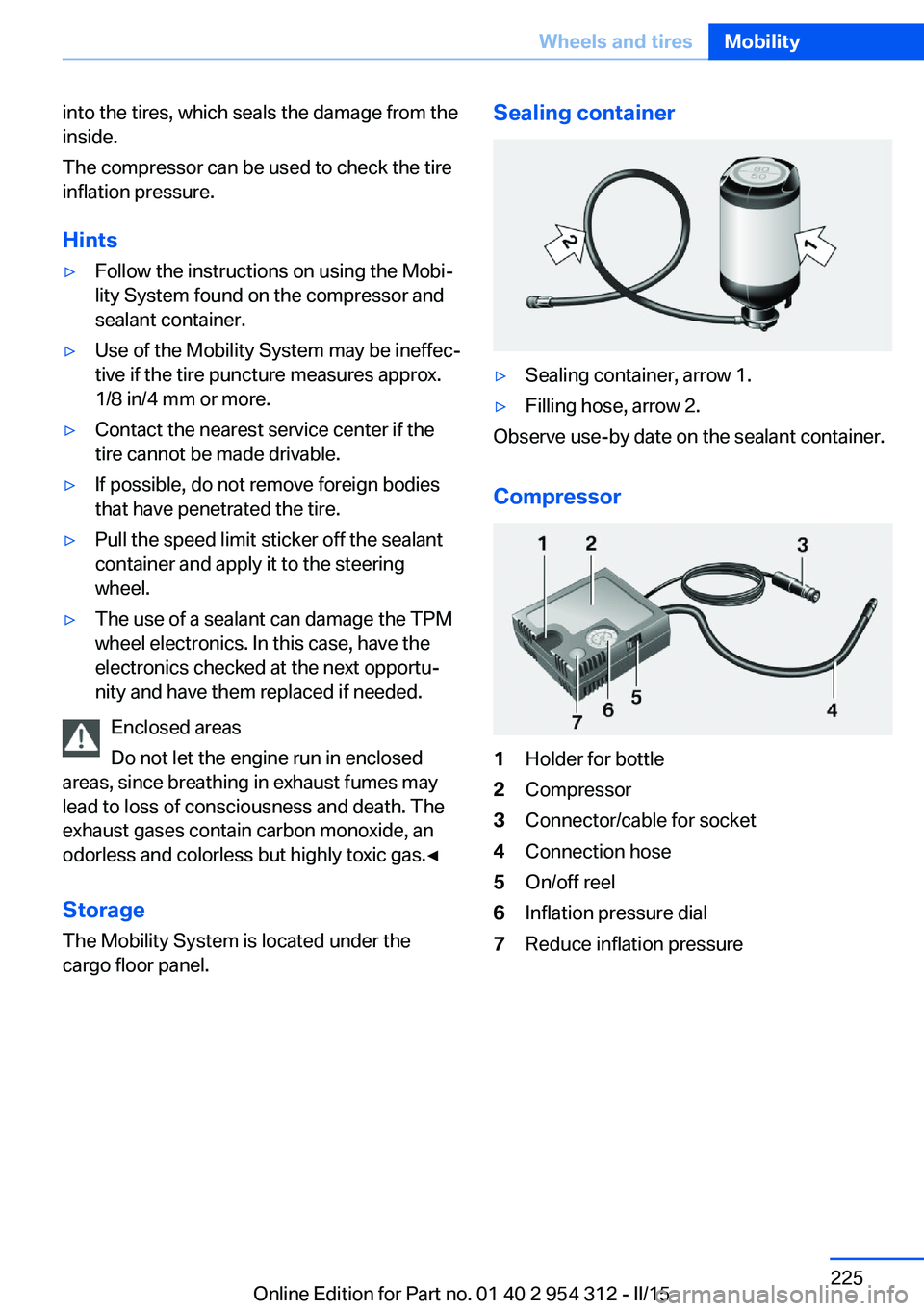
Sealing container▷Sealing container, arrow 1.▷Filling hose, arrow 2.
Observe use-by date on the sealant container.
Compressor
1Holder for bottle2Compressor3Connector/cable for socket4Connection hose5On/off reel6Inflation pressure dial7Reduce inflation pressureSeite 225Wheels and tiresMobility225
Online Edition for Part no. 01 40 2 954 312 - II/15
Page 232 of 277
Snow chains
Fine-link snow chains Only certain types of fine-link snow chains
have been tested by the manufacturer of the
vehicle, classified as road-safe and approved.
Information about the approved snow chains
are available from the service center.
Use Use only in pairs on the rear wheels, equipped
with the tires of the following size:▷225/55 R 17.▷245/45 R 18.▷245/40 R 19.
Follow the snow chain manufacturer's instruc‐
tions.
Make sure that the snow chains are always
sufficiently tight. Retighten as needed accord‐
ing to the chain manufacturer's instructions.
Do not initialize the Flat Tire Monitor after
mounting snow chains, as doing so may result
in incorrect readings.
Do not initialize the Tire Pressure Monitor after
mounting snow chains, as doing so may result
in incorrect readings.
When driving with snow chains, briefly activate
Dynamic Traction Control if needed.
Maximum speed with snow chains Do not exceed a speed of 30 mph/50 km/hwhen using snow chains.
Snow chain detection
The concept When using snow chains, settings should bemade via the iDrive for the snow chains being
applied.
The snow chain detection system supports
you by automatically showing the detected
state on the Control Display.
When snow chains are in use, the rear axle
steering of the Integral Active Steering is deac‐
tivated automatically.
At speeds above the maximum permitted
speed with snow chains of 30 mph/50 km/h,
the rear axle steering is activated again auto‐
matically.
Activating the status1."Settings"2."Tire chains"3."Tire chains installed"
Automatic detection If functioning properly:
▷Snow chains are mounted. Settings are not
activated
.
After you drive a short distance, a Check
Control message is shown and the state is
activated automatically.
Confirm the automatic activation.
▷Snow chains are not mounted. Settings are
activated
.
At speeds above 30 mph/50 km/h, a Check
Control message is displayed. Deactivate
the status manually.
If not functioning properly:
▷Snow chains are mounted. Settings are not
activated
.
A Check Control message is not displayed.
The automatic detection system is mal‐
functioning. Activate the status manually.
Activating/deactivating rear axle
steering
If the status indicating that snow chains are in
use is activated, the rear axle steering is deac‐
tivated automatically.
At speeds above 30 mph/50 km/h, the rear axle
steering is activated again, even though snow
chains are in use.
Seite 228MobilityWheels and tires228
Online Edition for Part no. 01 40 2 954 312 - II/15