2015 BMW 5 SERIES GRAN TURISMO Wheels
[x] Cancel search: WheelsPage 119 of 263
reported though tire inflation pressures are
correct.
The tire inflation pressure depends on the
tire's temperature. Driving or exposure to the
sun will increase the tire's temperature, thus
increasing the tire inflation pressure. The tire
inflation pressure is reduced when the tire
temperature falls again. These circumstances
may cause a warning when temperatures fall
very sharply.
Malfunction The yellow warning lamp flashes and
then lights up continuously. A Check
Control message is displayed. No flat
tire or loss of tire inflation pressure can be de‐
tected.
Display in the following situations:▷A wheel without TPM electronics is fitted:
have the service center check it if needed.▷Malfunction: have the system checked by
your service center.▷TPM was unable to complete the reset.
Reset the system again.▷Interference through systems or devices
with the same radio frequency: after leav‐
ing the area of the interference, the system
automatically becomes active again.
Declaration according to NHTSA/
FMVSS 138 Tire Pressure Monitoring
System
Each tire, including the spare (if provided)
should be checked monthly when cold and in‐
flated to the inflation pressure recommended
by the vehicle manufacturer on the vehicle
placard or tire inflation pressure label. (If your
vehicle has tires of a different size than the size
indicated on the vehicle placard or tire inflation
pressure label, you should determine the
proper tire inflation pressure for those tires.)
As an added safety feature, your vehicle has
been equipped with a tire pressure monitoring
system (TPMS) that illuminates a low tire pres‐
sure telltale when one or more of your tires is
significantly under-inflated. Accordingly, when
the low tire pressure telltale illuminates, you
should stop and check your tires as soon as
possible, and inflate them to the proper pres‐
sure. Driving on a significantly under-inflated
tire causes the tire to overheat and can lead to
tire failure. Under-inflation also reduces fuel ef‐
ficiency and tire tread life, and may affect the
vehicle's handling and stopping ability. Please
note that the TPMS is not a substitute for
proper tire maintenance, and it is the driver's
responsibility to maintain correct tire pressure,
even if under-inflation has not reached the
level to trigger illumination of the TPMS low
tire pressure telltale. Your vehicle has also
been equipped with a TPMS malfunction indi‐
cator to indicate when the system is not oper‐
ating properly. The TPMS malfunction indica‐
tor is combined with the low tire pressure
telltale. When the system detects a malfunc‐
tion, the telltale will flash for approximately one
minute and then remain continuously illumi‐
nated. This sequence will continue upon sub‐
sequent vehicle start-ups as long as the mal‐
function exists. When the malfunction indicator
is illuminated, the system may not be able to
detect or signal low tire pressure as intended.
TPMS malfunctions may occur for a variety of
reasons, including the installation of replace‐
ment or alternate tires or wheels on the vehicle
that prevent the TPMS from functioning prop‐
erly. Always check the TPMS malfunction tell‐
tale after replacing one or more tires or wheels
on your vehicle to ensure that the replacement
or alternate tires and wheels allow the TPMS
to continue to function properly.
Intelligent Safety The conceptIntelligent Safety enables central operation of
the driver assistance system.
Depending on how the vehicle is equipped, In‐
telligent Safety consists of one or more sys‐Seite 115SafetyControls115
Online Edition for Part no. 01 40 2 954 285 - II/15
Page 138 of 263
Driving stability control systemsVehicle features and optionsThis chapter describes all standard, country-
specific and optional features offered with the
series. It also describes features that are not
necessarily available in your car, e. g., due to
the selected options or country versions. This
also applies to safety-related functions and
systems. The respectively applicable country
provisions must be observed when using the
respective features and systems.
Antilock Brake System ABS ABS prevents locking of the wheels during
braking.
The vehicle contains its steering power even
during full brake applications, thus increasing
active safety.
ABS is operational every time you start the en‐
gine.
Brake assistant When you apply the brakes rapidly, this system
automatically produces the greatest possible
braking force boost. It reduces the braking dis‐
tance to a minimum during emergency stop.
This system utilizes all of the benefits provided
by ABS.
Do not reduce the pressure on the brake pedal
for the duration of the emergency stop.
Adaptive brake assistant In combination with the Active Cruise Control,
this system ensures that the brakes respond
even more rapidly when braking in critical sit‐
uations.Drive-off assistant
This system supports driving off on inclines.
The parking brake is not required.1.Hold the vehicle in place with the foot
brake.2.Release the foot brake and drive off with‐
out delay.
After the foot brake is released, the vehicle is
held in place for approx. 2 seconds.
Depending on the vehicle load or when a trailer
is used, the vehicle may roll back slightly.
Driving off without delay
After releasing the foot brake, start driv‐
ing without delay, since the drive-off assistant
will not hold the vehicle in place for more than
approx. 2 seconds and the vehicle will begin to
roll back.◀
DSC Dynamic Stability
Control
The concept DSC prevents traction loss in the power
wheels when driving off and accelerating.
DSC also recognizes unstable vehicle condi‐
tions such as fishtailing or nose-diving. Within
the physical limits DSC helps to keep the vehi‐
cle on a steady course by reducing engine
speed and by applying brakes to the individual
wheels.
Note Adjust your driving style to the situation
An appropriate driving style is always the
responsibility of the driver.
The laws of physics cannot be repealed, not
even with DSC.
Seite 134ControlsDriving stability control systems134
Online Edition for Part no. 01 40 2 954 285 - II/15
Page 142 of 263
COMFORT/ECO PROBalanced tuning.
COMFORT+ Comfort-oriented tuning of the shock absorb‐
ers for optimal traveling comfort.
Integral Active Steering The concept
Integral Active Steering is a combination of Ac‐
tive Steering and rear axle steering.
Active Steering varies the steering angle of the
wheels in relation to the steering wheel move‐
ment as a function of the speed.
At speeds up to approx. 37 mph/60 km/h, e.g.,
in curves, the steering angle is increased, i.e.,
steering becomes more direct.
The rear axle steering acts to increase maneu‐
verability by turning the rear wheels slightly in
a direction opposite to the front wheels.
At higher speeds, the steering angle is increas‐
ingly reduced.
The rear wheels are turned to the same angle
as the front wheels.
In critical situations, Integral Active Steering
can specifically steer the front and rear wheels
to stabilize the vehicle before the driver inter‐
venes, e.g., when braking where road condi‐
tions differ on the left and right sides of the ve‐
hicle.
InitializingIn rare cases, it may become necessary to initi‐
alize the Integral Active Steering.
The warning lamp lights up. A Check
Control message is displayed.1.With the engine running, turn the steering
wheel all the way to the left and right sev‐
eral times in a uniform manner until the
warning lamp disappears.2.Have the system checked if the warning
lamp does not go out after moving the
steering wheel approx. 6 times or if the
steering wheel is at an angle.
Using snow chains
Note When snow chains are in use, refer to
page 215, rear wheel steering is deactivated.
Programs The system offers several different programs.
Select the programs via the Driving Dynamics
Control, refer to page 139.
SPORT
Consistently sporty tuning of the Integral Ac‐
tive Steering for greater driving agility.
COMFORT Balanced tuning between the COMFORT+ and
SPORT programs.
COMFORT+
Consistently comfort-oriented tuning of the In‐
tegral Active Steering for optimal traveling
comfort.
Malfunction
In the event of a malfunction, the steering
wheel must be turned further, while the vehicle
responds more sensitively to steering wheel
movements in the higher speed range.
The stability-enhancing intervention may be
deactivated.
Proceed cautiously and drive defensively.
Have the system checked.
Seite 138ControlsDriving stability control systems138
Online Edition for Part no. 01 40 2 954 285 - II/15
Page 163 of 263
track line is continuously adjusted for the
steering wheel movement.
"Parking aid lines"
Turning circle and pathway lines are displayed.
System limits
Top View cannot be used in the following sit‐
uations:
▷With a door open.▷With the tailgate open.▷With an exterior mirror folded in.▷In poor light.
A Check Control message is displayed in some
of these situations.
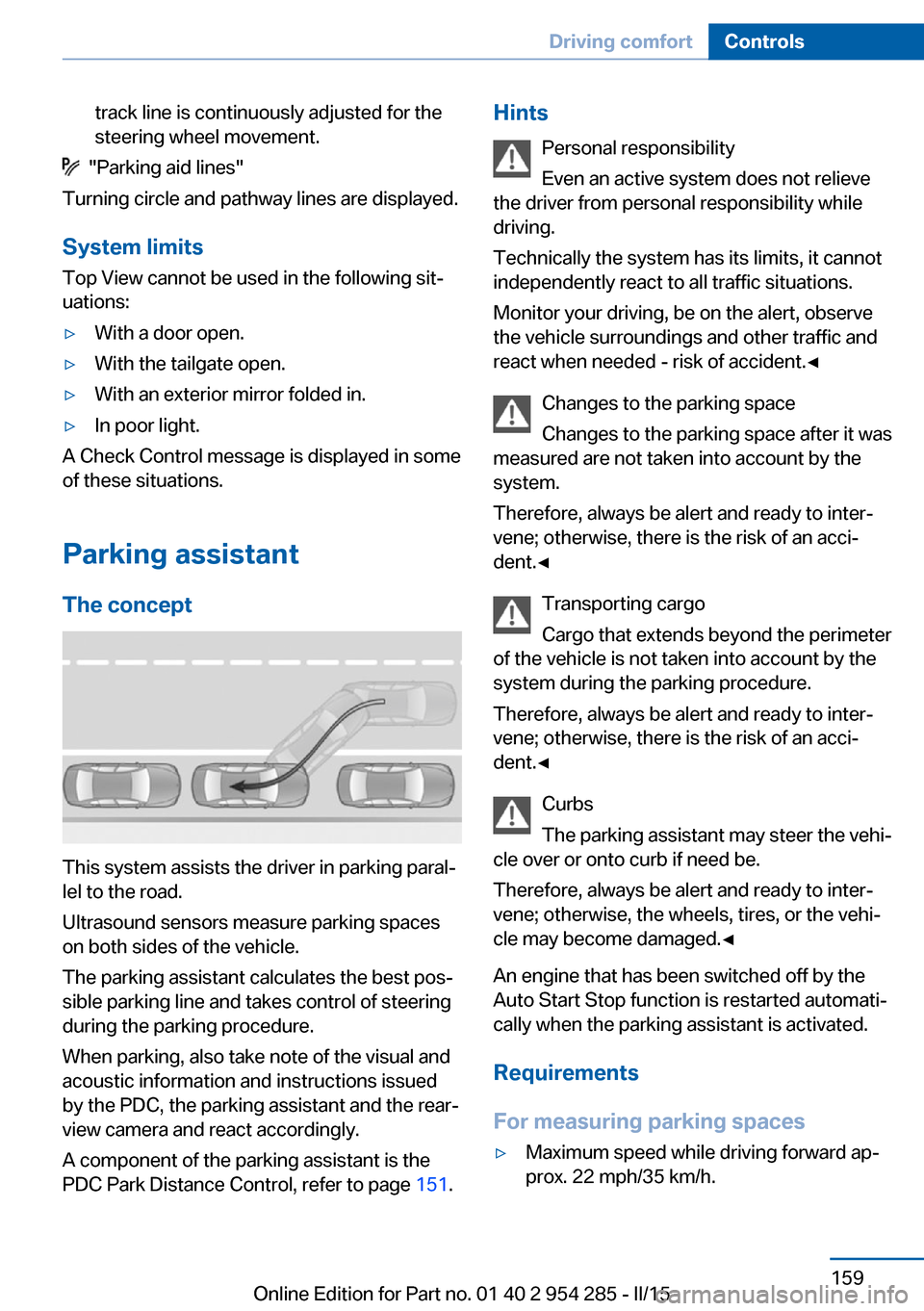
Parking assistant The concept
This system assists the driver in parking paral‐
lel to the road.
Ultrasound sensors measure parking spaces
on both sides of the vehicle.
The parking assistant calculates the best pos‐
sible parking line and takes control of steering
during the parking procedure.
When parking, also take note of the visual and
acoustic information and instructions issued
by the PDC, the parking assistant and the rear‐
view camera and react accordingly.
A component of the parking assistant is the
PDC Park Distance Control, refer to page 151.
Hints
Personal responsibility
Even an active system does not relieve
the driver from personal responsibility while
driving.
Technically the system has its limits, it cannot
independently react to all traffic situations.
Monitor your driving, be on the alert, observe
the vehicle surroundings and other traffic and
react when needed - risk of accident.◀
Changes to the parking space
Changes to the parking space after it was
measured are not taken into account by the system.
Therefore, always be alert and ready to inter‐
vene; otherwise, there is the risk of an acci‐
dent.◀
Transporting cargo
Cargo that extends beyond the perimeter
of the vehicle is not taken into account by the
system during the parking procedure.
Therefore, always be alert and ready to inter‐
vene; otherwise, there is the risk of an acci‐
dent.◀
Curbs
The parking assistant may steer the vehi‐
cle over or onto curb if need be.
Therefore, always be alert and ready to inter‐
vene; otherwise, the wheels, tires, or the vehi‐
cle may become damaged.◀
An engine that has been switched off by the
Auto Start Stop function is restarted automati‐
cally when the parking assistant is activated.
Requirements
For measuring parking spaces▷Maximum speed while driving forward ap‐
prox. 22 mph/35 km/h.Seite 159Driving comfortControls159
Online Edition for Part no. 01 40 2 954 285 - II/15
Page 170 of 263
Residual heat
The heat stored in the engine is used to heat
the interior.
Functional requirement▷Up to 15 minutes after switching off the
engine.▷Warm engine.▷The battery is sufficiently charged.▷External temperature below 77 ℉/25 ℃.
The availability of the function is shown on the
display of the automatic climate control.
Switching on
1.Switch off the ignition.2. Press the right side of the button
on the driver's side.
The symbol appears on the automatic cli‐
mate Control Display.
The interior temperature, air volume and air
distribution can be adjusted with the ignition
switched on.
Switch off
At the lowest fan speed, press the left side of
the button on the driver's side.
The symbol on the display of the automatic
climate control flashes.
Switching the system on/off Switch off
▷Complete system: Press and hold the left button on
the driver's side until the control
clicks off.▷On the front passenger side:
Press and hold the left button on
the front passenger side.Switching on
Press any button except:▷Rear window defroster.▷Left side of Air volume button.▷Seat heating.▷Seat ventilation.▷If necessary, SYNC program.
Microfilter/activated-charcoal filter
The microfilter removes dust and pollen from
the incoming air.
The activated-charcoal filter removes gaseous
pollutants from the outside air that enters the
vehicle.
This combined filter should be replaced during
scheduled maintenance, refer to page 223, of
your vehicle.
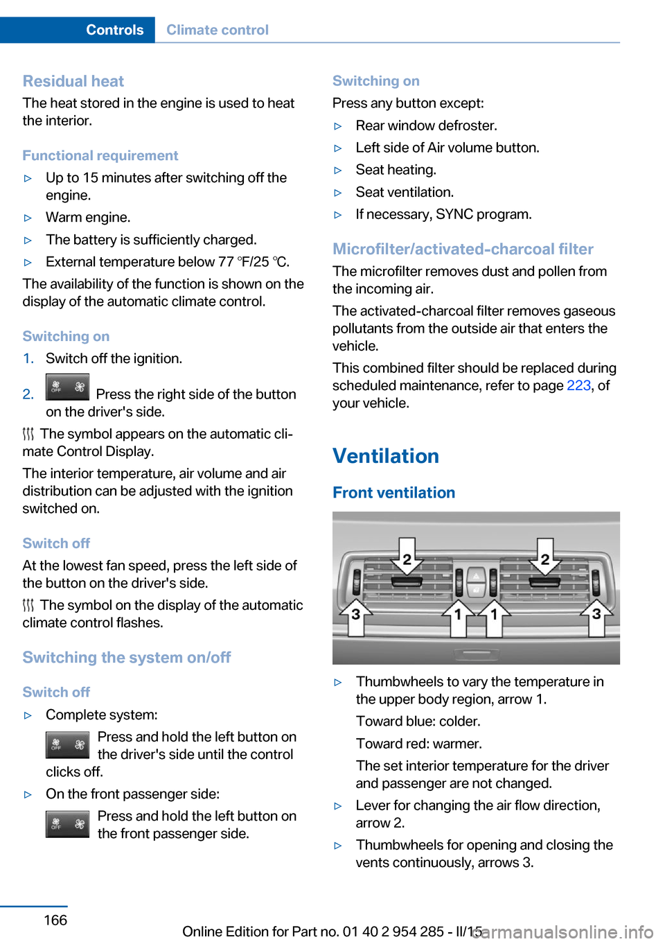
Ventilation Front ventilation
▷Thumbwheels to vary the temperature in
the upper body region, arrow 1.
Toward blue: colder.
Toward red: warmer.
The set interior temperature for the driver
and passenger are not changed.▷Lever for changing the air flow direction,
arrow 2.▷Thumbwheels for opening and closing the
vents continuously, arrows 3.Seite 166ControlsClimate control166
Online Edition for Part no. 01 40 2 954 285 - II/15
Page 171 of 263
Ventilation levels▷Draft-free ventilation:
Thumbwheel, arrow 3, in level
: the air
current is fanned out.
▷Maximum air flow:
Thumbwheel, arrow 3, in level
: the air
is partially fanned out and partially bundled.
This maximizes the air supply.
▷Direct ventilation:
Thumbwheel, arrow 3, in level
: the air
is bundled and can be directed to a specific
point.
Adjusting the ventilation
▷Ventilation for cooling:
Direct vent in your direction when vehicle's
interior is too hot.▷Draft-free ventilation:
Adjust the vent to let the air flow past you.
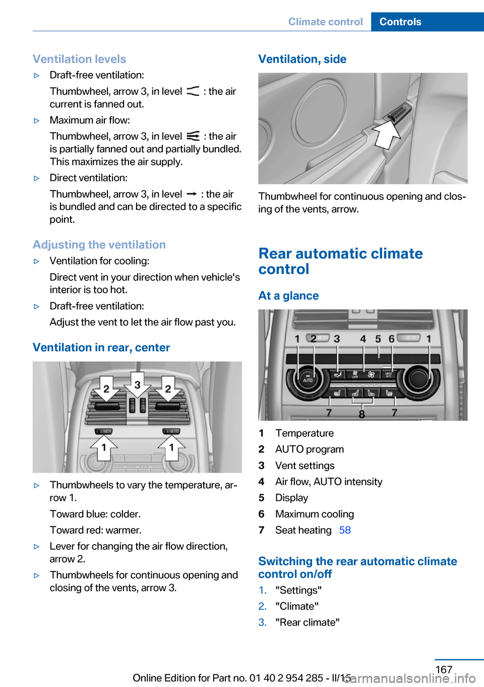
Ventilation in rear, center
▷Thumbwheels to vary the temperature, ar‐
row 1.
Toward blue: colder.
Toward red: warmer.▷Lever for changing the air flow direction,
arrow 2.▷Thumbwheels for continuous opening and
closing of the vents, arrow 3.Ventilation, side
Thumbwheel for continuous opening and clos‐
ing of the vents, arrow.
Rear automatic climate
control
At a glance
1Temperature2AUTO program3Vent settings4Air flow, AUTO intensity5Display6Maximum cooling7Seat heating 58
Switching the rear automatic climate
control on/off
1."Settings"2."Climate"3."Rear climate"Seite 167Climate controlControls167
Online Edition for Part no. 01 40 2 954 285 - II/15
Page 203 of 263
Mobility
In order to always ensure your mobility, you will find important information on operating fluids,wheels and tires, maintenance and Roadside Assistance in the following.Online Edition for Part no. 01 40 2 954 285 - II/15
Page 208 of 263
Wheels and tiresVehicle features and options
This chapter describes all standard, country-
specific and optional features offered with the
series. It also describes features that are not
necessarily available in your car, e. g., due to
the selected options or country versions. This
also applies to safety-related functions and
systems. The respectively applicable country
provisions must be observed when using the
respective features and systems.
Tire inflation pressure Safety information
The tire characteristics and tire inflation pres‐
sure influence the following:▷The service life of the tires.▷Road safety.▷Driving comfort.
Checking the tire inflation pressure
Check the tire inflation pressure regularly
Regularly check the tire inflation pres‐
sure, and correct it as needed: at least twice a
month and before a long trip. If you fail to ob‐
serve this precaution, you may be driving on
tires with incorrect tire pressures, a condition
that may not only compromise your vehicle's
driving stability, but also lead to tire damage
and the risk of an accident.◀
Tires have a natural, consistent loss of tire in‐
flation pressure.
Tires heat up while driving, and the tire infla‐
tion pressure increases along with the tire's
temperature. The tire inflation pressure speci‐
fications relate to cold tires or tires with the
ambient temperature.
Only check the tire inflation pressure when the
tires are cold. This means after driving no more
than 1.25 miles/2 km or when the vehicle has
been parked for at least 2 hours.
The displays of inflation devices may under-
read by up to 1.45 psi/0.1 bar.
For Flat Tire Monitor: after correcting the tire
inflation pressure, reinitialize the Flat Tire
Monitor.
For Tire Pressure Monitor: after correcting the
tire inflation pressure, reset the Tire Pressure
Monitor.
Tire inflation pressure specifications
The tire inflation pressure table, refer to
page 205, contains all tire inflation pressure
specifications for the specified tire sizes at the
ambient temperature. Tire inflation pressure
specifications apply to approved tire sizes and
recommended tire brands. This information
can be obtained from your service center.
To identify the correct tire inflation pressure,
please note the following:▷Tire sizes of your vehicle.▷Maximum permitted driving speed.
Tire inflation pressures up to
100 mph/160 km/h
For speeds of up to 100 mph/160 km/h and for
optimum driving comfort, note the pressure
values in the tire inflation pressure table, refer
to page 205, and adjust as necessary.
Seite 204MobilityWheels and tires204
Online Edition for Part no. 01 40 2 954 285 - II/15