2015 BMW 2 SERIES CONVERTIBLE flat tire
[x] Cancel search: flat tirePage 185 of 234

If work is not carried out properly, there is a
danger of subsequent damage and related
safety hazards.◀
Wheel and tire combination
You can ask the service center about the right
wheel/tire combination and wheel rim versions
for the vehicle.
Incorrect wheel and tire combinations impair
the function of a variety of systems such as
ABS or DSC.
To maintain good handling and vehicle re‐
sponse, use only tires with a single tread con‐
figuration from a single manufacturer.
Following tire damage, have the original wheel
and tire combination remounted on the vehicle
as soon as possible.
Approved wheels and tires
You should only use wheels and tires
that have been approved by the vehicle manu‐
facturer for your vehicle type; otherwise, e.g.,
despite having the same official size ratings,
variations can lead to chassis contact and with
it, the risk of severe accidents
The manufacturer of your vehicle cannot eval‐
uate non-approved wheels and tires to deter‐
mine if they are suited for use, and therefore
cannot guarantee the operating safety of the
vehicle.◀
Recommended tire brands
For each tire size, the manufacturer of your ve‐
hicle recommends certain tire brands. These
can be identified by a star on the tire sidewall.
With proper use, these tires meet the highest
standards for safety and handling.
New tires Tire traction is not optimal due to manufactur‐
ing circumstances when tires are brand-new;
they achieve their full traction potential after a
break-in time.
Drive conservatively for the first
200 miles/300 km.
Retreaded tires
The manufacturer of your vehicle does not rec‐
ommend the use of retreaded tires.
Retreaded tires
Possibly substantial variations in the de‐
sign and age of the tire casing structures can
limit service life and have a negative impact on
road safety.◀
Winter tires
Winter tires are recommended for operating on
winter roads.
Although so-called all-season M+S tires pro‐
vide better winter traction than summer tires,
they do not provide the same level of perform‐
ance as winter tires.
Maximum speed of winter tires
If the maximum speed of the vehicle is higher
than the permissible speed for the winter tires,
then a respective symbol is displayed in your
field of vision. You can obtain this sign from the
tire specialist or from your service center.
Maximum speed for winter tires
Do not exceed the maximum speed for
the respective winter tires; otherwise, tire dam‐
age and accidents can occur.◀
Run-flat tiresIf you are already using run-flat tires, for your
own safety you should replace them only withSeite 181Wheels and tiresMobility181
Online Edition for Part no. 01 40 2 959 847 - II/15
Page 186 of 234

the same kind. No spare tire is available in the
case of a flat tire. Your service center will be
glad to advise you.
Rotating wheels between axles Different wear patterns can occur on the front
and rear axles depending on individual driving
conditions. The tires can be rotated between
the axles to achieve even wear. Your service
center will be glad to advise you. After rotating,
check the tire pressure and correct if needed.
Rotating the tires is not permissible on vehi‐
cles with different tire sizes or rim sizes on the
front and rear axles.
StorageStore wheels and tires in a cool, dry place with
as little exposure to light as possible.
Always protect tires against all contact with oil,
grease and fuels.
Do not exceed the maximum tire inflation pres‐
sure indicated on the side wall of the tire.
Run-flat tires Label
RSC label on the tire sidewall.
The wheels consist of tires that are self-sup‐
porting, to a limited degree, and possibly spe‐
cial rims.
The support of the sidewall allows the tire to
remain drivable to a restricted degree in the
event of a tire inflation pressure loss.
Follow the instructions for continued driving
with a flat tire.
Changing run-flat tires
For your own safety, only use run-flat tires. No
spare tire is available in the case of a flat tire.
Your service center will be glad to advise you.
Mobility System
The concept With the Mobility System, minor tire damagecan be sealed quickly to enable continued
travel. To accomplish this, sealant is pumped
into the tires, which seals the damage from the inside.
The compressor can be used to check the tire inflation pressure.
Hints▷Follow the instructions on using the Mobi‐
lity System found on the compressor and
sealant container.▷Use of the Mobility System may be ineffec‐
tive if the tire puncture measures approx.
1/8 in/4 mm or more.▷Contact the nearest service center if the
tire cannot be made drivable.▷If possible, do not remove foreign bodies
that have penetrated the tire.▷Pull the speed limit sticker off the sealant
container and apply it to the steering
wheel.▷The use of a sealant can damage the TPM
wheel electronics. In this case, have the
electronics checked at the next opportu‐
nity and have them replaced if needed.
Enclosed areas
Do not let the engine run in enclosed
areas, since breathing in exhaust fumes may
lead to loss of consciousness and death. The
Seite 182MobilityWheels and tires182
Online Edition for Part no. 01 40 2 959 847 - II/15
Page 187 of 234

exhaust gases contain carbon monoxide, an
odorless and colorless but highly toxic gas.◀
Storage The Mobility System is located under the
cargo floor panel.
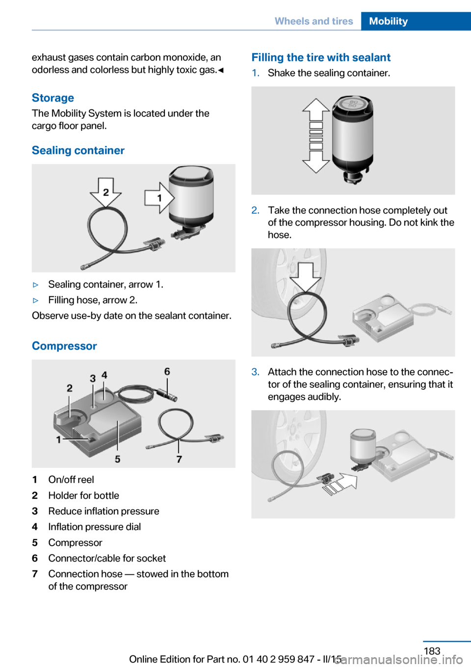
Sealing container▷Sealing container, arrow 1.▷Filling hose, arrow 2.
Observe use-by date on the sealant container.
Compressor
1On/off reel2Holder for bottle3Reduce inflation pressure4Inflation pressure dial5Compressor6Connector/cable for socket7Connection hose — stowed in the bottom
of the compressorFilling the tire with sealant1.Shake the sealing container.2.Take the connection hose completely out
of the compressor housing. Do not kink the
hose.3.Attach the connection hose to the connec‐
tor of the sealing container, ensuring that it
engages audibly.Seite 183Wheels and tiresMobility183
Online Edition for Part no. 01 40 2 959 847 - II/15
Page 188 of 234

4.Slide the sealing container upright into the
holder on the compressor housing, ensur‐
ing that it engages audibly.5.Screw the connection hose onto the tire
valve of the defective wheel.6.With the compressor switched off, insert
the plug into a power socket inside the ve‐
hicle.7.With the ignition turned on or the engine
running, reel on the compressor.
Switch off the compressor after 10 mi‐
nutes
Do not allow the compressor to run longer than
10 minutes; otherwise, the device will overheat
and may be damaged.◀
Let the compressor run for approx. 3 to 8 mi‐
nutes to fill the tire with sealant and achieve a
tire inflation pressure of approx. 2.5 bar.
While the tire is being filled with sealant, the
tire inflation pressure may sporadically reach
approx. 5 bar. Do not reel off the compressor at
this point.
If a tire inflation pressure of 2 bar is not
reached:
1.Switch off the compressor.2.Unscrew the filling hose from the wheel.3.Drive 33 ft/10 m forward and back to dis‐
tribute the sealant in the tire.4.Inflate the tire again using the compressor.
If a tire inflation pressure of 2 bar cannot be
reached, contact your service center.
Stowing the Mobility System
1.Remove the connection hose of the seal‐
ant container from the wheel.2.Remove the connection hose from the
sealant container.Seite 184MobilityWheels and tires184
Online Edition for Part no. 01 40 2 959 847 - II/15
Page 189 of 234

3.Wrap the empty sealant container and con‐
nection hose in suitable material to avoid
dirtying the cargo area.4.Stow the Mobility System back in the vehi‐
cle.
Distributing the sealant
Immediately drive approx. 5 miles/10 km to en‐
sure that the sealant is evenly distributed in the
tire.
Do not exceed a speed of 50 mph/80 km/h.
If possible, do not drive at speeds less than
12 mph/20 km/h.
To correct the tire inflation pressure
1.Stop at a suitable location.2.Screw the connection hose onto the tire
valve stem.3.Attach the connection hose directly to the
compressor.4.Insert the connector into a power socket
inside the vehicle.5.Correct the tire inflation pressure to
2.5 bar.▷Increase pressure: with the ignition
turned on or the engine running, reel
on the compressor.▷To reduce the pressure: press the but‐
ton on the compressor.
Continuing the trip
Do not exceed the maximum permissible
speed of 50 mph/80 km/h.
Reinitialize the Flat Tire Monitor.
Reinitialize the Tire Pressure Monitor.
Replace the defective tire and the sealant con‐
tainer of the Mobility System as soon as possi‐
ble.
Snow chains Fine-link snow chains
Only certain types of fine-link snow chains
have been tested by the manufacturer of the
vehicle, classified as road-safe and approved.
Information about the approved snow chains
are available from the service center.
Use
Use only in pairs on the rear wheels, equipped
with the tires of the following size:
▷205/55 R 16.Seite 185Wheels and tiresMobility185
Online Edition for Part no. 01 40 2 959 847 - II/15
Page 190 of 234

▷205/50 R 17.▷225/45 R 17.
Follow the snow chain manufacturer's instruc‐
tions.
Make sure that the snow chains are always
sufficiently tight. Retighten as needed accord‐
ing to the chain manufacturer's instructions.
Do not initialize the Flat Tire Monitor after
mounting snow chains, as doing so may result
in incorrect readings.
Do not initialize the Tire Pressure Monitor after
mounting snow chains, as doing so may result
in incorrect readings.
When driving with snow chains, briefly activate
Dynamic Traction Control if needed.
Maximum speed with snow chains Do not exceed a speed of 30 mph/50 km/hwhen using snow chains.
Seite 186MobilityWheels and tires186
Online Edition for Part no. 01 40 2 959 847 - II/15
Page 205 of 234

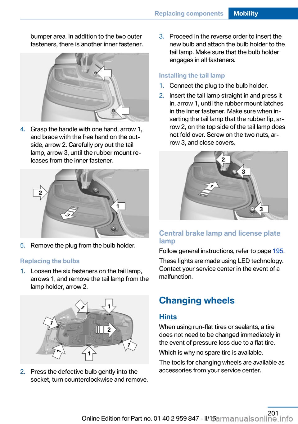
bumper area. In addition to the two outer
fasteners, there is another inner fastener.4.Grasp the handle with one hand, arrow 1,
and brace with the free hand on the out‐
side, arrow 2. Carefully pry out the tail
lamp, arrow 3, until the rubber mount re‐
leases from the inner fastener.5.Remove the plug from the bulb holder.
Replacing the bulbs
1.Loosen the six fasteners on the tail lamp,
arrows 1, and remove the tail lamp from the
lamp holder, arrow 2.2.Press the defective bulb gently into the
socket, turn counterclockwise and remove.3.Proceed in the reverse order to insert the
new bulb and attach the bulb holder to the
tail lamp. Make sure that the bulb holder
engages in all fasteners.
Installing the tail lamp
1.Connect the plug to the bulb holder.2.Insert the tail lamp straight in and press it
in, arrow 1, until the rubber mount latches
in the inner fastener. Make sure when in‐
serting the tail lamp that the rubber lip, ar‐
row 2, on the top side of the tail lamp does
not fold over. Screw on the two nuts, ar‐
row 3, and close covers.
Central brake lamp and license plate
lamp
Follow general instructions, refer to page 195.
These lights are made using LED technology.
Contact your service center in the event of a
malfunction.
Changing wheels
Hints
When using run-flat tires or sealants, a tire
does not need to be changed immediately in
the event of pressure loss due to a flat tire.
Which is why no spare tire is available.
The tools for changing wheels are available as
accessories from your service center.
Seite 201Replacing componentsMobility201
Online Edition for Part no. 01 40 2 959 847 - II/15
Page 225 of 234

Bulb replacement 195
Bulb replacement, front 196
Bulb replacement, rear 200
Bulbs and lights 195
Button, Start/Stop 67
Bypassing, refer to Jump- starting 205
C
California Proposition 65 Warning 7
Camera lenses, care 214
Camera, rearview cam‐ era 128
Can holder, refer to Cu‐ pholder 153
Car battery 202
Car care products 211
Care, displays 214
Care, vehicle 211
Cargo 159
Cargo area, enlarging 149
Cargo area partition 49
Cargo area, storage compart‐ ments 153
Cargo, securing 160
Cargo straps, securing cargo 160
Car key, refer to Remote con‐ trol 34
Carpet, care 213
Car wash 210
Catalytic converter, refer to Hot exhaust system 157
CBS Condition Based Serv‐ ice 193
CD/Multimedia, see user's manual for Navigation, En‐
tertainment and Communi‐
cation
Center armrest 152
Center console 16
Central locking system 40
Central screen, refer to Con‐ trol Display 18 Changes, technical, refer to
Safety 7
Changing parts 195
Changing wheels 201
Changing wheels/tires 180
Chassis number, see vehicle identification number 9
Check Control 81
Checking the oil level elec‐ tronically 189
Children, seating position 64
Children, transporting safely 64
Child restraint fixing sys‐ tem 64
Child restraint fixing system LATCH 66
Child restraint fixing systems, mounting 64
Child seat, mounting 64
Child seats 64
Chrome parts, care 213
Cigarette lighter 147
Cleaning displays 214
Climate control 135, 138
Clock 85
Closing/opening via door lock 39
Closing/opening with remote control 37
Coasting 165
Coasting with engine decou‐ pled, coasting 165
Coasting with idling en‐ gine 165
Cockpit 14
Combination reel, refer to Turn signals 71
Combination switch, refer to Wiper system 72
Comfort Access 41
COMFORT program, Dy‐ namic Driving Control 121
Compartments in the doors 152
Compass 145 Compressor 182
Condensation on win‐ dows 140
Condensation under the vehi‐ cle 158
Condition Based Service CBS 193
Configuring driving pro‐ gram 121
Confirmation signal 43
ConnectedDrive, see user's manual for Navigation, En‐
tertainment and Communi‐
cation
ConnectedDrive Services
Connecting electrical devi‐ ces 147
Continued driving with a flat tire 105 , 108
Control Display 18
Control Display, settings 91
Controller 18, 19
Control systems, driving sta‐ bility 117
Convenient closing with the remote control 38
Convenient opening with the remote control 37
Convertible, convertible top 47
Convertible mode, automatic climate control 136, 139
Convertible program, auto‐ matic climate con‐
trol 136 , 139
Convertible top 47
Convertible top, care 212
Convertible top, cargo area partition 49
Convertible top, emergency operation 49
Convertible top, rollover pro‐ tection system 102
Coolant 192
Coolant level 192
Coolant temperature 84 Seite 221Everything from A to ZReference221
Online Edition for Part no. 01 40 2 959 847 - II/15