Page 125 of 276

123
rOOF cArrYIn G SYS t EMS
Refer to the "Technical data -
"Dimensions" section for more
information on the length (L1 to L4) and the
height (H1 to H3) of the vehicle. Maximum load on the roof, evenly
distributed: 150 kg, for all versions,
within the vehicle's weight limit (Gross
Vehicle Weight).
For reasons of safety and to avoid damaging
the roof, it is essential to use a carrying
system (roof bars or roof rack) that is
approved for your vehicle.
Roof bars can only be fitted to an H1 or
H2
height van, combi and minibus versions.
On a minibus, check for the presence of roof
air conditioning units. The carrying system must always be
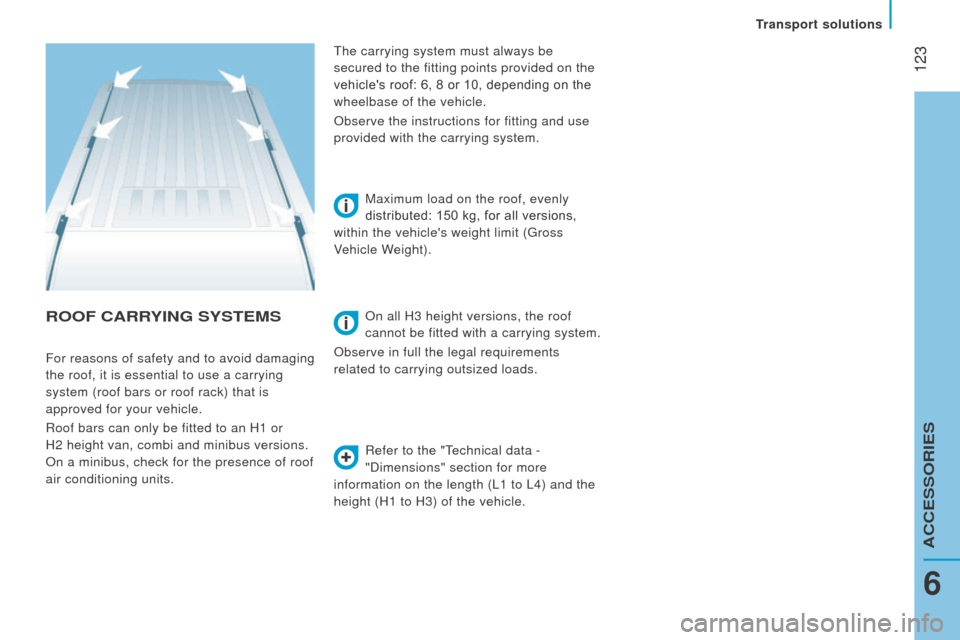
secured to the fitting points provided on the
vehicle's roof: 6, 8 or 10, depending on the
wheelbase of the vehicle.
Observe the instructions for fitting and use
provided with the carrying system.
On all H3 height versions, the roof
cannot be fitted with a carrying system.
Observe in full the legal requirements
related to carrying outsized loads.
6
Transport solutions
ACCESSORIES
Page 126 of 276

124
OtHEr AccESSOrIES
These accessories and parts, having been
tested and approved for reliability and
safety, are all adapted to your vehicle. A
wide range of recommended and genuine
parts is available.
"c omfort":
Air deflectors, insulated module, scented air
fresheners, reading lamp, cigarette lighter,
portable ashtray, non-slip seat cushions,
rear parking sensors...
"Protection":
Mats, mudflaps, vehicle protective cover,
seat covers, security grills for rear door
windows, twin rear security doors with
security locks, paint touch-up... "Security":
Anti-intrusion alarm, vehicle tracking system,
snow chains, non-slip covers, child seats,
first aid kit, warning triangle, high visibility
vest, fire extinguisher, pet safety belt, seat
belt cutter / glass hammer...
"Style":
Alloy wheels...
"Multimedia":
CD player, Wi-Fi on Board, semi-integral
satellite navigation system, hands-free kits,
driving aids, rear multimedia support, DVD
player, navigation mapping update, portable
satellite navigation systems, telephone
carrier, aftermarket digital radio, audio
systems...
"
t
ransport solutions":
T
owbars, towbar wiring harness with 7/13
connector, 7/7 connector, 13 connector,
interior protection kits, non-slip floor, wheel
arch protector, cab dividers, transverse roof
bars, roof racks, ladder for roof rack, roof
loading runners, loading plate for roof rack... Installation of radiocommunication
transmitters
You are advised to contact a CITROËN
dealer before installing accessory
radiocommunication transmitters with
external aerial on your vehicle.
CITROËN dealers can advise you on
the specifications (frequency waveband,
maximum output power, aerial position,
specific installation conditions) of the
transmitters which can be fitted, in
accordance with the Vehicle Electromagnetic
Compatibility Directive (2004/104/EC).
The fitting of electrical equipment or
accessories which are not listed by
CITROËN may result in the failure of your
vehicle's electronic system.
We request that you take note of this point
and recommend that you contact a dealer
to be shown the range of recommended
equipment and accessories.
Depending on the country in which the
vehicle is sold or operated, it may be
compulsory to have a high visibility vest,
warning triangle, replacement bulbs and
breathalyzer in the vehicle.
To prevent the mat from becoming
caught under the pedals:
-
ensure that the mat and its fixings are
positioned correctly,
-
never fit one mat on top of another
.
Equipment
Page 152 of 276

150
1 - Main beam headlamps
type
d , H7 - 55 W
-
Remove the cover by pulling on the
rubber tongue.
-
Disconnect the electrical connector
.
-
Release the retaining spring by pressing
on the central clip.
-
Change the bulb taking care to align the
metal part with the groove on the lamp. 2 -
d ipped beam headlamps
type
d , H7 - 55 W
-
Remove the cover by pulling on the
rubber tongue.
- Disconnect the electrical connector .
- Release the retaining spring by pressing
on the central clip.
-
Change the bulb taking care to align the
metal part with the grooves on the lamp.
Front lamps
3 - direction indicators
type A
, WY 21 W - 21 W
-
Remove the cover by pulling on the
rubber tongue.
-
T
urn the bulb holder a quarter turn
anticlockwise.
-
Change the bulb.
Open and secure the bonnet with the stay
.
To access the bulbs, reach behind the
headlamp unit.
If necessary you can remove the headlamp:
-
Depending on the country of sale,
remove the very low temperature
protection padding by sliding it towards
the outside of the vehicle.
-
Disconnect the electrical connector by
removing its locking ring.
-
Remove the two headlamp fixing
screws.
-
Move the headlamp towards the centre
of the vehicle to extract it from its
sliders. On the left hand side, take care not to
dislodge the bonnet stay.
Failed bulb or lamp
Page 154 of 276
152
courtesy lamps
type c , 12 V 10 W - 10 W
-
Press at the points indicated by the
arrows, then remove the courtesy lamp.
-
Open the protective flap.
-
Change the bulb moving aside the two
contacts.
-
Ensure that the new bulbs are secured
correctly between the two contacts.
-
Close the protective flap.
-
Fix the courtesy lamp in its housing and
ensure that it is secured correctly.
Side marker lamps
type A , W5W - 5W
-
If your vehicle is fitted with these lamps
(L4 body), remove the two fixing screws.
-
Pull the bulb holder to release it from the
lugs.
-
Pull the bulb out and change it.
direction indicator side
repeaters
type A , W 16 W F - 16 W
-
Move the mirror glass to access the
screws.
-
Remove the two fixing screws.
-
Pull the bulb holder to release it from the
lugs.
-
Pull the bulb out and change it. Front /
r ear
Failed bulb or lamp
Page 156 of 276
154
third brake lamp
type A, W5W - 5W (x 4)
-
Remove the two lamp fixing screws.
-
Remove the lamp by pulling it towards
you.
number plate lamps
type c , C5W - 5W
-
Press the point, indicated by the arrow
,
then remove the plastic lens.
-
Remove the failed bulb by moving aside
the two contacts.
-
With the new bulb in place, ensure that
it is secured correctly between the two
contacts.
-
Replace the plastic lens and press on it
to lock it in place. -
Remove the bulb holder by squeezing
the two tabs.
- Remove the failed bulb by pulling it out.
-
Change the bulb.
Failed bulb or lamp
Page 157 of 276
155
cHAnGInG A WIPE r BLA d E
The steps, located in the front bumper,
enable you to reach the blades and the
screenwash jets.changing a front wiper blade
Raise the wiper arm.
Unclip the blade by pressing the button and
remove it by pulling it outwards.
Fit the new blade and ensure that it is
secured correctly.
Return the wiper arm to the normal position.
Check that the screenwash or
headlamp wash jets are not blocked.
QUICK HELP
8
Worn wiper blade
Page 158 of 276

156
Parking the vehicle
Where possible, park the vehicle on level,
stable and non-slippery ground.
Apply the parking brake, switch off the
ignition and engage first gear.
Wear a high visibility vest and position the
warning triangle on the road.
You must ensure that the occupants get out
of the vehicle and wait in a safe location.
tools
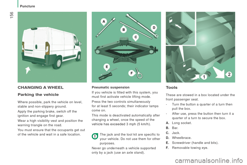
These are stowed in a box located under the
front passenger seat.
-
T
urn the button a quarter of a turn then
pull the box.
-
After use, press the button then turn it a
quarter of a turn to secure the box.
A.
Long socket.
B.
Bar.
c
. Jack.
d
. Wheelbrace.
E.
Screwdriver (handle and bits).
F.
Removable towing eye.
cHAnGInG A WHEELPneumatic suspension
If you vehicle is fitted with this system, you
must first activate vehicle lifting mode.
Press the two controls simultaneously
for at least 5 seconds; their indicator lamps
come on.
This mode is deactivated automatically after
changing a wheel, once the speed of the
vehicle has exceeded 3 mph (5 km/h).
The jack and the tool kit are specific to
your vehicle. Do not use them for other
purposes.
Never go underneath a vehicle supported
only by a jack (use an axle stand).
Puncture
Page 161 of 276
159
Fitting the spare wheelStowing the wheel
- Put the spare wheel in place on the hub
and fit the bolts by hand.
-
Pre-tighen the bolts using the
wheelbrace
d and the bar
B.
-
Lower the vehicle completely by folding
the jack
c
, then remove the jack.
-
T
ighten the bolts again using the
wheelbrace
d and the bar
B (tighten
them fully without forcing them). You must place the wheel to be repaired or
the spare wheel under the vehicle to secure
the carrier system.
-
Place the wheel at the rear of the vehicle.
●
For eversions with
steel wheels, hook
the carrier H on the outside.
●
Screw in the grip
G to secure the carrier
and wheel. ●
For versions with alloy wheels, position
the strap j
on the outside.
●
Fit the three strap fixing screws
I to the
alloy wheel.
QUICK HELP
8
Puncture