Page 73 of 98

PERIODIC MAINTENANCE AND ADJUSTMENT
6-31
6
EAU23292
Checking the wheel bearingsThe front and rear wheel bearings must
be checked at the intervals specified in
the periodic maintenance and lubrica-
tion chart. If there is play in the wheel
hub or if the wheel does not turn
smoothly, have a Yamaha dealer
check the wheel bearings.
EAU23315
BatteryA poorly maintained battery will cor-
rode and discharge quickly. The elec-
trolyte level, battery lead connections
and breather hose routing should be
checked before each ride and at the in-
tervals specified in the periodic main-
tenance and lubrication chart.
WARNING
EWA10771
Electrolyte is poisonous and
dangerous since it contains sul-
furic acid, which causes severe
burns. Avoid any contact with
skin, eyes or clothing and al-
ways shield your eyes when
working near batteries. In case
of contact, administer the fol-
lowing FIRST AID.
EXTERNAL: Flush with plenty
of water.
INTERNAL: Drink large quan-
tities of water or milk and im-
mediately call a physician.
EYES: Flush with water for 15
minutes and seek prompt
medical attention.
ZAUM1187
U5D7E5E0.book Page 31 Thursday, August 21, 2014 9:30 AM
Page 74 of 98

PERIODIC MAINTENANCE AND ADJUSTMENT
6-32
6Batteries produce explosive hy-
drogen gas. Therefore, keep
sparks, flames, cigarettes, etc.,
away from the battery and pro-
vide sufficient ventilation when
charging it in an enclosed
space.
Take care not to spill electrolyte
on the drive chain, as this may
weaken it, shorten chain life and
possibly result in an accident.
KEEP THIS AND ALL BATTER-
IES OUT OF THE REACH OF
CHILDREN.
To check the electrolyte level
1. Place the vehicle on a level sur-
face and hold it in an upright posi-
tion.TIPMake sure that the vehicle is posi-
tioned straight up when checking the
electrolyte level.2. Check the electrolyte level in the
battery.
TIPThe electrolyte should be between the
minimum and maximum level marks.3. If the electrolyte is at or below the
minimum level mark, add distilled
water to raise it to the maximum
level mark. NOTICE: Use only
distilled water, as tap water
contains minerals that are
harmful to the battery.
[ECA10612]
4. Check and, if necessary, tighten
the battery lead connections and
correct the breather hose routing.To store the battery
1. If the motorcycle will not be used
for more than one month, remove
the battery, fully charge it, and
then place it in a cool, dry place.
NOTICE: When removing the
battery, be sure the key is
turned to “OFF”, then discon-
nect the negative lead before
disconnecting the positive lead.
[ECA16303]
2. If the battery will be stored for
more than two months, check the
specific gravity of the electrolyte
at least once a month and fully
charge the battery whenever nec-
essary.
3. Fully charge the battery before in-
stallation. NOTICE: When install-
ing the battery, be sure the key
is turned to “OFF”, then connect
the positive lead before con-
necting the negative lead.
[ECA16841]
4. After installation, make sure that
the battery leads are properly con-
nected to the battery terminals
and that the breather hose is
properly routed, in good condi-
tion, and not obstructed. NOTICE:
1. Maximum level mark
2. Minimum level mark1
2
+
UPPER
LOWER
ZAUM0106
U5D7E5E0.book Page 32 Thursday, August 21, 2014 9:30 AM
Page 75 of 98

PERIODIC MAINTENANCE AND ADJUSTMENT
6-33
6 If the breather hose is posi-
tioned in such a way that the
frame is exposed to electrolyte
or gas expelled from the bat-
tery, the frame could suffer
structural and external damag-
es.
[ECA10602]EAUM3460
Replacing the fusesThe fuse boxes, which contains the
fuses for the individual circuits, are lo-
cated under the rider seat. (See page
3-18.)
If a fuse for the individual circuits is
blown, replace it as follows.
1. Turn the key to “OFF” and turn off
the electrical circuit in question.
2. Remove the blown fuse, and then
install a new fuse of the specified
amperage. WARNING! Do not
use a fuse of a higher amperage
rating than recommended to
avoid causing extensive dam-
age to the electrical system and
possibly a fire.
[EWA15132]
TIP
tool kit. Use the tongs to remove and
install a fuse.YZF-R125
1. Fuse boxZAUM1188
1. Headlight fuse
2. Signaling system fuse
3. Ignition fuse
4. Radiator fan motor fuse
5. Main fuse
6. Backup fuse
7. Spare fuseZAUM1189
10
10
15
7.5
5
20
7.5 7.5
15 20
5
7
1
2
3
45
6
U5D7E5E0.book Page 33 Thursday, August 21, 2014 9:30 AM
Page 76 of 98

PERIODIC MAINTENANCE AND ADJUSTMENT
6-34
6YZF-R125A
3. Turn the key to “ON” and turn on
the electrical circuit in question to
check if the device operates.
4. If the fuse immediately blows
again, have a Yamaha dealer
check the electrical system.
EAU34242
Replacing a headlight bulbThis model is equipped with halogen
bulb headlights. If a headlight bulb
burns out, have a Yamaha dealer re-
place it and, if necessary, adjust the
headlight beam.
1. Headlight fuse
2. Signaling system fuse
3. Ignition fuse
4. Radiator fan motor fuse
5. Main fuse
6. ABS control unit fuse
7. Spare fuse
8. Backup fuse
9. ABS solenoid fuse
10.ABS motor fuseZAUM1231
1030
30
20
7
8
9
10
10
15
7.5
20
7.5 7.5
15
5 20
5
7
1
2
3
45
6
Specified fuses:
Main fuse:
20.0 A
Ignition fuse:
7.5 A
Signaling system fuse:
7.5 A
Headlight fuse:
15.0 A
Radiator fan motor fuse:
5.0 A
ABS control unit fuse:
YZF-R125A 10.0 A
ABS motor fuse:
YZF-R125A 30.0 A
ABS solenoid fuse:
YZF-R125A 20.0 A
Backup fuse:
10.0 A
U5D7E5E0.book Page 34 Thursday, August 21, 2014 9:30 AM
Page 77 of 98
PERIODIC MAINTENANCE AND ADJUSTMENT
6-35
6
EAU43234
Replacing an auxiliary light
bulbThis model is equipped with two auxil-
iary lights. If an auxiliary light bulb
burns out, replace it as follows.
1. Remove the auxiliary light bulb
socket (together with the bulb) by
pulling it out.
2. Remove the burnt-out bulb by
pulling it out.
3. Insert a new bulb into the socket.
4. Install the socket (together with
the bulb) by pushing it in.
EAU24182
Tail/brake lightThis model is equipped with an LED-
type tail/brake light.
If the tail/brake light does not come on,
have a Yamaha dealer check it.
EAU24205
Replacing a turn signal light
bulb1. Remove the turn signal light lens
by removing the screw.
2. Remove the burnt-out bulb by
pushing it in and turning it coun-
terclockwise.
1. Auxiliary light bulb
1. Screw
U5D7E5E0.book Page 35 Thursday, August 21, 2014 9:30 AM
Page 78 of 98

PERIODIC MAINTENANCE AND ADJUSTMENT
6-36
63. Insert a new bulb into the socket,
push it in, and then turn it clock-
wise until it stops.
4. Install the lens by installing the
screw. NOTICE: Do not over-
tighten the screw, otherwise the
lens may break.
[ECA11192]EAUM3510
Replacing the license plate
light bulb1. Remove the license plate light unit
by removing the screw.
2. Remove the license plate light
bulb socket (together with the
bulb) by pulling it out.
3. Remove the burnt-out bulb by
pulling it out.
4. Insert a new bulb into the socket.
5. Install the socket (together with
the bulb) by pushing it in.
6. Install the license plate light unit by
installing the screw.
EAU24351
Supporting the motorcycleSince this model is not equipped with a
centerstand, follow these precautions
when removing the front and rear
wheel or performing other mainte-
nance requiring the motorcycle to
stand upright. Check that the motorcy-
cle is in a stable and level position be-
fore starting any maintenance. A
strong wooden box can be placed un-
der the engine for added stability.
To service the front wheel
1. Stabilize the rear of the motorcy-
cle by using a motorcycle stand
or, if an additional motorcycle
stand is not available, by placing a
jack under the frame in front of the
rear wheel.
2. Raise the front wheel off the
ground by using a motorcycle
stand.
To service the rear wheel
Raise the rear wheel off the ground by
using a motorcycle stand or, if a motor-
cycle stand is not available, by placing
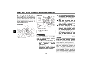
1. Turn signal light bulbZAUM1223
1. License plate light bulb socket
2. License plate light unit
3. ScrewZAUM1190
2
3
U5D7E5E0.book Page 36 Thursday, August 21, 2014 9:30 AM
Page 79 of 98
PERIODIC MAINTENANCE AND ADJUSTMENT
6-37
6 a jack either under each side of the
frame in front of the rear wheel or under
each side of the swingarm.
EAU44792
Front wheel (for non-ABS
models)
WARNING
EWA14841
For the ABS model, have a Yamaha
dealer remove and install the wheel.
EAU56531
To remove the front wheel
WARNING
EWA10822
To avoid injury, securely support the
vehicle so there is no danger of it
falling over.1. Loosen the front wheel axle pinch
bolts, then the wheel axle and the
brake caliper bolts.
2. Lift the front wheel off the ground
according to the procedure in the
previous section “Supporting the
motorcycle”.
1. Axle bolt
2. Front wheel axle pinch bolt A
3. Front wheel axle pinch bolt B
1. Brake caliper bolt
2. Brake caliperZAUM1215
3
ZAUM1192
U5D7E5E0.book Page 37 Thursday, August 21, 2014 9:30 AM
Page 80 of 98

PERIODIC MAINTENANCE AND ADJUSTMENT
6-38
63. Remove the brake caliper by re-
moving the bolts. NOTICE: Do
not apply the brake after the
wheel and brake disc have been
removed, otherwise the brake
pads will be forced shut.
[ECA11073]
4. Pull the wheel axle out, and then
remove the wheel.
To install the front wheel
1. Lift the wheel up between the fork
legs.
2. Insert the wheel axle.
3. Lower the front wheel so that it is
on the ground.
4. Install the brake caliper by install-
ing the bolts.TIPMake sure that there is enough space
between the brake pads before install-
ing the brake caliper onto the brake
disc.5. Tighten the wheel axle to the
specified torque.
6. Tighten the wheel axle pinch bolt
A and pinch bolt B to the specified
torques.7. Retighten the wheel axle pinch
bolt A to the specified torque.
8. Tighten the brake caliper bolts to
the specified torques.
9. Push down hard on the handlebar
several times to check for proper
fork operation.
EAU44802
Rear wheel (for non-ABS
models)
WARNING
EWA14841
For the ABS model, have a Yamaha
dealer remove and install the wheel.
EAU56701
To remove the rear wheel
WARNING
EWA10822
To avoid injury, securely support the
vehicle so there is no danger of it
falling over.1. Loosen the axle nut.
Tightening torques:
Wheel axle:
59 Nm (5.9 m·kgf, 43 ft·lbf)
Front wheel axle pinch bolt:
23 Nm (2.3 m·kgf, 17 ft·lbf)
Brake caliper bolt:
38 Nm (3.8 m·kgf, 27 ft·lbf)
U5D7E5E0.book Page 38 Thursday, August 21, 2014 9:30 AM


WARNING")