Page 20 of 360
FEATURES
1-6
EAS20170
FEATURES
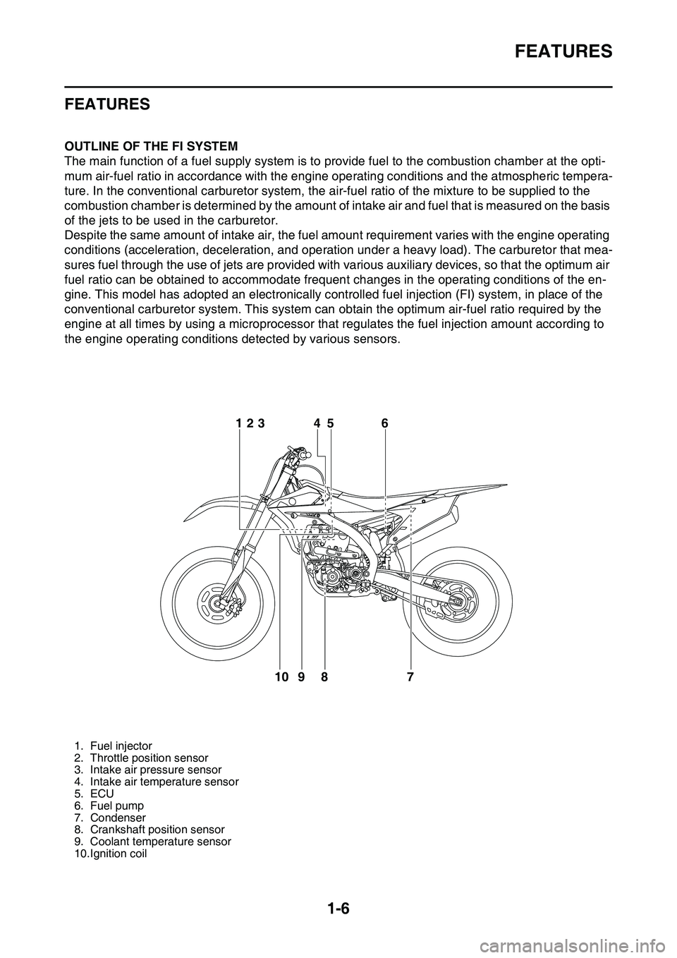
EAS1SL1014OUTLINE OF THE FI SYSTEM
The main function of a fuel supply system is to provide fuel to the combustion chamber at the opti-
mum air-fuel ratio in accordance with the engine operating conditions and the atmospheric tempera-
ture. In the conventional carburetor system, the air-fuel ratio of the mixture to be supplied to the
combustion chamber is determined by the amount of intake air and fuel that is measured on the basis
of the jets to be used in the carburetor.
Despite the same amount of intake air, the fuel amount requirement varies with the engine operating
conditions (acceleration, deceleration, and operation under a heavy load). The carburetor that mea
-
sures fuel through the use of jets are provided with various auxiliary devices, so that the optimum air
fuel ratio can be obtained to accommodate frequent changes in the operating conditions of the en
-
gine. This model has adopted an electronically controlled fuel injection (FI) system, in place of the
conventional carburetor system. This system can obtain the optimum air-fuel ratio required by the
engine at all times by using a microprocessor that regulates the fuel injection amount according to
the engine operating conditions detected by various sensors.
EAS1SL1015
1. Fuel injector
2. Throttle position sensor
3. Intake air pressure sensor
4. Intake air temperature sensor
5. ECU
6. Fuel pump
7. Condenser
8. Crankshaft position sensor
9. Coolant temperature sensor
10.Ignition coil
6
7 8 95 4 123
10
Page 21 of 360
FEATURES
1-7
FI SYSTEM
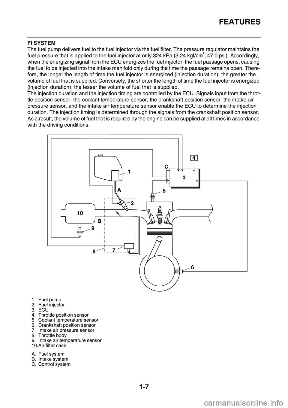
The fuel pump delivers fuel to the fuel injector via the fuel filter. The pressure regulator maintains the
fuel pressure that is applied to the fuel injector at only 324 kPa (3.24 kgf/cm², 47.0 psi). Accordingly,
when the energizing signal from the ECU energizes the fuel injector, the fuel passage opens, causing
the fuel to be injected into the intake manifold only during the time the passage remains open. There
-
fore, the longer the length of time the fuel injector is energized (injection duration), the greater the
volume of fuel that is supplied. Conversely, the shorter the length of time the fuel injector is energized
(injection duration), the lesser the volume of fuel that is supplied.
The injection duration and the injection timing are controlled by the ECU. Signals input from the throt-
tle position sensor, the coolant temperature sensor, the crankshaft position sensor, the intake air
pressure sensor, and the intake air temperature sensor enable the ECU to determine the injection
duration. The injection timing is determined through the signals from the crankshaft position sensor.
As a result, the volume of fuel that is required by the engine can be supplied at all times in accordance
with the driving conditions.
1. Fuel pump
2. Fuel injector
3. ECU
4. Throttle position sensor
5. Coolant temperature sensor
6. Crankshaft position sensor
7. Intake air pressure sensor
8. Throttle body
9. Intake air temperature sensor
10.Air filter case
A. Fuel system
B. Intake system
C. Control system
1
234
5
6 7
8 9 10A
BC
Page 50 of 360
ENGINE SPECIFICATIONS
2-7
Shifting mechanism
Shift mechanism type Shift drum and guide bar
Shift fork guide bar bending limit 0.050 mm (0.0020 in)
Shift fork thickness 4.85 mm (0.1909 in)
Decompression device
Device type Auto decomp
Air filter
Air filter element Wet element
Air filter oil grade Foam air-filter oil
Fuel pump
Pump type Electrical
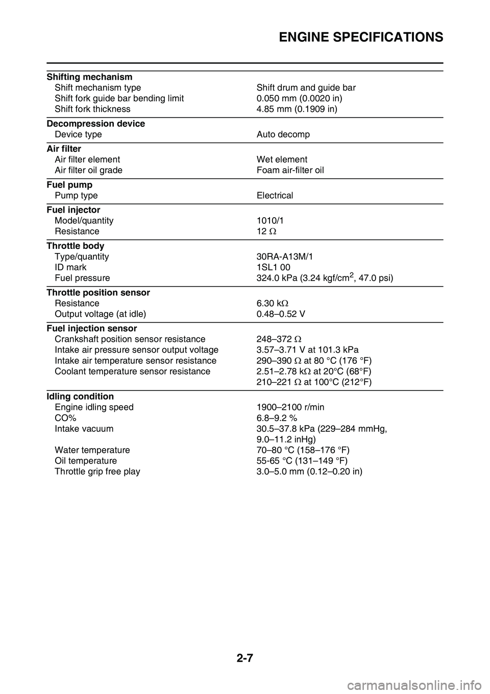
Fuel injector
Model/quantity 1010/1
Resistance 12
Throttle body
Type/quantity 30RA-A13M/1
ID mark 1SL1 00
Fuel pressure 324.0 kPa (3.24 kgf/cm2, 47.0 psi)
Throttle position sensor
Resistance 6.30 k
Output voltage (at idle) 0.48–0.52 V
Fuel injection sensor
Crankshaft position sensor resistance 248–372
Intake air pressure sensor output voltage 3.57–3.71 V at 101.3 kPa
Intake air temperature sensor resistance 290–390 at 80 °C (176 °F)
Coolant temperature sensor resistance 2.51–2.78 k at 20°C (68°F)
210–221 at 100°C (212°F)
Idling condition
Engine idling speed 1900–2100 r/min
CO% 6.8–9.2 %
Intake vacuum 30.5–37.8 kPa (229–284 mmHg,
9.0–11.2 inHg)
Water temperature 70–80 °C (158–176 °F)
Oil temperature 55-65 °C (131–149 °F)
Throttle grip free play 3.0–5.0 mm (0.12–0.20 in)
Page 59 of 360
TIGHTENING TORQUES
2-16
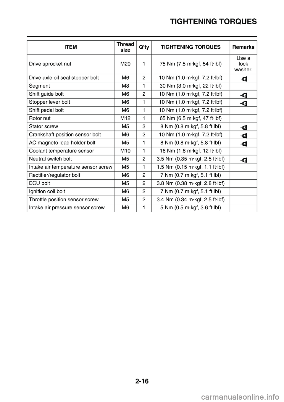
Drive sprocket nutM20175 Nm (7.5 m·kgf, 54 ft·lbf)
Use a
lock
washer.
Drive axle oil seal stopper boltM6210 Nm (1.0 m·kgf, 7.2 ft·lbf)
SegmentM8130 Nm (3.0 m·kgf, 22 ft·lbf)
Shift guide boltM6210 Nm (1.0 m·kgf, 7.2 ft·lbf)
Stopper lever boltM6110 Nm (1.0 m·kgf, 7.2 ft·lbf)
Shift pedal boltM6110 Nm (1.0 m·kgf, 7.2 ft·lbf)
Rotor nutM12165 Nm (6.5 m·kgf, 47 ft·lbf)
Stator screwM538 Nm (0.8 m·kgf, 5.8 ft·lbf)
Crankshaft position sensor boltM6210 Nm (1.0 m·kgf, 7.2 ft·lbf)
AC magneto lead holder boltM518 Nm (0.8 m·kgf, 5.8 ft·lbf)
Coolant temperature sensorM10116 Nm (1.6 m·kgf, 12 ft·lbf)
Neutral switch boltM523.5 Nm (0.35 m·kgf, 2.5 ft·lbf)
Intake air temperature sensor screwM511.5 Nm (0.15 m·kgf, 1.1 ft·lbf)
Rectifier/regulator boltM627 Nm (0.7 m·kgf, 5.1 ft·lbf)
ECU boltM523.8 Nm (0.38 m·kgf, 2.8 ft·lbf)
Ignition coil boltM627 Nm (0.7 m·kgf, 5.1 ft·lbf)
Throttle position sensor screwM523.4 Nm (0.34 m·kgf, 2.5 ft·lbf)
Intake air pressure sensor screwM615 Nm (0.5 m·kgf, 3.6 ft·lbf)
ITEMThread
sizeQ’ty TIGHTENING TORQUES Remarks
LT
LT
LT
LT
LT
LT
LT
Page 79 of 360
CABLE ROUTING DIAGRAM
2-36
1. Bracket
2. Condenser3. Coolant temperature sensor
4. Coupler cover
5. Intake air temperature sensor coupler6. Intake air temperature sensor coupler
7. Radiator hoses
8. Radiator breather hose9. Joint coupler
10. Plate
11. Tension arm12. Throttle position sensor lead
13. Ground lead
14. Throttle position sensor coupler15. Radiator breather hose
16. Cylinder head breather hose
17. Engine guard18. Crankcase
19. Fuel pump coupler
20. Fuel hose21. Condenser lead
22. Fuel pump lead
23. Condenser coupler24. Ground lead terminal
25. Fuel tank
26. Damper27. Rear frame
28. Main harness
A. Insert the condenser into the bracket as far as it
will go.
B. Attach the coupler cover to the coolant tempera-ture sensor coupler.
C. Pass the radiator breather hose to the inside of
the radiator hose (the side of the vehicle).
D. Insert and fix the joint coupler to the plate. After
fixing it, attach the cover.
E. Pass the throttle position sensor lead to the out-side of the tension arm (the outside of the vehi-cle).
F. After connecting the throttle position sensor cou-pler, attach the cover.
G. Pass the radiator breather hose to the outside of
the tension arm and the throttle position sensor
lead (the outside of the vehicle), and to the inside
of the radiator hose (the side of the vehicle).
H. Pass the protector of the cylinder head breather
hose until it touches the holder.
I. Pass the cylinder head breather hose between
the engine guard and the crankcase.
J. Install the end of the cylinder head breather hose
with it facing downward.
K. After connecting the fuel pump coupler, attach
the coupler cover.
L. 55 mm (2.17 in) (seat load receiver)
M. Clamp the fuel hose and the fuel pump lead by
the holder. Make sure that the painted part on the
fuel hose is clamped, and face the lock on the
clamp toward the rear top of the vehicle.
N. Do not install the plastic locking tie to the seat
load receiver.
O. Make the lock on the plastic locking tie face the
front of the vehicle, and make the end face the
bottom of the vehicle. Do not cut the end.
P. Install the ground lead terminal between the plate
and the bolt.
Q. DetentR. Fix the ground lead terminal to the detent in the
plate. For the ground lead terminal, either side
will do.
S. Insert the projection on the plastic locking tie into
the hole in the rear frame.
T. Clamp the painted part on the fuel hose by the
plastic clamp. Make the lock on the plastic clamp
face the bottom of the vehicle, and cut the end.
Page 198 of 360
ENGINE REMOVAL
5-3
Removing the electronic parts
OrderPart nameQ’tyRemarks
Use a suitable stand to raise the front wheel
off the ground.
SeatRefer to “GENERAL CHASSIS” on page 4-1.
Side cover (left/right)Refer to “GENERAL CHASSIS” on page 4-1.
Air scoop (left / right)Refer to “GENERAL CHASSIS” on page 4-1.
Fuel tankRefer to “FUEL TANK” on page 7-1.
Air filter case cover
1Rectifier/regulator1
2ECU1
3Ignition coil1
4Condenser1
5Neutral switch1
6AC magneto lead1Disconnect.
7Crankshaft position sensor coupler1Disconnect.
8Coolant temperature sensor coupler1Disconnect.
For installation, reverse the removal proce-dure.
T.R.
T.R.
T.R.T.R.
8 3
7
6
154
2
LT
Page 214 of 360
CYLINDER HEAD
5-19
EAS1SL1214
CYLINDER HEAD
Removing the cylinder head
OrderPart nameQ’tyRemarks
SeatRefer to “GENERAL CHASSIS” on page 4-1.
Side cover (left/right)Refer to “GENERAL CHASSIS” on page 4-1.
Air scoop (left / right)Refer to “GENERAL CHASSIS” on page 4-1.
Fuel tankRefer to “FUEL TANK” on page 7-1.
Exhaust pipe and silencerRefer to “ENGINE REMOVAL” on page 5-1.
Radiator hoseDisconnect.
Coolant temperature sensor couplerDisconnect.
Throttle bodyRefer to “THROTTLE BODY” on page 7-5.
CamshaftRefer to “CAMSHAFT” on page 5-11.
Upper engine bracketRefer to “ENGINE REMOVAL” on page 5-1
1Bolt (cylinder head)2
2Bolt (cylinder head)4
3Cylinder head1
4Cylinder head gasket1
5Timing chain guide (intake side)1
6Oil check bolt2
7 66
1st
2nd
Final20 Nm (2.0 m
kgf, 14 ftIbf)T.
R.
30 Nm (3.0 mkgf, 22 ftIbf)
10 Nm (1.0 mkgf, 7.2 ftIbf)T.R.
10 Nm (1.0 mkgf, 7.2 ftIbf)T.R.
15 Nm (1.5 mkgf, 11 ftIbf)T.
R
.
Page 273 of 360
RADIATOR
6-2
4Radiator hose 21
5Radiator hose 31
6Radiator hose 41
7Radiator pipe 21
8Radiator breather hose1
9Left radiator1
10Radiator hose 11
11Radiator pipe 11
12Coolant temperature sensor1
For installation, reverse the removal proce-dure.
Removing the radiator
Order Part name Q’ty Remarks
11
12
New
New
New
LS
LS