Page 102 of 230
5-1
RADIATOR
ENGINE
This section is intended for those who have basic knowledge and skill concerning the servicing of Yamaha motorcycles
(e.g., Yamaha dealers, service engineers, etc.) Those who have little knowledge and skill concerning servicing are request-
ed not to undertake inspection, adjustment, disassembly, or reassembly only by reference to this manual. It may lead to
servicing trouble and mechanical damage.
RADIATOR
REMOVING THE RADIATOR
Order Part name Q'ty Remarks
Drain the coolant.Refer to "CHECKING THE COOLANT" sec-
tion in the CHAPTER 3.
Seat, fuel tank and left side coverRefer to "REMOVING THE SEAT, FUEL
TANK AND SIDE COVERS" section in the
CHAPTER 3.
1 Radiator guard 2
2 Radiator hose clamp 10 Only loosening.
3 Radiator hose 1 1
4 Left radiator 1
5 Radiator hose 3 1
6 Radiator pipe 2 1
7 Radiator hose 5 1
Page 105 of 230
5-4
CARBURETOR
CARBURETOR
REMOVING THE CARBURETOR
Order Part name Q'ty Remarks
Seat and fuel tank Refer to "REMOVING THE SEAT, FUEL
TANK AND SIDE COVERS" section in the
CHAPTER 3.
Rear shock absorber Refer to "REAR SHOCK ABSORBER" sec-
tion in the CHAPTER 6.
1Clamp 2
2 Throttle position sensor lead coupler 1
3 Throttle cable cover 1
4 Throttle cable 2
5 Clamp (air filter joint) 1 Loosen the screw (air filter joint).
6 Clamp (carburetor joint) 1 Loosen the screws (carburetor joint).
7 Hot starter plunger 1
8 Carburetor assembly 1
9 Carburetor joint 1
4 Nm (0.4 m kg, 2.9 ft lb)
2 Nm (0.2 m kg, 1.4 ft lb)
11 Nm (1.1 m kg, 8.0 ft lb)
4 Nm (0.4 m kg, 2.9 ft lb)
10 Nm (1.0 m kg, 7.2 ft lb)
3 Nm (0.3 m kg, 2.2 ft lb)
3 Nm (0.3 m kg, 2.2 ft lb)
Page 108 of 230
5-7
CARBURETOR
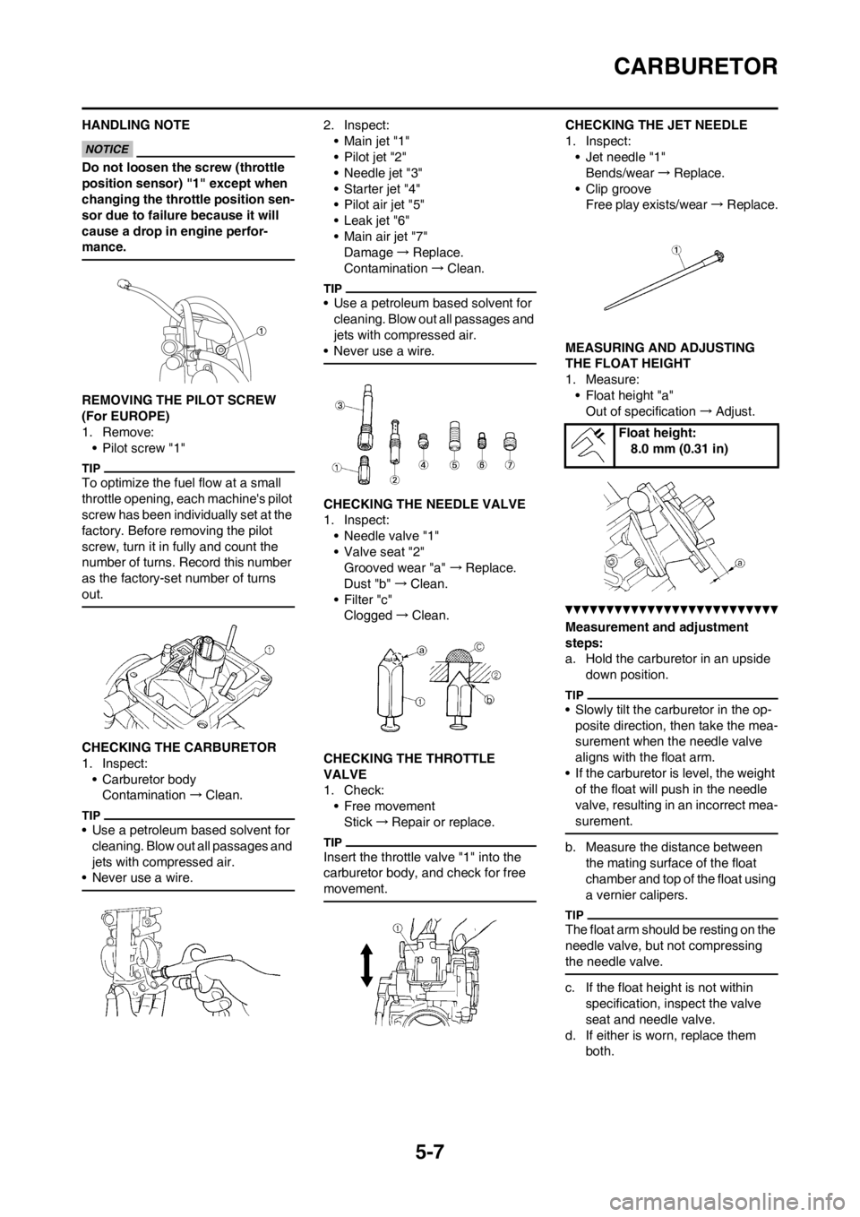
HANDLING NOTE
Do not loosen the screw (throttle
position sensor) "1" except when
changing the throttle position sen-
sor due to failure because it will
cause a drop in engine perfor-
mance.
REMOVING THE PILOT SCREW
(For EUROPE)
1. Remove:
• Pilot screw "1"
To optimize the fuel flow at a small
throttle opening, each machine's pilot
screw has been individually set at the
factory. Before removing the pilot
screw, turn it in fully and count the
number of turns. Record this number
as the factory-set number of turns
out.
CHECKING THE CARBURETOR
1. Inspect:
• Carburetor body
Contamination→Clean.
• Use a petroleum based solvent for
cleaning. Blow out all passages and
jets with compressed air.
• Never use a wire.
2. Inspect:
•Main jet "1"
• Pilot jet "2"
• Needle jet "3"
• Starter jet "4"
•Pilot air jet "5"
• Leak jet "6"
• Main air jet "7"
Damage→Replace.
Contamination→Clean.
• Use a petroleum based solvent for
cleaning. Blow out all passages and
jets with compressed air.
• Never use a wire.
CHECKING THE NEEDLE VALVE
1. Inspect:
• Needle valve "1"
• Valve seat "2"
Grooved wear "a" →Replace.
Dust "b" →Clean.
• Filter "c"
Clogged→Clean.
CHECKING THE THROTTLE
VALVE
1. Check:
• Free movement
Stick→Repair or replace.
Insert the throttle valve "1" into the
carburetor body, and check for free
movement.
CHECKING THE JET NEEDLE
1. Inspect:
• Jet needle "1"
Bends/wear→Replace.
• Clip groove
Free play exists/wear→Replace.
MEASURING AND ADJUSTING
THE FLOAT HEIGHT
1. Measure:
• Float height "a"
Out of specification→Adjust.
Measurement and adjustment
steps:
a. Hold the carburetor in an upside
down position.
• Slowly tilt the carburetor in the op-
posite direction, then take the mea-
surement when the needle valve
aligns with the float arm.
• If the carburetor is level, the weight
of the float will push in the needle
valve, resulting in an incorrect mea-
surement.
b. Measure the distance between
the mating surface of the float
chamber and top of the float using
a vernier calipers.
The float arm should be resting on the
needle valve, but not compressing
the needle valve.
c. If the float height is not within
specification, inspect the valve
seat and needle valve.
d. If either is worn, replace them
both.
Float height:
8.0 mm (0.31 in)
Page 115 of 230
5-14
CAMSHAFTS
CAMSHAFTS
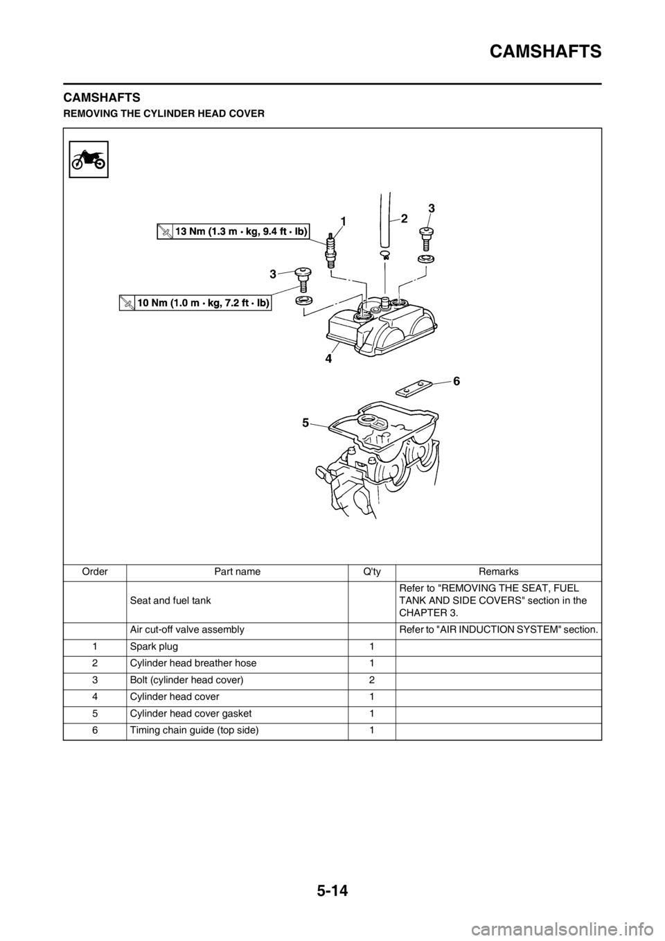
REMOVING THE CYLINDER HEAD COVER
Order Part name Q'ty Remarks
Seat and fuel tank Refer to "REMOVING THE SEAT, FUEL
TANK AND SIDE COVERS" section in the
CHAPTER 3.
Air cut-off valve assembly Refer to "AIR INDUCTION SYSTEM" section.
1 Spark plug 1
2 Cylinder head breather hose 1
3 Bolt (cylinder head cover) 2
4 Cylinder head cover 1
5 Cylinder head cover gasket 1
6 Timing chain guide (top side) 1
Page 120 of 230
5-19
CYLINDER HEAD
CYLINDER HEAD
REMOVING THE CYLINDER HEAD
Order Part name Q'ty Remarks
Seat and fuel tank Refer to "REMOVING THE SEAT, FUEL
TANK AND SIDE COVERS" section in the
CHAPTER 3.
Exhaust pipe and silencerRefer to "REMOVING THE EXHAUST PIPE
AND SILENCER" section in the CHAPTER 3.
Radiator hose 1 Disconnect at cylinder head side.
Carburetor Refer to "CARBURETOR" section.
Air cut-off valve assembly Refer to "AIR INDUCTION SYSTEM" section.
Camshaft Refer to "CAMSHAFTS" section.
Upper engine bracket Refer to "ENGINE REMOVAL" section.
1 Radiator pipe 1
2 Oil delivery pipe 1
3Nut 2
4 Bolt [L = 135 mm (5.31 in)] 2
5 Bolt [L = 145 mm (5.71 in)] 2
6 Cylinder head 1
7 Timing chain guide (exhaust side) 1
Page 150 of 230
5-49
AC MAGNETO AND STARTER CLUTCH
AC MAGNETO AND STARTER CLUTCH
REMOVING THE AC MAGNETO AND STARTER CLUTCH
Order Part name Q'ty Remarks
Drain the engine oil.Refer to "CHANGING THE ENGINE OIL"
section in the CHAPTER 3.
Seat and fuel tankRefer to "REMOVING THE SEAT, FUEL
TANK AND SIDE COVERS" section in the
CHAPTER 3.
Disconnect the AC magneto lead.
1 Shift pedal 1
2 Cover (torque limiter) 1
3 Torque limiter 1 Do not disassemble.
4 Crankcase cover (left) 1
5 Gasket 1
6 Dowel pin 2
7* Nut (rotor) 1 Refer to TIP.
8 Rotor 1 Refer to removal section.
9 Woodruff key 1
10 Starter clutch drive gear 1
11 Starter clutch assembly cover 1
Page 155 of 230
5-54
ENGINE REMOVAL
ENGINE REMOVAL
REMOVING THE ENGINE
Order Part name Q'ty Remarks
Hold the machine by placing the suitable stand
under the frame.Refer to "HANDLING NOTE".
Drain the engine oil.Refer to "CHANGING THE ENGINE OIL"
section in the CHAPTER 3.
Seat and fuel tank Refer to "REMOVING THE SEAT, FUEL
TANK AND SIDE COVERS" section in the
CHAPTER 3.
Carburetor Refer to "CARBURETOR" section.
Exhaust pipe and silencer Refer to "REMOVING THE EXHAUST PIPE
AND SILENCER" section in the CHAPTER 3.
Air cut-off valve assembly Refer to "AIR INDUCTION SYSTEM" section.
Clutch cable Disconnect at the engine side.
Radiator Refer to "RADIATOR" section.
Shift pedalRefer to "AC MAGNETO AND STARTER
CLUTCH" section.
Cylinder head breather hose Refer to "CAMSHAFTS" section.
Oil hose and oil tank breather hose Refer to "OIL PUMP" section.
Ignition coil
Page 203 of 230
6-36
REAR SHOCK ABSORBER
REAR SHOCK ABSORBER
REMOVING THE REAR SHOCK ABSORBER
Order Part name Q'ty Remarks
Hold the machine by placing the suitable stand
under the engine.Refer to "HANDLING NOTE".
Seat and side cover Refer to "REMOVING THE SEAT, FUEL
TANK AND SIDE COVERS" section in the
CHAPTER 3.
Silencer Refer to "REMOVING THE EXHAUST PIPE
AND SILENCER" section in the CHAPTER 3.
Drain the coolant.Refer to "CHANGING THE COOLANT" sec-
tion in the CHAPTER 3.
Catch tank breather hose Disconnect at the catch tank side.
Catch tank hose Disconnect at the catch tank side.
Air induction hose (air cut-off valve-air filter case) Disconnect at the air filter case side.
Cylinder head breather hose Disconnect at the air filter case side.
BatteryRefer to "CHECKING AND CHARGING THE
BATTERY" section in the CHAPTER 3.
Disconnect the starter relay coupler.
Starter motor lead Disconnect at the starter relay side.
1 Locking tie 4