Page 81 of 110

PERIODIC MAINTENANCE AND ADJUSTMENT
6-31
6
EAU23292
Checking the wheel bearin gsThe front and rear wheel bearings must
be checked at the intervals specified in
the periodic maintenance and lubrica-
tion chart. If there is play in the wheel
hub or if the wheel does not turn
smoothly, have a Yamaha dealer
check the wheel bearings.
EAU50211
BatteryThe battery is located under the rider
seat. (See page 3-18.)
This model is equipped with a VRLA
(Valve Regulated Lead Acid) battery.
There is no need to check the electro-
lyte or to add distilled water. However,
the battery lead connections need to
be checked and, if necessary, tight-
ened.
WARNING
EWA10761
Electrolyte is poisonous an d
d an gerous since it contains sul-
furic aci d, which causes severe b
urns. Avoi d any contact with
skin, eyes or clothin g an d al-
ways shiel d your eyes when
workin g near b atteries. In case
of contact, ad minister the fol-
lowin g FIRST AID.
EXTERNAL: Flush with plenty of water.
INTERNAL: Drink lar ge quan-
tities of water or milk an d im-
me diately call a physician.
EYES: Flush with water for 15 minutes an d seek prompt
me dical attention.
Batteries pro duce explosive hy-
d ro gen gas. Therefore, keep
sparks, flames, ci garettes, etc.,
away from the battery an d pro-
vi de sufficient ventilation when
char gin g it in an enclose d
space.
KEEP THIS AND ALL BATTER-
IES OUT OF THE REACH OF
CHILDREN.
To char ge the b attery
Have a Yamaha dealer charge the bat-
tery as soon as possible if it seems to
have discharged. Keep in mind that the
1. Battery
2. Positive battery lead (red)
3. Negative battery lead (black)
1
2
3
U2SHE1E0.book Page 31 Tuesday, July 15, 2014 4:04 PM
Page 82 of 110

PERIODIC MAINTENANCE AND ADJUSTMENT
6-32
6battery tends to discharge more quick-
ly if the vehicle is equipped with op-
tional electrical accessories.
NOTICE
ECA16522
To char
ge a VRLA (Valve Re gulate d
Lea d Aci d) battery, a special (con-
stant-voltag e) battery char ger is re-
quired . Using a conventional b attery
char ger will damag e the b attery.To store the b attery
1. If the vehicle will not be used for more than one month, remove the
battery, fully charge it, and then
place it in a cool, dry place.
NOTICE: When removin g the
b attery, be sure the key is
turne d to “OFF”, then d iscon-
nect the neg ative lead b efore
d isconnectin g the positive lea d.
[ECA16303]
2. If the battery will be stored for
more than two months, check it at
least once a month and fully
charge it if necessary.
3. Fully charge the battery before in- stallation. NOTICE: When install-
in g the b attery, be sure the key is turned
to “OFF”, then connect
the positive lead before con-
nectin g the ne gative lea d.
[ECA16841]
4. After installation, make sure that
the battery leads are properly con-
nected to the battery terminals.NOTICE
ECA16531
Always keep the b attery charged .
Storin g a d ischar ged battery can
cause permanent battery damag e.
EAU49825
Replacin g the fusesThe main fuse, the fuel injection sys-
tem fuse, and the fuse boxes, which
contain the fuses for the individual cir-
cuits, are located under the rider seat.
(See page 3-18.)
FZ8-N1. Main fuse
2. Fuse box
3. Fuel injection system fuse
4. Fuel injection system spare fuse
1
2
3
4
U2SHE1E0.book Page 32 Tuesday, July 15, 2014 4:04 PM
Page 83 of 110
PERIODIC MAINTENANCE AND ADJUSTMENT
6-33
6
FZ8-NA FZ8-N FZ8-NA
1. Fuse box
2. Fuel injection system fuse
3. Fuel injection system spare fuse
4. Main fuse
4
1
2
3
1. Ignition fuse
2. Signaling system fuse
3. Taillight fuse
4. Backup fuse (for clock and immobilizer sys-
tem)
5. Right radiator fan motor fuse
6. Left radiator fan motor fuse
7. Headlight fuse
8. Spare fuse
18
7
2
3
4
5
6
1. Ignition fuse
2. Signaling system fuse
3. Headlight fuse
4. Backup fuse (for clock and immobilizer sys- tem)
5. ABS solenoid fuse
6. ABS motor fuse
7. Spare fuse
8. ABS control unit fuse
9. Right radiator fan motor fuse
1
8
92
3
4
5
6
7
7
U2SHE1E0.book Page 33 Tuesday, July 15, 2014 4:04 PM
Page 84 of 110

PERIODIC MAINTENANCE AND ADJUSTMENT
6-34
6FZ8-NA
TIPTo access the fuel injection system
fuse, remove the starter relay cover by
pulling it upward.
If a fuse is blown, replace it as follows.
1. Turn the key to “OFF” and turn off the electrical circuit in question.
2. Remove the blown fuse, and then install a new fuse of the specified
amperage. WARNING! Do not
use a fuse of a hi gher ampera ge
ratin g than recommen ded to
avoi d causin g extensive d am-
a g e to the electrical system an d
possi bly a fire.
[EWA15132]
3. Turn the key to “ON” and turn on
the electrical circuit in question to
check if the device operates.
4. If the fuse immediately blows again, have a Yamaha dealer
check the electrical system.
1. Left radiator fan motor fuse
2. Taillight fuse
3. Spare fuse
1
2
3
1. Starter relay cover
2. Fuel injection system fuse
3. Fuel injection system spare fuse
1
23
Specifie d fuses:
Main fuse:
50.0 A
Headlight fuse:
15.0 A
Taillight fuse: 10.0 A
Signaling system fuse: 10.0 A
Ignition fuse:
15.0 A
Radiator fan motor fuse: 10.0 A × 2
ABS motor fuse: FZ8-NA 30.0 A
ABS solenoid fuse:
FZ8-NA 20.0 A
Fuel injection system fuse: 15.0 A
ABS control unit fuse: FZ8-NA 7.5 A
Backup fuse:
10.0 A
U2SHE1E0.book Page 34 Tuesday, July 15, 2014 4:04 PM
Page 85 of 110

PERIODIC MAINTENANCE AND ADJUSTMENT
6-35
6
EAU49654
Replacing the hea dlig ht bul bThis model is equipped with a halogen
bulb headlight. If the headlight bulb
burns out, replace it as follows.NOTICE
ECA10651
Take care not to damag e the follow-
in g parts:
Hea dlig ht bul b
Do not touch the glass part of
the hea dlig ht bul b to keep it free
from oil, otherwise the transpar-
ency of the g lass, the luminosity
of the b ulb, an d the b ulb life will
b e ad versely affected . Thor-
ou ghly clean off any d irt and fin-
g erprints on the head light bul b
using a cloth moistened with al-
cohol or thinner.
Hea dlig ht lens
Do not affix any type of tinted
film or stickers to the head light
lens.
Do not use a hea dlig ht bul b of a
watta ge hi gher than specified .
1. Remove the headlight unit top
cover by removing its bolts.
2. Remove the bolt behind the head- light unit as shown. 3. Remove the headlight unit bolts.
4. Disconnect the coupler, then take
off the headlight unit from the ve-
hicle.1. Do not touch the glass part of the bulb.
1. Headlight unit top cover
2. Bolt
2
1
1. Bolt
1. Bolt
1
1
U2SHE1E0.book Page 35 Tuesday, July 15, 2014 4:04 PM
Page 86 of 110
PERIODIC MAINTENANCE AND ADJUSTMENT
6-36
65. Disconnect the headlight coupler,
then remove the headlight bulb
cover.
6. Unhook the headlight bulb holder, then remove the burnt-out bulb. 7. Place a new headlight bulb into
position, then secure it with the
bulb holder.
8. Install the headlight bulb cover, then connect the headlight cou-
pler.
9. Connect the coupler, then insert the projection on the headlight
unit into the grommet on the vehi-
cle to fit the headlight unit in its
original position. 10. Install the headlight unit bolts.
11. Install the bolt behind the head-
light unit.
12. Place the top cover in its original position, and then install its bolts.
1. Coupler
1. Headlight coupler
2. Headlight bulb cover
1
1
2
1. Headlight bulb holder
2. Headlight bulb
1
2
1. Projection
2. Grommet
2
1
U2SHE1E0.book Page 36 Tuesday, July 15, 2014 4:04 PM
Page 87 of 110
PERIODIC MAINTENANCE AND ADJUSTMENT
6-37
6
13. Have a Yamaha dealer adjust the
headlight beam if necessary.
EAU50771
Replacin g the auxiliary li ght
b ul bIf the auxiliary light bulb burns out, re-
place it as follows.
1. Remove the headlight unit. (See page 6-35.)
2. Remove the auxiliary light coupler (together with the socket and
bulb) by turning the coupler coun-
terclockwise.
3. Remove the burnt-out bulb by pulling it out. 4. Insert a new bulb into the socket.
5. Install the coupler (together with
the socket and bulb) by turning it
clockwise.
6. Install the headlight unit.1. Auxiliary light coupler
1
1. Auxiliary light bulb
2. Auxiliary light bulb socket
3. Auxiliary light coupler
1
2
3
U2SHE1E0.book Page 37 Tuesday, July 15, 2014 4:04 PM
Page 88 of 110

2. Remove the tail/brake light bulb socket (together with the")
PERIODIC MAINTENANCE AND ADJUSTMENT
6-38
6
EAU24116
Replacing the tail/ brake li ght
b ul b1. Remove the passenger seat. (See
page 3-18.)
2. Remove the tail/brake light bulb socket (together with the bulb) by
turning it counterclockwise.
3. Remove the burnt-out bulb by pushing it in and turning it coun-
terclockwise.
4. Insert a new bulb into the socket, push it in, and then turn it clock-
wise until it stops.
5. Install the socket (together with the bulb) by turning it clockwise.
6. Install the passenger seat.
EAU24205
Replacin g a turn si gnal li ght
b ul b1. Remove the turn signal light lens
by removing the screw.
2. Remove the burnt-out bulb by pushing it in and turning it coun-
terclockwise. 3. Insert a new bulb into the socket,
push it in, and then turn it clock-
wise until it stops.
4. Install the lens by installing the screw. NOTICE: Do not over-
ti g hten the screw, otherwise the
lens may break.
[ECA11192]
1. Tail/brake light bulb socket
1
1. Turn signal light lens
2. Screw
1
2
1. Turn signal light bulb
1
U2SHE1E0.book Page 38 Tuesday, July 15, 2014 4:04 PM
 1
1 2
2 3
3 4
4 5
5 6
6 7
7 8
8 9
9 10
10 11
11 12
12 13
13 14
14 15
15 16
16 17
17 18
18 19
19 20
20 21
21 22
22 23
23 24
24 25
25 26
26 27
27 28
28 29
29 30
30 31
31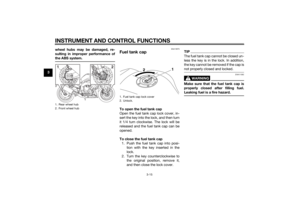 32
32 33
33 34
34 35
35 36
36 37
37 38
38 39
39 40
40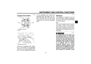 41
41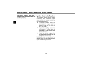 42
42 43
43 44
44 45
45 46
46 47
47 48
48 49
49 50
50 51
51 52
52 53
53 54
54 55
55 56
56 57
57 58
58 59
59 60
60 61
61 62
62 63
63 64
64 65
65 66
66 67
67 68
68 69
69 70
70 71
71 72
72 73
73 74
74 75
75 76
76 77
77 78
78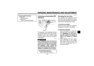 79
79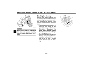 80
80 81
81 82
82 83
83 84
84 85
85 86
86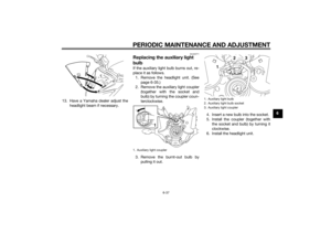 87
87 88
88 89
89 90
90 91
91 92
92 93
93 94
94 95
95 96
96 97
97 98
98 99
99 100
100 101
101 102
102 103
103 104
104 105
105 106
106 107
107 108
108 109
109

