2014 VOLVO S80 parking brake
[x] Cancel search: parking brakePage 180 of 380

04 Driver support
Park assist*
04
178* Option/accessory, for more information, see Introduction.
NOTE
• Rear park assist is deactivated auto- matically when towing a trailer if Volvogenuine trailer wiring is used. If a non-Volvo trailer hitch is being used, it maybe necessary to switch off the systemmanually, see page 176.
• The system will not detect highobjects, such as a loading dock, etc.
• Objects such as chains, thin shinypoles or low objects may temporarilynot be detected by the system. Thismay result in the pulsing tone unex-pectedly stopping instead of changingto a constant tone as the vehicleapproaches the object. In such cases,use caution when backing up or stopthe vehicle to help avoid damage.
Front park assist
G021424
The distance monitored in front of the vehicle is approximately 2.5 ft (0.8 m). The audiblesignal comes from the audio system's frontspeakers. It may not be possible to combine auxiliary headlights and front park assist since theselights could trigger the system's sensors.
NOTE
Front park assist is deactivated when the parking brake is applied and or when thegear selector is in the
P position.
Faults in the system
If the information symbol illuminates andPark assist syst Service required is shown
on the information display, this indicates that the system is not functioning properly andhas been disengaged. Consult a trained andqualified Volvo service technician.
CAUTION
In certain circumstances, the park assist system may give unexpected warning sig-nals that can be caused by external soundsources that use the same ultrasound fre-quencies as the system. This may includesuch things as the horns of other vehicles,wet tires on asphalt, pneumatic brakes,motorcycle exhaust pipes, etc. This doesnot indicate a fault in the system.
Page 265 of 380

06 Infotainment
Cell phone voice control*
06
* Option/accessory, for more information, see Introduction.263
Getting started
Voice control button (1) on the steering wheel.
Activating the systemBefore any phone voice commands can be used, a Bluetooth ®
-enabled cell phone must
be paired with the infotainment system. If a phone command is given, the system willinform you If there is no cell phone paired.See page 254 for information on pairing a cellphone. Press the voice control button (1 in the illus- tration) to activate the system and initiate acommand dialogue. The system will displaycommonly used commands on the screenwhen the button has been pressed. While using the voice control system, keep the following points in mind: •
When giving commands, speak at your usual speed and in a normal tone of voiceafter the tone
• The vehicle's doors, windows and moon-roof should be closed when using thevoice control system
• Avoid background noises in the cabinwhen using the system
NOTE
If you are uncertain of the commands that you can use, saying "help" will prompt thesystem to provide a number of commandsthat can be used in a specific situation. Voice control commands can be cancelled by:
• Saying "cancel"
• Not speaking
• Pressing and holding the voice control button
• Pressing
EXIT or one of the mode but-
tons ( RADIO , MEDIA , etc.).
Voice control support feature
•Tutorial
: A feature that helps acquaint
you with the system and the procedure for giving commands. This feature can be accessed by pressing the MY CAR
button in the center console and
turning TUNE.
TutorialThe tutorial feature can be started in two ways:
NOTE
The tutorial feature can only be started when the vehicle is parked and the parkingbrake is applied.
•By pressing the voice control button and saying "Voice tutorial."
• By pressing
MY CAR and going to
SettingsVoice settingsVoice
tutorial. Press OK/MENU to begin the
tutorial lesson.
The tutorial is divided into three lessons, which take a total of approximately 5 minutesto complete. By default, the system will begin with the first lesson. To skip to the next lesson, press thevoice control button and say "next." Go backto a previous lesson by saying "previous." Press and hold the voice control button to exit the tutorial.
Page 278 of 380

07 During your trip
Loading
07
276* Option/accessory, for more information, see Introduction.
Introduction
The load carrying capacity of your vehicle is determined by factors such as the number ofpassengers, the amount of cargo, the weightof any accessories that may be installed, etc. To increase loading space, the rear seat backrests can be folded down, see page 89. When loading the trunk, keep the following in mind:
The trunk lid can be unlocked anpopped open slightly via the buttonlocated on the lighting panel, see
page 68.
• Load objects in the trunk against the backrest whenever possible.
• Unstable loads can be secured to theload anchoring eyelets with straps or weblashings to help keep them from shifting.
• Stop the engine and apply the parkingbrake when loading or unloading longobjects. The gear selector can beknocked out of position by long loads,which could set the vehicle in motion.
WARNING
• Stop the engine, put the gear selector in
P, and apply the parking brake
when loading or unloading longobjects.
• The vehicle's driving characteristicsmay change depending on the weightand distribution of the load.
• A 44-pound (20 kg) object produces aforce of 2,200 pounds (1,000 kg) in ahead-on collision at 30 mph (50 km/h).
• The rear seat should not be loaded toa level higher than 2 in. (5 cm) belowthe upper edge of the rear side win-dows. Objects placed higher than thislevel could impede the function of theVolvo Inflatable Curtain.
Folding down the rear seat backrests
The rear seat backrests can be folded down for additional loading space, see page 90.
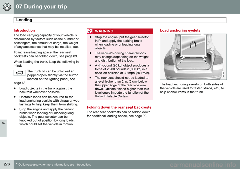
Load anchoring eyelets
G021462
The load anchoring eyelets on both sides of the vehicle are used to fasten straps, etc., tohelp anchor items in the trunk.
Page 282 of 380

07 During your trip
Towing a trailer
07
280
NOTE
•When parking the vehicle with a trailer on a hill, apply the parking brakebefore putting the gear selector in
P.
Always follow the trailer manufactur-er's recommendations for wheelchocking.
• When starting on a hill, put the gearselector in
D before releasing the park-
ing brake. See also page 131 for moredetailed information about starting offon a hill while towing a trailer.
• If you use the manual (Geartronic) shiftpositions while towing a trailer, makesure the gear you select does not puttoo much strain on the engine (usingtoo high a gear).
• The drawbar assembly/trailer hitchmay be rated for trailers heavier thanthe vehicle is designed to tow. Pleaseadhere to Volvo's recommended trailerweights.
• Avoid driving with a trailer on inclinesof more than 15%.
Trailer cableAn adapter is required if the vehicle's trailer hitch has a 13-pin connector and the trailerhas 7 pins. Use an adapter cable approved by Volvo. Make sure the cable does not dragon the ground.
Trailer Stability Assist (TSA)
Trailer Stability Assist is a system designed to help stabilize a vehicle that is towing a trailerwhen the vehicle and trailer have begun tosway and is part of the Dynamic Stability andTraction Control system (DSTC). See page136 for information on DSTC.
FunctionA vehicle towing a trailer may begin to swayfor various reasons. Normally this only occursat high speeds but, for example, if the traileris overloaded or if the load is unevenly dis-tributed in the trailer, there is risk of swayingat speeds between approximately 45-55 mph(70-90 km/h). Swaying may be caused by factors such as: •
The vehicle and trailer are hit by a sud- den, strong crosswind
• The vehicle and trailer are traveling on anuneven road surface or drive over a bump
• Sudden movements of the steering wheel
Facts about TSA
•
TSA intervenes at speeds above approxi-mately 40 mph (60 km/h)
• The DSTC symbol (
) in the instru-
ment panel will flash when TSA is working
• If the driver switches off the DSTC sys- tem's Spin Control function, TSA will alsobe switched off (but will be on again thenext time the engine is started)
• TSA may not intervene when the vehicleand trailer begin to sway if the driver triesto compensate for the swaying motion bymoving the steering wheel rapidly
How TSA worksOnce swaying has begun, it can be very diffi- cult to stop, which makes it difficult to controlthe vehicle and trailer. The TSA system continuously monitors the vehicle's movements, particularly lateralmovement. If the system detects a tendencyto sway, the brakes are applied individuallyon the front wheels, which has a stabilizingeffect on the vehicle and trailer. This is oftenenough to enable the driver to regain controlof the vehicle. If this is not adequate to stop the swaying motion, the brakes are applied to all of thewheels on the vehicle and on the trailer if it isequipped with brakes, and engine power is
Page 285 of 380

07 During your trip
Emergency towing
07
283
Towing the vehicle
1. With the remote key fully pressed into theignition slot 1
, press START/STOP
ENGINE for approximately 2 seconds to
activate ignition mode II.
2. The remote key must remain in the igni- tion slot 2
for the entire time that the vehi-
cle is being towed.
3. Keep the tow rope taut when the towing vehicle slows down by applying light pressure on the brake pedal. This willhelp prevent jarring movements of thevehicle being towed.
4. Be prepared to apply the brakes to stop the vehicle being towed.CAUTION
General towing precautions:
• Please check with state and local authorities before attempting this typeof towing, as vehicles being towed aresubject to regulations regarding maxi-mum towing speed, length and type oftowing device, lighting, etc.
• If the vehicle's battery is dead, attachjumper cables (see page 119) to pro-vide current for releasing the electricparking brake and to move the gearselector from the
P position to N. If
this is not possible, see page 124 forinformation about manually overridingthe shiftlock system to move the gearselector from P to N.
• Maximum speed: 50 mph (80 km/h).Do not exceed the maximum allowabletowing speed.
• Maximum distance with front wheelson ground: 50 miles (80 km).
• The vehicle should only be towed inthe forward direction.
Having the vehicle towed by a tow truck
Call for professional help from an authorized towing company.Volvo recommends the useof flat bed equipment. The towing eyelet may be used to pull the vehicle onto a flatbed tow truck if:
• The angle of the tow truck’s ramp is not more than 12 degrees from a horizontalplane
• The vehicle’s wheels rotate freely and rollstraight ahead
WARNING
No person or object should be behind the tow truck while the vehicle is being pulledup onto the flatbed.
1
Not necessary in vehicles with the optional keyless drive.
2 For vehicles with the the optional keyless dirive, the remote key must be in the vehicle.
Page 306 of 380

08 Wheels and tires
Tire Sealing System*
08
304* Option/accessory, for more information, see Introduction.
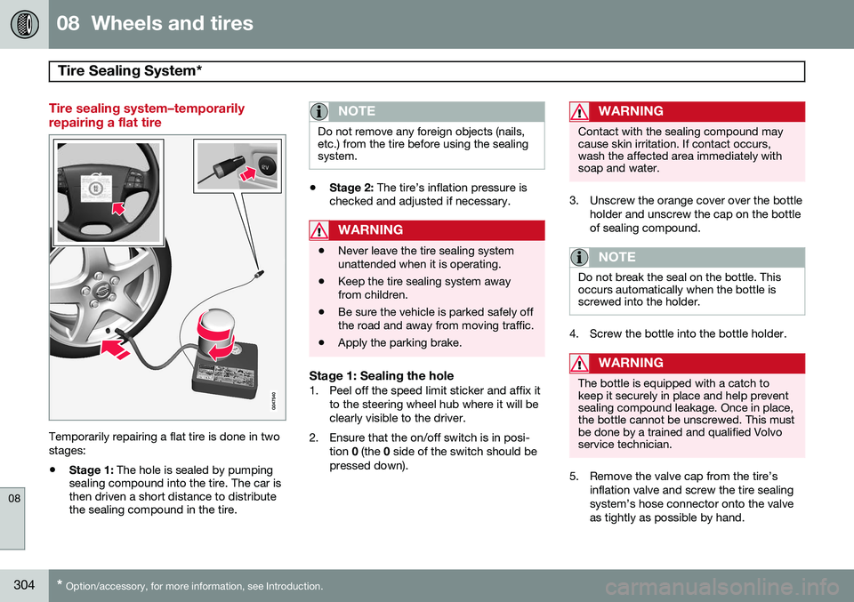
Tire sealing system–temporarily repairing a flat tire
Temporarily repairing a flat tire is done in two stages:
• Stage 1:
The hole is sealed by pumping
sealing compound into the tire. The car is then driven a short distance to distributethe sealing compound in the tire.
NOTE
Do not remove any foreign objects (nails, etc.) from the tire before using the sealingsystem.
• Stage 2:
The tire’s inflation pressure is
checked and adjusted if necessary.
WARNING
• Never leave the tire sealing system unattended when it is operating.
• Keep the tire sealing system awayfrom children.
• Be sure the vehicle is parked safely offthe road and away from moving traffic.
• Apply the parking brake.
Stage 1: Sealing the hole1. Peel off the speed limit sticker and affix it
to the steering wheel hub where it will be clearly visible to the driver.
2. Ensure that the on/off switch is in posi- tion 0 (the 0 side of the switch should be
pressed down).
WARNING
Contact with the sealing compound may cause skin irritation. If contact occurs,wash the affected area immediately withsoap and water.
3. Unscrew the orange cover over the bottle holder and unscrew the cap on the bottle of sealing compound.
NOTE
Do not break the seal on the bottle. This occurs automatically when the bottle isscrewed into the holder.
4. Screw the bottle into the bottle holder.
WARNING
The bottle is equipped with a catch to keep it securely in place and help preventsealing compound leakage. Once in place,the bottle cannot be unscrewed. This mustbe done by a trained and qualified Volvoservice technician.
5. Remove the valve cap from the tire’sinflation valve and screw the tire sealing system’s hose connector onto the valveas tightly as possible by hand.
Page 309 of 380

08 Wheels and tires
Tire Sealing System*
08
* Option/accessory, for more information, see Introduction.307
Inflating tires
The tire sealing system can be used to inflate the tires. To do so:
1. Park the car in a safe place.
2. The compressor should be switched off.
Ensure that the on/off switch is in position0 (the 0 side of the switch should be
pressed down).
3. Take out the electrical wire and hose.
4. Remove the valve cap from the tire’s inflation valve and screw the hose con- nector onto the valve as tightly as possi-ble by hand.
5. Connect the electrical wire to the nearest 12-volt socket in the vehicle.
6. Start the vehicle’s engine.WARNING
• The vehicle’s engine should be running when the tire sealing system is used toavoid battery drain. Therefore, be surethe vehicle is parked in a well ventilatedplace, or outdoors, before using thesystem. The parking brake should besecurely applied and the gear selectorshould be in the
P (park) position.
• Children should never be left unatten-ded in the vehicle when the engine isrunning.
7. Check the tire’s inflation pressure on the
gauge. Switch off the compressor briefly to get a clear reading from the pressuregauge.
8. Refer to the tire inflation table in this chapter for the correct inflation pressure.If the tire needs to be inflated, start thetire sealing system’s compressor (pressthe on/off switch to position I). If neces-sary, release air from the tire by turningthe air release knob counterclockwise.
CAUTION
The compressor should not be used for more than 10 minutes at a time to avoidoverheating.
9. Turn off the compressor (press the on/off switch to position 0) when the correct
inflation pressure has been reached.
10. Unscrew the hose from the tire’s inflation valve and reinstall the valve cap.
CAUTION
•After pumping the tires, always reinstall the valve cap to help avoid damage tothe valve from dirt, gravel, etc.
• Use plastic valve caps only. Metal capscould corrode and become difficult toremove.
11. Disconnect the electrical wire from the
12-volt socket.
Page 310 of 380

08 Wheels and tires
Changing a wheel
08
308* Option/accessory, for more information, see Introduction.
Removing a wheel
G014341
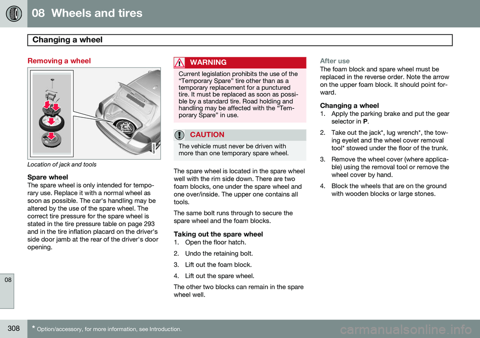
Location of jack and tools
Spare wheelThe spare wheel is only intended for tempo- rary use. Replace it with a normal wheel assoon as possible. The car's handling may bealtered by the use of the spare wheel. Thecorrect tire pressure for the spare wheel isstated in the tire pressure table on page 293and in the tire inflation placard on the driver'sside door jamb at the rear of the driver's dooropening.
WARNING
Current legislation prohibits the use of the “Temporary Spare” tire other than as atemporary replacement for a puncturedtire. It must be replaced as soon as possi-ble by a standard tire. Road holding andhandling may be affected with the “Tem-porary Spare” in use.
CAUTION
The vehicle must never be driven with more than one temporary spare wheel.
The spare wheel is located in the spare wheel well with the rim side down. There are twofoam blocks, one under the spare wheel andone over/inside. The upper one contains alltools. The same bolt runs through to secure the spare wheel and the foam blocks.
Taking out the spare wheel1. Open the floor hatch.
2. Undo the retaining bolt.
3. Lift out the foam block.
4. Lift out the spare wheel.The other two blocks can remain in the spare wheel well.
After useThe foam block and spare wheel must be replaced in the reverse order. Note the arrowon the upper foam block. It should point for-ward.
Changing a wheel1. Apply the parking brake and put the gear
selector in P.
2. Take out the jack*, lug wrench*, the tow- ing eyelet and the wheel cover removaltool* stowed under the floor of the trunk.
3. Remove the wheel cover (where applica- ble) using the removal tool or remove thewheel cover by hand.
4. Block the wheels that are on the ground with wooden blocks or large stones.