2014 VOLKSWAGEN TRANSPORTER ECU
[x] Cancel search: ECUPage 416 of 486
Vehicle toolkit
CCll Introduction
This chapter contains information on the following subjects:
Stowage Contents 416 417
Observe any country-specific legislation when se-curing your vehicle in the event of a breakdown.
Additional information and warnings:
• Seat functions, passenger compartment 72
• Stowage =>page 150
• Preparation for working in the engine compart-ment page 350
• In an emergency =>page 411
• Changing a wheel 420
• Breakdown set =>page 425
Stowage
r-111 First read and observe the introductory L-J,::.U information and safety warnings & on page 416.
Model Stowage
A WARNING
In the event of a sudden driving or braking manoeuvre or accident, a loose vehicle tools container, breakdown set and spare wheel could be flung though the vehicle and cause severe injuries.
• Always ensure that the vehicle toolkit, breakdown set and spare wheel are secured safely in the vehicle.
A WARNING
Unsuitable or damaged tools in the vehicle tool kit can lead to accidents and injuries.
• Never work with unsuitable or damaged tools from the vehicle toolklt.
Action
In the luggage compartment Loosen securing strap if necessarya)_ Multivan, California Beach possibly above the left-hand If necessary, loosen the bolt to remove rear wheel housing: the vehicle jack.
In the stowage compartment California Coast and Ocean on the rear of the bench sea V Open the stowage compartment. bed:
•I In vehicles with a 3-seat bench in the fourth row of seats, the 3-seat bench needs to be supported with the support rod so you can reach the vehicle toolkit , page 72
After using the vehicle jack, crank it back to its original position so that it can be stored safely.
Page 417 of 486
Contents
,...-'('n First read and observe the introductory L-J,:,JJ Information and safety warnings & on page 416.
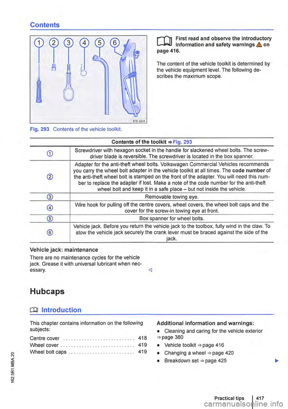
The content of the vehicle tool kit is determined by the vehicle equipment level. The following de-scribes the maximum scope.
Fig. 293 Contents of the vehicle tool kit.
®
®
Contents of the tool kit =>Fig. 293
Screwdriver with hexagon socket in the handle for slackened wheel bolts. The screw-driver blade is reversible. The screwdriver is located in the box spanner.
Adapter for the anti-theft wheel bolts. Volkswagen Commercial Vehicles recommends you carry the wheel bolt adapter in the vehicle tool kit at all times. The code number of the anti-theft wheel bolt is stamped on the front of the adapter. You will need this num-ber to replace the adapter if lost. Make a note of the code number for the anti-theft wheel bolt and keep it in a safe place-but not inside the vehicle.
Removable towing eye.
Wire hook for pulling off the centre covers, wheel covers, the wheel bolt caps and the cover for the screw-in towing eye at front.
Box spanner for wheel bolts.
Vehicle jack. Before you return the vehicle jack to the tool box, fully wind in the claw. To stow the vehicle jack securely the crank lever must be braced against the side of the jack.
Vehicle jack: maintenance
There are no maintenance cycles for the vehicle jack. Grease it with universal lubricant when nec-essary.
COl Introduction
This chapter contains information on the following subjects:
Centre cover ... .
Wheel cover .. . Wheel bolt caps ..
418 419 419
Additional information and warnings:
• Cleaning and caring for the vehicle exterior =>page 380
• Vehicle tool kit =>page 416
• Changing a wheel =>page 420
• Breakdown set =>page 425
Practical tips I 417
Page 419 of 486
Wheel cover
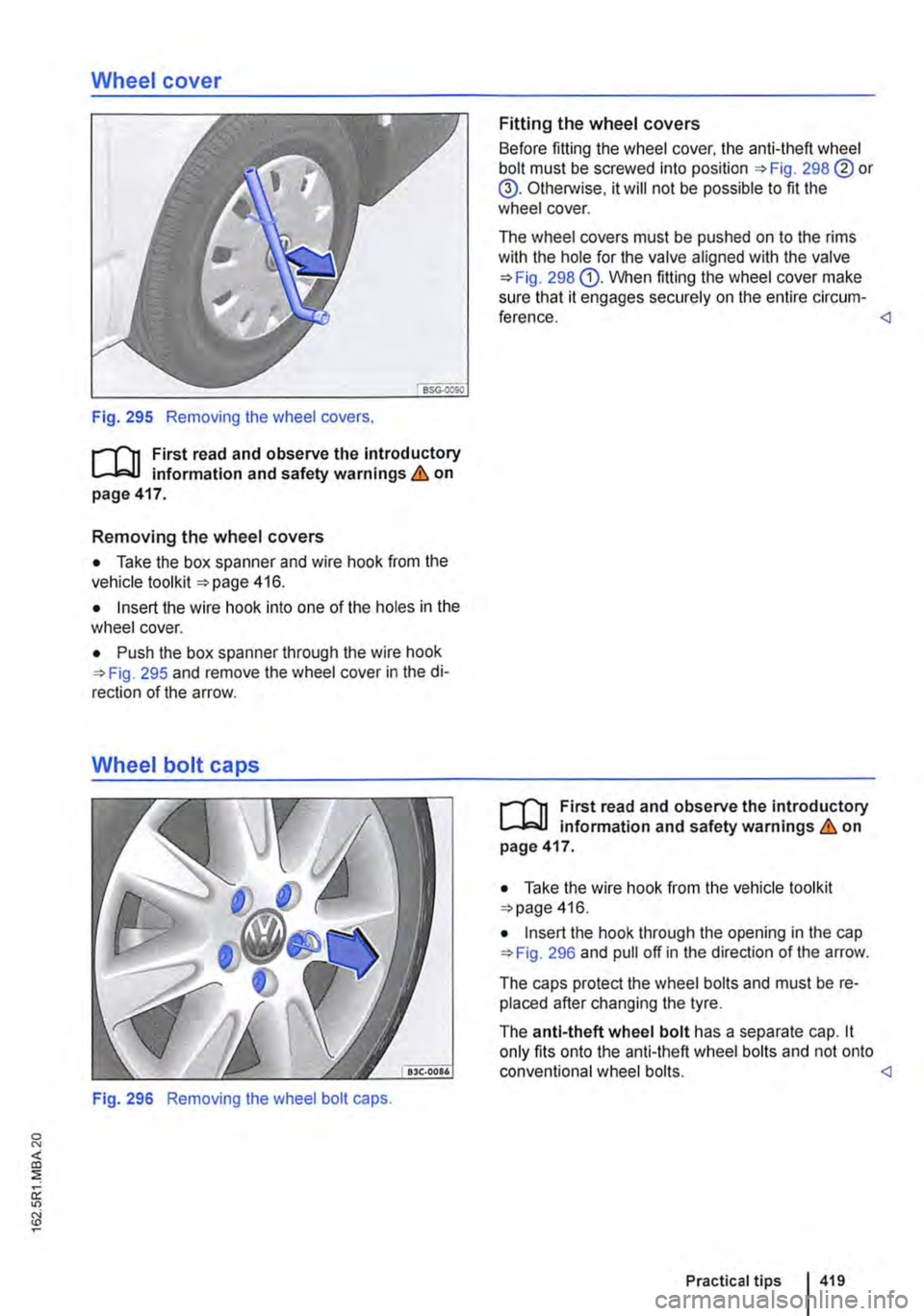
Fig. 295 Removing the wheel covers.
r-f"n First read and observe the Introductory information and safety warnings & on page 417.
Removing the wheel covers
• Take the box spanner and wire hook from the vehicle toolkit 416.
• Insert the wire hook into one of the holes in the wheel cover.
• Push the box spanner through the wire hook 295 and remove the wheel cover in the di-rection of the arrow.
Fig. 296 Removing the wheel bolt caps.
Fitting the wheel covers
Before fitting the wheel cover, the anti-theft wheel bolt must be screwed into position 298 ®or @. Otherwise, it will not be possible to fit the wheel cover.
The wheel covers must be pushed on to the rims with the hole for the valve aligned with the valve 298 G). When fitting the wheel cover make sure that it engages securely on the entire circum-ference.
• Take the wire hook from the vehicle tool kit 416.
• Insert the hook through the opening in the cap 296 and pull off in the direction of the arrow.
The caps protect the wheel bolts and must be re-placed after changing the tyre.
The anti-theft wheel bolt has a separate cap. it only fits onto the anti-theft wheel bolts and not onto conventional wheel bolts.
Page 421 of 486
Checklist (Continued)
8. VI/hen towing a trailer, unhitch the trailer from the vehicle and park it properly.
9. Remove any items of luggage from the lug-gage compartment.
10. Remove the spare wheel and vehicle tools from the vehicle.
11. Remove the hubcaps =>page 417.
Wheel bolts
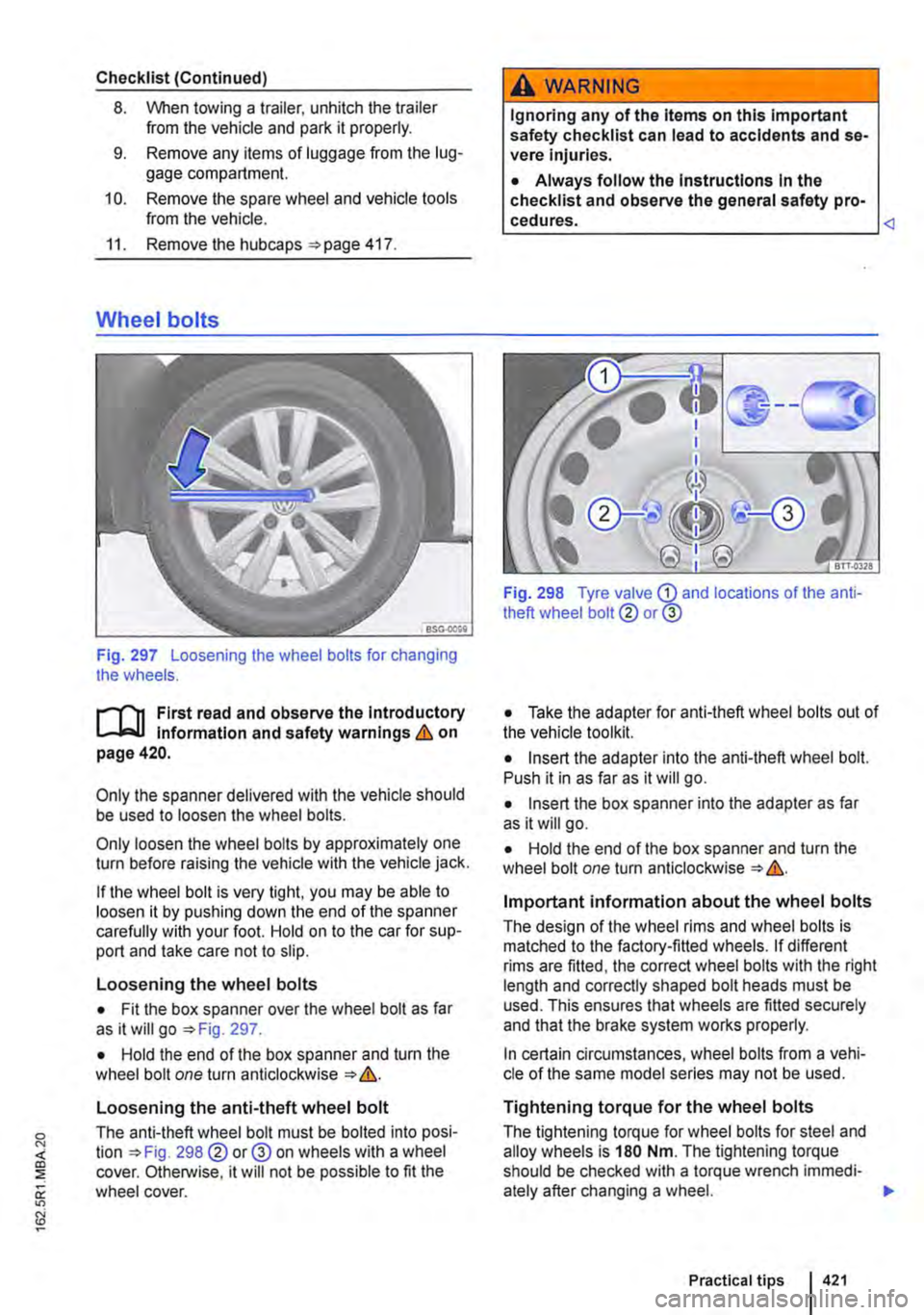
Fig. 297 Loosening the wheel bolts for changing the wheels.
r-"f"'n First read and observe the Introductory l.-J,:..LJ Information and safety warnings & on page420.
Only the spanner delivered with the vehicle should be used to loosen the wheel bolts.
Only loosen the wheel bolts by approximately one turn before raising the vehicle with the vehicle jack.
If the wheel bolt is very tight, you may be able to loosen it by pushing down the end of the spanner carefully with your foot. Hold on to the car for sup-port and take care not to slip.
Loosening the wheel bolts
• Fit the box spanner over the wheel bolt as far as it will go =>Fig. 297.
• Hold the end of the box spanner and turn the wheel bolt one turn anticlockwise => &.
Loosening the anti-theft wheel bolt
The anti-theft wheel bolt must be bolted into posi-tion =>Fig. 298@ or@ on wheels with a wheel cover. Otherwise, it will not be possible to fit the wheel cover.
A WARNING
Ignoring any of the Items on this Important safety checklist can lead to accidents and se-vere Injuries.
• Always follow the Instructions In the checklist and observe the general safety pro-
Fig. 298 Tyre valve G) and locations of the anti-theft wheel bolt@ or@
• Take the adapter for anti-theft wheel bolts out of the vehicle toolkit.
• Insert the adapter into the anti-theft wheel bolt. Push it in as far as it will go.
• Insert the box spanner into the adapter as far as it will go.
• Hold the end of the box spanner and turn the wheel bolt one turn anticlockwise => &.
Important information about the wheel bolts
The design of the wheel rims and wheel bolts is matched to the factory-fitted wheels. If different rims are fitted, the correct wheel bolts with the right length and correctly shaped bolt heads must be used. This ensures that wheels are fitted securely and that the brake system works properly.
In certain circumstances, wheel bolts from a vehi-cle of the same model series may not be used.
Tightening torque for the wheel bolts
The tightening torque for wheel bolts for steel and alloy wheels is 180 Nm. The tightening torque should be checked with a torque wrench immedi-ately after changing a wheel. .,.
Practical tips 421
Page 424 of 486

Checklist (Continued)
7. Raise the vehicle jack until it just fits under the jacking point of the vehicle.
8. Make sure that the foot of the jack is resting securely on the ground with its whole sur-face and that its axis of rotation is posi-tioned precisely, i.e. vertically beneath the point of application. For better clarity, extend the line from the point of application to the axis of rotation of the jack foot =>Fig. 300.
9. Position the vehicle jack. At the same time, continue to crank the claw up until it is in po-sition around the vertical rib underneath the vehicle => Fig. 300.
10. Crank the vehicle jack further until the wheel is just clear of the ground.
A WARNING
Incorrect use of the vehicle jack can cause the vehicle to slip off the jack, which can lead to severe Injuries. Please note the following points In order to reduce the risk of Injuries:
• Only use vehicle jacks which have been approved by Volkswagen Commercial Vehi-cles for your vehicle type. Other vehicle jacks could slip out of position-this Includes vehi-cle jacks supplied with other Volkswagen models.
• The ground must be firm and level. Soft ground or surfaces at an Incline under the ve-hicle jack may cause the vehicle to slip off the jack. If necessary use a large, strong board or similar support for the vehicle jack.
Changing a wheel
Fig. 301 removing the wheel bolts with the screw-driver handle.
424 If and when
A WARNING (ConUnued)
• On a hard, slippery surface (such as tiles) use a rubber mat or similar to prevent the ve-hicle jack from slipping.
• Fit the vehicle jack only at the points de-scribed. The vehicle jack claw must grip the vertical rib under the door sill securely =>Fig. 300.
• Never place any part of your body (e.g. an arm or leg) underneath the vehicle If the latter Is only supported by the vehicle jack.
• If you have to work underneath the vehi-cle, use suitable stands to provide extra sup-port for the vehicle.
• Never lift the vehicle when the engine is running, or If the vehicle is tilted to the side or on a gradient
• Never start the engine when the vehicle is raised on a vehicle jack. Engine vibrations can cause the vehicle to fall off the vehicle jack.
A WARNING
Ignoring any of the Items on this Important safety checklist can lead to accidents and se-vere Injuries.
• Always follow the Instructions In the checklist and observe the general safety pro-
r--('n First read and observe the introductory L-J.:.I.J information and safety warnings & on page 420.
Removing the wheel
• Read the checklist =>page 420.
• Loosen the wheel bolts =>page 421.
• Jack up the vehicle =>page 423.
• Using the hexagonal socket in the screwdriver handle =>Fig. 301, unscrew the loosened wheel bolts, remove and place on a clean surface.
• Remove the wheel.
Fitting the spare wheel
Note any specific tyre running direction =>page 367.
Page 425 of 486
• Clean the area around the fastening holes of the spare wheel.
• Position the spare wheel.
• Insert the anti-theft wheel bolt using the adapter at position 298 @or® and tighten it slight-ly.
• Screw in all the other wheel bolts in a clockwise direction and use the box spanner to tighten them gently.
• Lower the vehicle with the jack.
• Use the box spanner to tighten all the wheel bolts securely in a clockwise direction &. Do not tighten the bolts in clockwise or anticlockwise se-quence. Tighten them in diagonal sequence.
• Fit the cover caps, centre covers or wheel cov-ers 417.
After changing a wheel
rl'l1 First read and observe the Introductory L-.lo:.ll Information and safety warnings & on page 420.
• If necessary, clean the vehicle tools and stow them safely in the vehicle 416.
• Stow the spare wheel or the removed wheel safely under the vehicle.
Breakdown set
CQJ Introduction
This chapter contains information on the following subjects:
Storing . . . . . . . . . . . . . . . . . . . . 426
Contents of the breakdown set . . . . . . . . . . . . 427 Preparation . . . . . . . . . . . . . . . . . . . . . . . . . . . 427
Sealing and inflating tyres . . . . • . . . . . . . 428
Test after driving for 10 minutes . . . . 429
You can use the breakdown set (tyre mobility set) to safely seal any tyre damage caused by foreign bodies or punctures (up to 4 mm (0.16 Inches) in diameter). Do not remove foreign objects (e.g. screws or nails) from the tyrel
Once the sealant has been added to the tyre, the tyre pressure must be checked again after approxi-mately 10 minutes of driving.
,A WARNING
Incorrect torque or incorrect use of wheel bolts can lead to a loss of control of the vehi-cle, cause accidents and serious Injuries.
• Always keep all wheel bolts and threads In the wheel hubs clean and free from oil and grease. The wheel bolts must be easy to turn and be tightened to the specified torque.
• The hexagonal socket In the screwdriver handle should only be used for turning wheel bolts, not use for loosening or tightening them.
• The damaged wheel should be replaced as soon as possible.
m In vehicles with a tyre monitoring system, the L!..J system may have to "re-learn" if new tyres are fitted 318.
Only use the breakdown set if the car is parked in a safe place, you are familiar with the required ac-tions and safety procedures, and you have access to the correct breakdown set. Seek expert assis-tance if this is not the case.
The tyre sealant must not be used:
• If the rim is damaged.
• If the outside temperature is below -2o•c (-4 ·F).
• If there are cuts or punctures in the tyre that are larger than 4 mm. .,.
Practical tips 425
Page 431 of 486
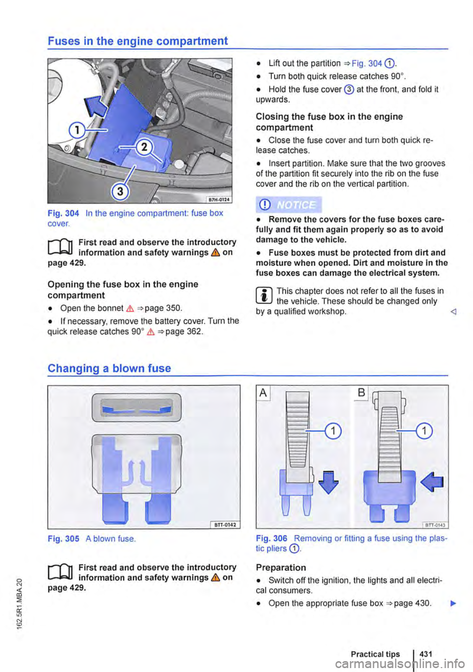
Fig. 304 In the engine compartment: fuse box cover.
;-('n First read and observe the introductory L-Jc.IJ information and safety warnings & on page 429.
Opening the fuse box in the engine compartment
• Open the bonnet .1. =<>page 350.
• If necessary, remove the battery cover. Turn the quick release catches go• .1. =<>page 362.
Changing a blown fuse
Fig. 305 A blown fuse.
;-('n First read and observe the introductory L-Jc.IJ information and safety warnings & on page 429.
• Lift out the partition =<>Fig. 304 0).
• Turn both quick release catches go•.
• Hold the fuse cover@ at the front. and fold it upwards.
Closing the fuse box in the engine compartment
• Close the fuse cover and turn both quick re-lease catches.
• Insert partition. Make sure that the two grooves of the partition fit securely into the rib on the fuse cover and the rib on the vertical partition.
CD
• Remove the covers for the fuse boxes care-fully and fit them again properly so as to avoid damage to the vehicle.
• Fuse boxes must be protected from dirt and moisture when opened. Dirt and moisture in the fuse boxes can damage the electrical system.
m This chapter does not refer to all the fuses in L!J the vehicle. These should be changed only by a qualified workshop.
Preparation
• Switch off the ignition, the lights and all electri-cal consumers.
• Open the appropriate fuse box =<>page 430. .,..
Practical tips I 431
Page 440 of 486
![VOLKSWAGEN TRANSPORTER 2014 Owners Manual The actions should only be carried out in the specified order:
8. Close the service flap CD in the wheel housing liner.
Bulb H11 <]
Fig. 313 Changing the tail light bulbs.
ro First read and observ VOLKSWAGEN TRANSPORTER 2014 Owners Manual The actions should only be carried out in the specified order:
8. Close the service flap CD in the wheel housing liner.
Bulb H11 <]
Fig. 313 Changing the tail light bulbs.
ro First read and observ](/manual-img/18/55783/w960_55783-439.png)
The actions should only be carried out in the specified order:
8. Close the service flap CD in the wheel housing liner.
Bulb H11 <]
Fig. 313 Changing the tail light bulbs.
ro First read and observe the introductory Information and safety warnings & on page 432.
The actions should only be carried out in the specified order:
Brake light/tail Rear fog light bulb '*Fig. 313 Tail light bulb Turn signal bulb light bulb or reversing light bulb
1. Observe and follow the instructions on the checklist =>page 433.
2. Unscrew the two securing bolts G).
3. Push the tail light cluster towards the outside out of the mounting, release the connec-tor, and pull it off the bulb holder.
4. Unscrew the four securing bolts@, and pull the bulb holder@ out of the tail light cl us-ter.
Push the bulb® Push the bulb 0 Pull the bulb@ Pull the bulb ® slightly into the bulb slightly into the bulb 5. straight out of the straight out of the holder, turn it anti-holder, turn it anti-bulb holder. bulb holder. clockwise, and pull it clockwise, and pull it out straight. out straight.
6. Replace the defective bulb with a new bulb of the same type (see the last line in the table "Bulbs").
7. Insert the bulb holder into the tail light cluster and tighten the bolts.
8. Carefully insert the tail light cluster into the body so that it is flush with the vehicle body-work, and tighten the bolts.
Bulb W5W I W16W I P21/4W I H21Wor P21W <]
440 I If and whon