Page 52 of 201

50Seats, restraints9Warning
Keep the area in which the airbag
inflates clear of obstructions.
Notice
Only use protective seat covers that have been approved for the vehicle.Be careful not to cover the airbags.
Airbag deactivation Front airbag and side airbag systems
for the front passenger seat must be
deactivated if a child restraint system is to be fitted on this seat. The belt
pretensioners and all driver airbag
systems will remain active.
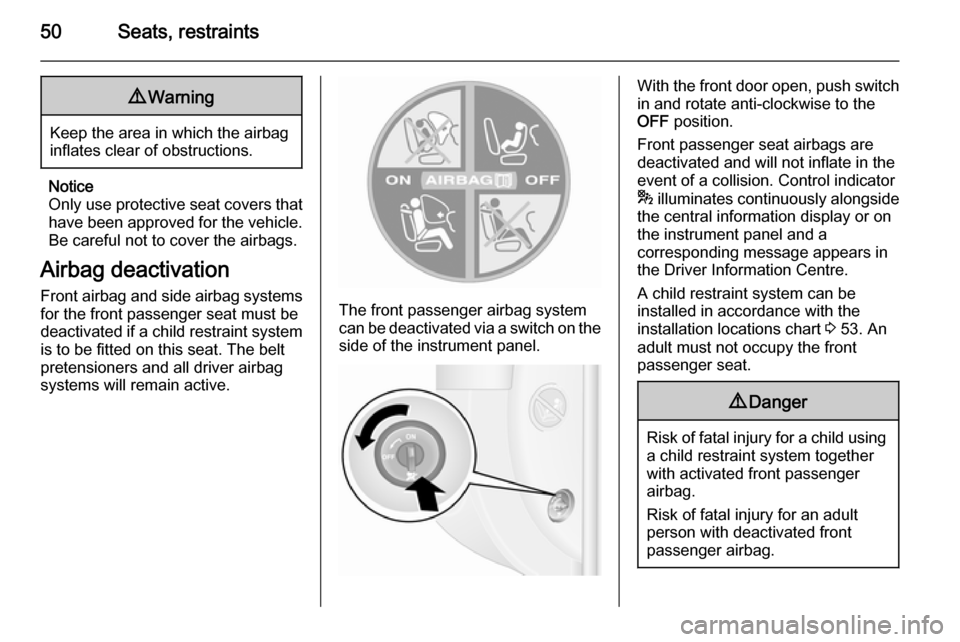
The front passenger airbag system
can be deactivated via a switch on the
side of the instrument panel.
With the front door open, push switch in and rotate anti-clockwise to the
OFF position.
Front passenger seat airbags are
deactivated and will not inflate in the event of a collision. Control indicator
* illuminates continuously alongside
the central information display or on
the instrument panel and a
corresponding message appears in
the Driver Information Centre.
A child restraint system can be
installed in accordance with the
installation locations chart 3 53. An
adult must not occupy the front
passenger seat.9 Danger
Risk of fatal injury for a child using
a child restraint system together
with activated front passenger
airbag.
Risk of fatal injury for an adult
person with deactivated front
passenger airbag.
Page 73 of 201

Instruments and controls719Warning
The road surface may already be
icy even though the display
indicates a few degrees above 0
°C.
Clock
Depending on vehicle, the current
time and/or date may appear in the
information display 3 83 or the
Driver Information Centre 3 83.
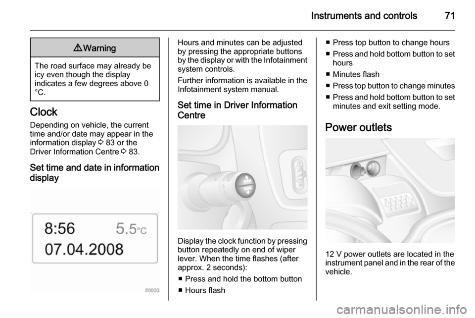
Set time and date in information display
Hours and minutes can be adjusted
by pressing the appropriate buttons
by the display or with the Infotainment
system controls.
Further information is available in the
Infotainment system manual.
Set time in Driver Information
Centre
Display the clock function by pressing button repeatedly on end of wiper
lever. When the time flashes (after
approx. 2 seconds):
■ Press and hold the bottom button
■ Hours flash
■ Press top button to change hours
■ Press and hold bottom button to set
hours
■ Minutes flash
■ Press top button to change minutes
■ Press and hold bottom button to set
minutes and exit setting mode.
Power outlets
12 V power outlets are located in the instrument panel and in the rear of the
vehicle.
Page 85 of 201
Instruments and controls83Information displaysDriver Information Centre
Depending on vehicle configuration,
the following items appear in the
display:
■ Outside temperature 3 70
■ Clock 3 71
■ Odometer, trip odometer 3 73
■ Engine oil level monitor 3 74
■ Service display 3 75
■ Vehicle messages 3 83
■ Trip computer 3 85
Triple-Info-Display
Displays time, outside temperature
and date when the ignition is on.
Vehicle messages
Messages appear in the Driver
Information Centre, in combination
with control indicator A or C.
Information messagesInformation messagesBATTERY MODE: ECONOMYESP OFFAUTO LIGHTS DEACTIVATEDOIL LEVEL CORRECT
Fault messages Displayed in combination with control
indicator A. Drive with caution and
seek the assistance of a workshop.
To remove fault message, press
button on end of wiper lever. After a
few seconds the message may
disappear automatically and A
Page 87 of 201

Instruments and controls85Trip computer
The trip computer provides
information on driving data, which is
continually recorded and evaluated electronically.
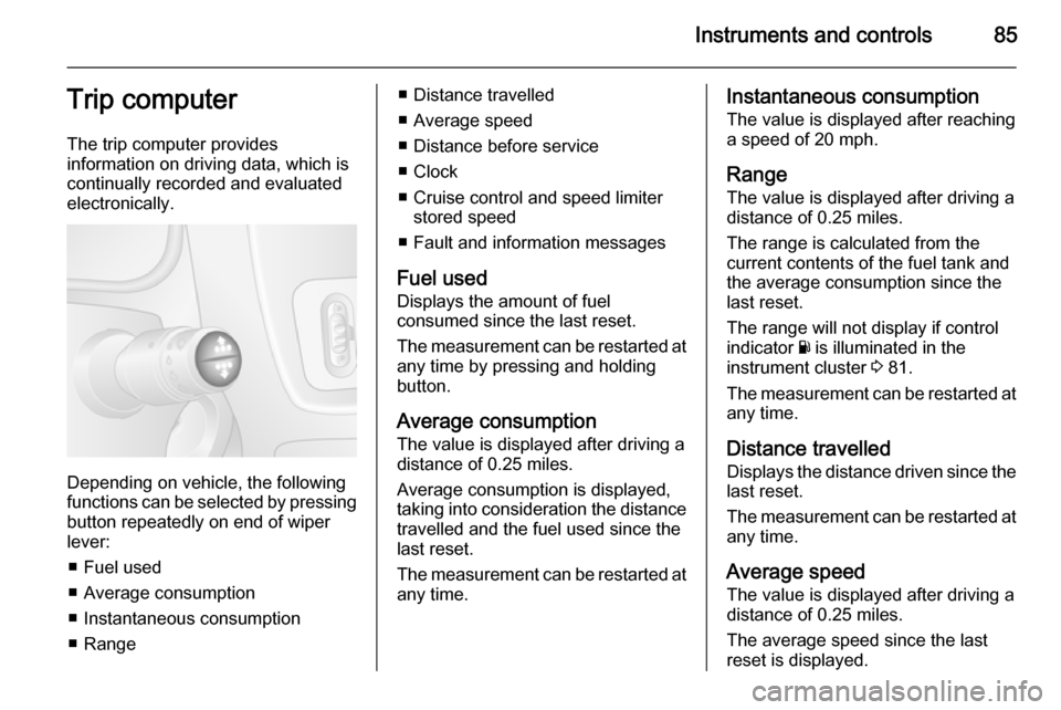
Depending on vehicle, the following
functions can be selected by pressing button repeatedly on end of wiper
lever:
■ Fuel used
■ Average consumption
■ Instantaneous consumption
■ Range
■ Distance travelled
■ Average speed
■ Distance before service
■ Clock
■ Cruise control and speed limiter stored speed
■ Fault and information messages
Fuel used Displays the amount of fuel
consumed since the last reset.
The measurement can be restarted at
any time by pressing and holding
button.
Average consumption
The value is displayed after driving a distance of 0.25 miles.
Average consumption is displayed,
taking into consideration the distance
travelled and the fuel used since the
last reset.
The measurement can be restarted at
any time.Instantaneous consumption
The value is displayed after reaching
a speed of 20 mph.
Range The value is displayed after driving a
distance of 0.25 miles.
The range is calculated from the
current contents of the fuel tank and
the average consumption since the
last reset.
The range will not display if control
indicator Y is illuminated in the
instrument cluster 3 81.
The measurement can be restarted at
any time.
Distance travelled Displays the distance driven since the
last reset.
The measurement can be restarted at
any time.
Average speed The value is displayed after driving adistance of 0.25 miles.
The average speed since the last
reset is displayed.
Page 101 of 201
Climate control99
Neutral position or no stored
programme activated Press P button until their is no stored
programme number visible in the
display.
Adjusting the temperature To adjust the temperature of the
heating, turn the rotary knob located
on the control panel.Turn
clockwise=increase temperatureTurn anti-
clockwise=decrease temperature
Rear air conditioning
system
The rear air conditioning system is
actuated in conjunction with the front
passenger compartment air
conditioning system.
Bus
Rear air vents
Additional air conditioning is supplied
to the rear passenger compartment
via the overhead air vents.
Fan speed
Adjust the air flow to select the
desired speed.
turn clockwise=increase air flowturn anti-clock‐
wise=decrease air flow
Combi
Additional air conditioning is supplied to the rear passenger compartment
via the air vents located above the
driver and front passenger
compartment.
Page 130 of 201

128Driving and operating
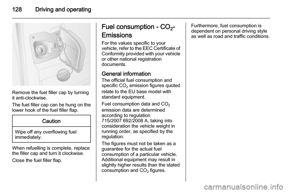
Remove the fuel filler cap by turning
it anti-clockwise.
The fuel filler cap can be hung on the lower hook of the fuel filler flap.
Caution
Wipe off any overflowing fuel
immediately.
When refuelling is complete, replace
the filler cap and turn it clockwise.
Close the fuel filler flap.
Fuel consumption - CO 2-
Emissions
For the values specific to your
vehicle, refer to the EEC Certificate of
Conformity provided with your vehicle or other national registration
documents.
General information The official fuel consumption and
specific CO 2 emission figures quoted
relate to the EU base model with
standard equipment.
Fuel consumption data and CO 2
emission data are determined
according to regulation
715/2007 692/2008 A, taking into
consideration the vehicle weight in
running order, as specified by the regulation.
The figures must not be taken as a
guarantee for the actual fuel
consumption of a particular vehicle.
Additional equipment may result in
slightly higher results than the stated
consumption and CO 2 figures.Furthermore, fuel consumption is
dependent on personal driving style
as well as road and traffic conditions.
Page 143 of 201
Vehicle care141
3. Release spring clip.
4. Withdraw bulb from reflector housing.
5. Renew bulb and secure with spring clip.
6. Reattach wiring connector to bulb.
7. Replace headlamp protective cover.
Low beam
1. Remove headlamp protective cover.
2. Detach wiring connector from bulb.
3. Rotate bulb holder anti-clockwise to disengage.
4. Withdraw bulb holder from reflector housing.
5. Detach bulb from bulb holder andrenew the bulb.
6. Insert the bulb holder, engaging the two lugs in the reflectorhousing and rotate clockwise to
secure.
7. Reattach wiring connector to bulb.
8. Replace headlamp protective cover.
Page 144 of 201
142Vehicle care
Sidelights
1. Remove protective cover.
2. Detach wiring connector from bulb.
3. Rotate bulb holder anti-clockwise to disengage.
4. Withdraw bulb holder from reflector housing.
5. Detach bulb from bulb holder andrenew the bulb.
6. Insert the bulb holder, engaging the two lugs in the reflectorhousing and rotate clockwise to
secure.
7. Reattach wiring connector to bulb.
8. Replace protective cover.
Adaptive forward lighting
Cornering light
Headlights have separate systems forhigh beam 1 and low beam 2. The
cornering light 3 is located between
the headlights.
1. Remove protective cover.
2. Detach wiring connector from bulb.
3. Rotate bulb holder anti-clockwise to disengage.
4. Withdraw bulb holder from reflector housing.