2014 VAUXHALL MOVANO_B parking brake
[x] Cancel search: parking brakePage 121 of 201

Driving and operating119Parking brake
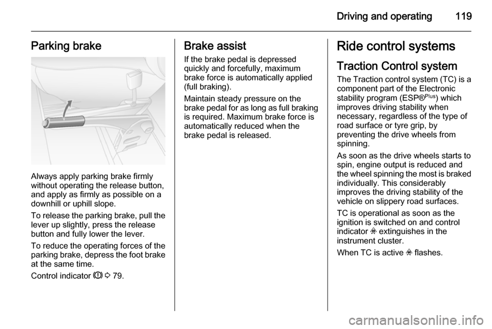
Always apply parking brake firmly
without operating the release button,
and apply as firmly as possible on a
downhill or uphill slope.
To release the parking brake, pull the lever up slightly, press the release
button and fully lower the lever.
To reduce the operating forces of the
parking brake, depress the foot brake
at the same time.
Control indicator R 3 79.
Brake assist
If the brake pedal is depressed
quickly and forcefully, maximum
brake force is automatically applied
(full braking).
Maintain steady pressure on the
brake pedal for as long as full braking
is required. Maximum brake force is
automatically reduced when the
brake pedal is released.Ride control systems
Traction Control system
The Traction control system (TC) is a
component part of the Electronic
stability program (ESP® Plus
) which
improves driving stability when
necessary, regardless of the type of
road surface or tyre grip, by
preventing the drive wheels from
spinning.
As soon as the drive wheels starts to spin, engine output is reduced and
the wheel spinning the most is braked individually. This considerably
improves the driving stability of the
vehicle on slippery road surfaces.
TC is operational as soon as the
ignition is switched on and control
indicator v extinguishes in the
instrument cluster.
When TC is active v flashes.
Page 134 of 201

132Vehicle careVehicle careGeneral Information...................132
Vehicle checks ........................... 133
Bulb replacement .......................140
Electrical system ........................148
Vehicle tools .............................. 150
Wheels and tyres .......................151
Jump starting ............................. 160
Towing ....................................... 162
Appearance care .......................164General Information
Accessories and vehicle
modifications
We recommend the use of genuine parts and accessories and factory
approved parts specific for your
vehicle type. We cannot assess or
guarantee reliability of other products
- even if they have a regulatory or
otherwise granted approval.
Do not make any modifications to the electrical system, e.g. changes of
electronic control units (chip tuning).
Vehicle storage Storage for a long period of time
The following tasks must be carried
out if the vehicle is to be stored for several months:
■ Wash and wax the vehicle.
■ Have the wax in the engine compartment and underbody
checked.
■ Clean and preserve rubber seals.■ Change engine oil.
■ Drain washer fluid reservoir.
■ Check coolant antifreeze.
■ Adjust tyre pressure to the value specified for full load.
■ Park vehicle in a dry, well ventilated
place.Engage first or reverse
gear.Prevent the vehicle from
rolling.
■ Do not apply parking brake.
■ Open bonnet, close all doors and lock the vehicle.
■ Disconnect the clamp from the negative terminal of the vehicle
battery.Beware that all systems are
not functional, e.g. anti-theft alarm
system.
Putting back into operation
The following tasks must be carried
out if the vehicle is being put back into operation:
■ Connect the clamp to the negative terminal of the vehicle
battery.Activate the electronics of
the power windows.
■ Check tyre pressure.
Page 156 of 201

154Vehicle care
Always use fine mesh chains that addno more than 15 mm to the tyre tread
and the inboard sides (including chain
lock).9 Warning
Damage may lead to tyre blowout.
Wheel covers on steel wheels may
come into contact with parts of the
chains. In such cases, remove the
wheel covers.
Tyre chains may only be used at
speeds up to 30 mph and, when
travelling on roads that are free of
snow, they may only be used for brief
periods since they are subject to rapid wear on a hard road and may snap.
The use of tyre chains is not permitted on the temporary spare wheel.
Tyre repair kit
Minor damage to the tyre tread can be
repaired with the tyre repair kit.
Do not remove foreign bodies from
the tyres.
Tyre damage exceeding 4 mm or that
is at the tyre's sidewall near the rim
cannot be repaired with the tyre repair kit.9 Warning
Do not drive faster than 50 mph.
Do not use for a lengthy period.
Steering and handling may be
affected.
If the vehicle has a flat tyre:
Apply the parking brake and engage
first gear or reverse gear.
The tyre repair kit is located under the
front seat. Slide seat forwards fully
and fold backrest down to access kit.
1. Take the tyre repair kit out from under the front seat.
2. Remove the compressor.
3. Remove the power supply lead and air hose from the stowage
compartments on the underside
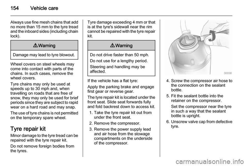
of the compressor.4. Screw the compressor air hose to
the connection on the sealant
bottle.
5. Fit the sealant bottle into the retainer on the compressor.
Set the compressor near the tyre
in such a way that the sealant
bottle is upright.
6. Unscrew valve cap from defective
tyre.
Page 159 of 201

Vehicle care157
not be driven. Seek theassistance of a workshop.
20. Stow tyre repair kit under the front
seat.
Notice
The driving characteristics of the repaired tyre are severely affected, therefore have this tyre replaced.
If unusual noise is heard or the
compressor becomes hot, turn
compressor off for at least
30 minutes.
The built-in safety valve opens at a
pressure of 7 bar (102 psi).
Note the expiry date of the kit. After
this date its sealing capability is no
longer guaranteed. Pay attention to
storage information on sealant
bottle.
Replace the used sealant bottle. Dispose of the bottle as prescribed
by applicable laws.
The compressor and sealant can be used from approx. -30 °C.
The adapters supplied can be used
to pump up other items e.g.
footballs, air mattresses, inflatabledinghies etc. They are located on the underside of the compressor. To
remove, screw on compressor air hose and withdraw adapter.
Wheel changing Some vehicles are equipped with a
tyre repair kit instead of a spare wheel 3 154.
Make the following preparations and
observe the following information:
■ Park the vehicle on a level, firm and
non-slippery surface. The frontwheels must be in the straight-ahead position.
■ Apply the parking brake and engage first gear or reverse gear.
■ Switch off the air suspension system 3 110.
■ Remove the spare wheel 3 159.
■ Never change more than one wheel
at a time.
■ Use the jack only to change wheels
in case of puncture, not for
seasonal winter or summer tyre
change.■ If the ground on which the vehicle is standing is soft, a solid board
(max. 1 cm thick) should be placed
under the jack.
■ No people or animals may be in the
vehicle when it is jacked-up.
■ Never crawl under a jacked-up vehicle.
■ Do not start the engine when the vehicle is raised on the jack.
■ Clean wheel bolts/nuts and their threads before mounting the wheel.9 Warning
Do not grease wheel bolt, wheel
nut and wheel nut cone.
1. Remove the wheel cover using the hook supplied. Vehicle tools
3 150.
2. Install the wheel wrench ensuring that it locates securely and loosen
each wheel bolt/nut by half a turn.
Page 163 of 201

Vehicle care161Caution
The air suspension system must
be switched off prior to jump
starting.
9 Warning
Avoid contact of the battery with
eyes, skin, fabrics and painted
surfaces. The fluid contains
sulphuric acid which can cause
injuries and damage in the event
of direct contact.
■ Never expose the vehicle battery to
naked flames or sparks.
■ A discharged vehicle battery can already freeze at a temperature of
0 °C. Defrost the frozen vehicle
battery before connecting jump
leads.
■ Wear eye protection and protective
clothing when handling a vehicle
battery.
■ Use a booster battery with the same voltage (12 volts). Its capacity(Ah) must not be much less than
that of the discharged vehicle
battery.
■ Use jump leads with insulated terminals and a cross section of at
least 25 mm 2
.
■ Do not disconnect the discharged battery from the vehicle.
■ Switch off all unnecessary electrical
consumers.
■ Switch off the air suspension system.
■ Do not lean over the vehicle battery
during jump starting.
■ Do not allow the terminals of one lead to touch those of the other
lead.
■ The vehicles must not come into contact with each other during the
jump starting process.
■ Apply the parking brake, transmission in neutral.Jump start terminal
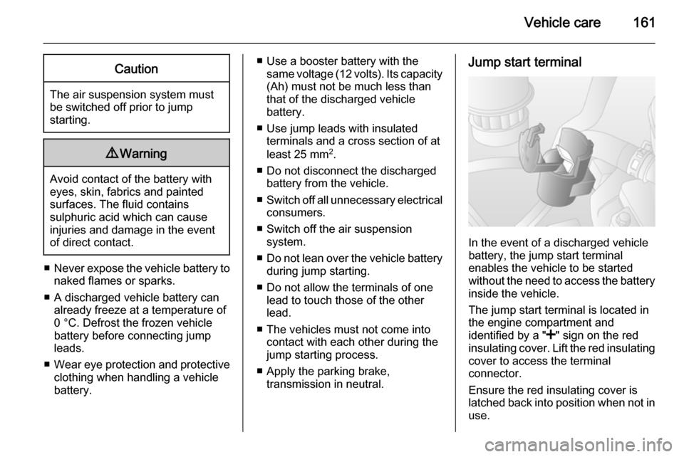
In the event of a discharged vehicle
battery, the jump start terminal
enables the vehicle to be started
without the need to access the battery inside the vehicle.
The jump start terminal is located in
the engine compartment and
identified by a " <" sign on the red
insulating cover. Lift the red insulating
cover to access the terminal
connector.
Ensure the red insulating cover is
latched back into position when not in
use.
Page 198 of 201

196
HHand brake - see Parking brake. 119
Hazard warning flashers ..............89
Headlight flash ............................. 88
Headlight range adjustment ........88
Headlights ...................... 87, 88, 140
Headlights when driving abroad ..88
Head restraint adjustment .............8
Head restraints ............................ 35
Heated mirrors ............................. 31
Heated rear window ..................... 33
Heating ........................................ 40
Heating and ventilation system ...94
High beam ............................. 82, 88
Horn ....................................... 13, 69
I
Identification plate .....................171
Idle speed control ......................108
Ignition switch positions .............107
Immobiliser .................................. 29
Indicators ...................................... 73
Information displays...................... 83
Instrument cluster ........................73
Instrument panel fuse box .........149
Instrument panel illumination .....147
Instrument panel overview ........... 10
Instrument panel storage .............60
Interior care ............................... 165Interior lighting.............................. 90
Interior lights ........................ 90, 146
Interior mirrors .............................. 31
Interruption of power supply ......117
Introduction .................................... 3
ISOFIX child restraint systems ....59
J Jack ............................................ 150
Jump starting ............................. 160
K Keys ............................................. 18
Keys, locks ................................... 18
L
Lashing eyes ............................... 63
Light covers, misted...................... 90
Lighting ......................................... 87
Light switch .................................. 87
Load compartment lighting ..........91
Loading information .....................66
Low fuel ....................................... 81
M Malfunction indicator light ............79
Manual adjustment ......................30
Manual anti-dazzle ......................31
Manual mode ............................. 116
Manual transmission .................. 113Manual transmission automated 114
Manual windows ..........................32
Messages ..................................... 83
Mirror adjustment ........................... 8
Mirrors .................................... 30, 31
Misted light covers .......................90
N New vehicle running-in ..............106
Number plate light .....................146
O
Object detection systems ...........124
Octane rating .............................. 174
Odometer ..................................... 73
Oil ............................................... 134
Oil, engine .......................... 168, 173
Oil level ......................................... 74
Oil pressure .................................. 81
Outside temperature ....................70
Overcab storage ..........................62
Overhead console .......................62
Overrun cut-off ........................... 108
P Parking ................................ 17, 110
Parking assist ............................ 124
Parking brake ............................ 119
Particulate filter ........................... 112
Performing work ........................133