Page 280 of 400

280 4-3. Do-it-yourself maintenance
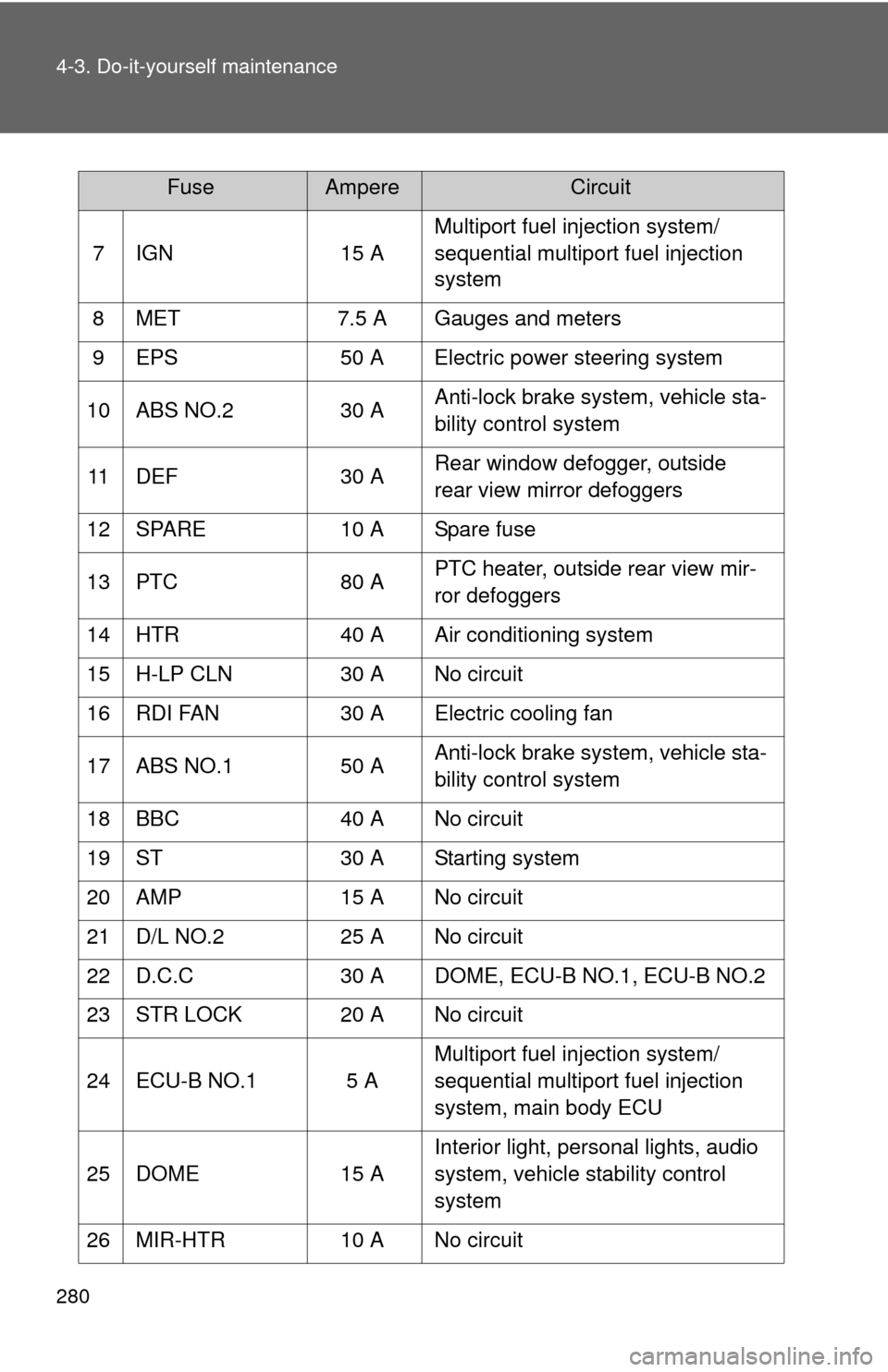
7 IGN15 AMultiport fuel injection system/
sequential multiport fuel injection
system
8 MET 7.5 A Gauges and meters
9 EPS 50 A Electric power steering system
10 ABS NO.2 30 AAnti-lock brake system, vehicle sta-
bility control system
11 DEF 30 ARear window defogger, outside
rear view mirror defoggers
12 SPARE 10 A Spare fuse
13 PTC 80 APTC heater, outside rear view mir-
ror defoggers
14 HTR 40 A Air conditioning system
15 H-LP CLN 30 A No circuit
16 RDI FAN 30 A Electric cooling fan
17 ABS NO.1 50 AAnti-lock brake system, vehicle sta-
bility control system
18 BBC 40 A No circuit
19 ST 30 A Starting system
20 AMP 15 A No circuit
21 D/L NO.2 25 A No circuit
22 D.C.C 30 A DOME, ECU-B NO.1, ECU-B NO.2
23 STR LOCK 20 A No circuit
24 ECU-B NO.1 5 A Multiport fuel injection system/
sequential multiport fuel injection
system, main body ECU
25 DOME 15 AInterior light, personal lights, audio
system, vehicle stability control
system
26 MIR-HTR 10 A No circuit
FuseAmpereCircuit
Page 281 of 400
281
4-3. Do-it-yourself maintenance
4
Maintenance and care
27 ETCS
10 AMultiport fuel injection system/
sequential multiport fuel injection
system
28 HAZ 15 ATurn signal lights, emergency
flashers
29 AM2 7.5 AMultiport fuel injection system/
sequential multiport fuel injection
system, starting system
30 ECU-B NO.2 5 A Gauges and meters, wireless
remote control system, tire pres-
sure warning system, front passen-
ger occupant classification system
31 ALT-S 7.5 A Charging system
32 R/I 50 AEFI MAIN, EFI NO.2, EFI NO.3,
IG2, IGN, MET, HORN
33 SPARE 20 A Spare fuse
34 SPARE 30 A Spare fuse
FuseAmpereCircuit
Page 282 of 400
282 4-3. Do-it-yourself maintenance
Engine compartment (type B fuse box)
*1: NCP131L-AGMRKA, NCP131L-AGPRKA, NCP131L-AHMRKA,
NCP131L-AHPRKA, NCP131L-AGMRKK, NCP131L-AGPRKK,
NCP131L-AHMRKK, NCP131L-AH PRKK, NCP131L-AGMVKK,
NCP131L-AGPVKK, NCP131L-AHMVKK and NCP131L-AHPVKK mod-
els
*2
*2: The model code is indicated on the Certification Label. ( P. 343)
FuseAmpereCircuit
1 EU-DRL 15 A No circuit
2 S-HORN 10 AMultiport fuel injection system/
sequential multiport fuel injection
system
3 H-LP MAIN 7.5 A Headlights
4ST
*140 A No circuit
5 H-LP RH HI 10 A Right-hand headlight (high beam)
6 H-LP LH HI 10 A Left-hand headlight (high beam),
gauges and meters
7 H-LP RH LO 10 A Right-hand headlight (low beam)
8 H-LP LH LO 10 A Left-hand headlight (low beam),
front fog lights
Page 284 of 400
284 4-3. Do-it-yourself maintenance
Under the driver’s side instrument panel
FuseAmpereCircuit
1 TAIL NO.2 10 A Parking lights, tail lights, license
plate lights, side marker lights
2 PANEL 5 A Gauges and meters, instrument
panel lights, switch illumination
3 DOOR R/R 20 A Power windows
4 DOOR P 20 A Power windows
5 ECU-IG NO.1 5 A Electric cooling fan, rear window
defogger, vehicle stability control
system, electric power steering sys-
tem, main body ECU, wireless
remote control system, tire pressure
warning system
6 ECU-IG NO.2 5 A Vehicle stability control system
7 A/C 7.5 AAir conditioning system, rear window
defogger, outside rear view mirror
defoggers
8 GAUGE 10 ABack-up lights, shift lock control sys-
tem, audio system, charging system,
multiport fuel injection system/
sequential multiport fuel injection
system
9 WASHER 15 A Windshield washer
10 WIPER 20 A Windshield wiper
Page 285 of 400

285
4-3. Do-it-yourself maintenance
4
Maintenance and care
11 WIPER RR 15 A Rear window wiper
12 P/W 30 A Power windows
13 DOOR R/L 20 A Power windows
14 DOOR 20 A Power windows
15 CIG 15 A Power outlets
16 ACC 5 AMain body ECU, outside rear view
mirrors, audio system, shift lock con-
trol system
17 D/L 25 APower door lock system, main
body ECU
18 OBD 7.5 A On-board diagnosis system
19 STOP 7.5 AMultiport fuel injection system/
sequential multiport fuel injection
system, vehicle stability control sys-
tem, stop lights, high mounted stop-
light
20 AM1 7.5 A Starting system, engine switch
21 FOG FR 15 A Front fog lights
■ After a fuse is replaced
●If the lights do not turn on even after the fuse has been replaced, a bulb
may need replacement. ( P. 287)
● If the replaced fuse blows again, have the vehicle inspected by your
Toyota dealer.
■ If there is an overload in a circuit
The fuses are designed to blow, protecting the wiring harness from damage.
■ When replacing light bulbs
Toyota recommends that you use genuine Toyota products designed for this
vehicle.
Because certain bulbs are connected to circuits designed to prevent over-
load, non-genuine parts or parts non designed for this vehicle may be unus-
able.
FuseAmpereCircuit
Page 287 of 400
287
4-3. Do-it-yourself maintenance
4
Maintenance and care
Light bulbs
You may replace the following bulbs by yourself. The difficulty level
of replacement varies depending on the bulb. If necessary bulb
replacement seems difficult to perfor m, contact your Toyota dealer.
For more information about replacing other light bulbs, contact your
Toyota dealer.
■ Preparing for light bulb replacement
Check the wattage of the light bulb to be replaced. ( P. 352)
■ Front bulb locations
Headlights and daytime
running lights (if equipped)
Front fog lights
(if equipped)
Front side
marker lights
Front turn signal lights/
parking lights
Page 288 of 400
288 4-3. Do-it-yourself maintenance
Replacing light bulbs■ Headlights and daytime running lights (if equipped)
Unplug the connector.
Remove the rubber cover.
■Rear bulb locations
Back-up lights
Rear turn signal lights
Stop/tail and rear
side marker lights
License plate lights
Page 289 of 400
289
4-3. Do-it-yourself maintenance
4
Maintenance and care
Release the bulb retaining
spring.
Remove the bulb.
To install a new bulb, align the
tabs of the bulb with the cutouts
of the mounting hole.
■
Front fog lights (if equipped)
Remove the screws.
Remove the grommet.