2014 SUBARU TRIBECA odometer
[x] Cancel search: odometerPage 24 of 426
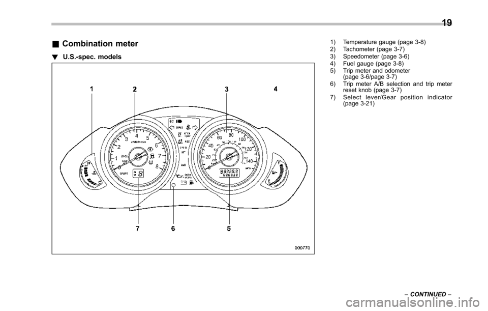
&Combination meter
!U.S.-spec. models
1) Temperature gauge (page 3-8)2) Tachometer (page 3-7)3) Speedometer (page 3-6)4) Fuel gauge (page 3-8)5) Trip meter and odometer(page 3-6/page 3-7)6) Trip meter A/B selection and trip meterreset knob (page 3-7)7) Select lever/Gear position indicator(page 3-21)
19
–CONTINUED–
Page 25 of 426
20
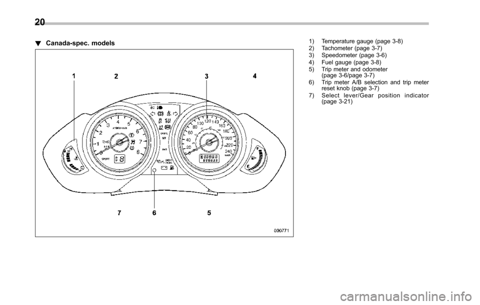
!Canada-spec. models1) Temperature gauge (page 3-8)2) Tachometer (page 3-7)3) Speedometer (page 3-6)4) Fuel gauge (page 3-8)5) Trip meter and odometer(page 3-6/page 3-7)6) Trip meter A/B selection and trip meterreset knob (page 3-7)7) Select lever/Gear position indicator(page 3-21)
Page 26 of 426
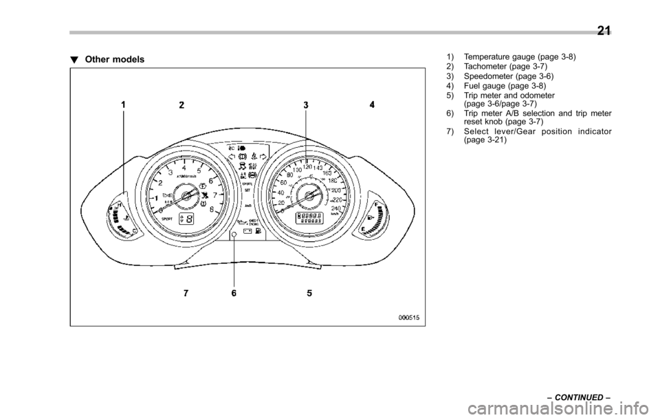
!Other models1) Temperature gauge (page 3-8)2) Tachometer (page 3-7)3) Speedometer (page 3-6)4) Fuel gauge (page 3-8)5) Trip meter and odometer(page 3-6/page 3-7)6) Trip meter A/B selection and trip meterreset knob (page 3-7)7) Select lever/Gear position indicator(page 3-21)
21
–CONTINUED–
Page 121 of 426
2-16Keys and doors
Alarm system
The alarm system helps to protect yourvehicle and valuables from theft. The hornsounds and the turn signal lights flash ifsomeone attempts to break into yourvehicle.
The system can be armed and disarmedwith the remote transmitter.
The system does not operate when thekey is inserted into the ignition switch.
Your vehicle’s alarm system has been setfor activation at the time of shipment fromthe factory. You can set the system fordeactivation yourself or have it done byyour SUBARU dealer.
&System operation
The alarm system will give the followingalarms when triggered.
.The vehicle’s horn will sound for 30seconds.
.The turn signal lights will flash for 30seconds.
If any of the doors or the rear gate remainsopen after the 30-second period, the hornwill continueto sound for a maximum of 3minutes. If any of the doors or the reargate is closed while the horn is sounding,the horn will stop sounding with a delay of
up to 30 seconds.
The alarm is triggered by:
.Opening any of the doors or the reargate
.Physical impact to the vehicle, such asforced entry (only vehicles with shocksensors (dealer option))
NOTE
The alarm system can be set to triggerthe illumination of the following interiorlights.
.Dome light (illuminates only whenthe dome light switch is in the“DOOR”position).Map lights
The notifications regarding the domelight and the map lights are deactivatedas the factory setting. A SUBARUdealer can activate the system. Contactyour SUBARU dealer for details.
&Activating and deactivating
the alarm system
To change the setting of your vehicle’salarm system for activation or deactiva-tion, do the following.
1. Disarm the alarm system. Refer to“Disarming the system”F2-18.
2. Sit in the driver’s seat and shut all
doors and the rear gate.
3. Turn the ignition switch to the“ON”position.
4. Hold down the UNLOCK side of thedriver’s power door locking switch, openthe driver’s door within the following 1second, and wait 10 seconds withoutreleasing the switch. The setting will thenbe changed as follows.
If the system was previously activated:
The odometer/trip meter screen displays“AL oF”and the horn sounds twice,indicating that the system is now deacti-vated.
If the system was previously deacti-vated:
The odometer/trip meter screen displays“AL on”and the horn sounds once,indicating that the system is now acti-vated.
NOTE
Yo u m a y h a v e t h e a b o v e s e t t i n gchange done by your SUBARU dealer.
Page 134 of 426
Ignition switch..................................................... 3-3LOCK.................................................................. 3-3Acc ..................................................................... 3-4ON ...................................................................... 3-4START ................................................................ 3-4Key reminder chime............................................ 3-4Ignition switch light............................................. 3-4
Hazard warning flasher....................................... 3-5
Meters and gauges.............................................. 3-5Combination meter illumination........................... 3-5Canceling the function for meter needle/gaugemovement and combination meter sequentialillumination upon turning on the ignitionswitch............................................................... 3-5Speedometer....................................................... 3-6Odometer............................................................ 3-6Double trip meter................................................ 3-7Tachometer......................................................... 3-7Fuel gauge.......................................................... 3-8Temperature gauge............................................. 3-8
Warning and indicator lights.............................. 3-9Seatbelt warning light and chime........................ 3-10SRS airbag system warning light........................ 3-11Front passenger’s frontal airbag ON and OFFindicators......................................................... 3-12CHECK ENGINE warning light/Malfunctionindicator light................................................... 3-12Charge warning light.......................................... 3-13Oil pressure warning light.................................. 3-13AT OIL TEMP warning light................................. 3-13
Rear differential oil temperature warninglight................................................................ 3-13Low tire pressure warning light.......................... 3-14ABS warning light.............................................. 3-15Brake system warning light................................ 3-16Low fuel warning light....................................... 3-17Door open warning light.................................... 3-17Windshield washer fluid warning light................ 3-17All-Wheel Drive warning light ............................. 3-18Vehicle Dynamics Control warning light (U.S.-spec models and Canada-spec. models)/VehicleDynamics Control operation indicator light (allmodels)........................................................... 3-18Traction Control system OFF indicator light(U.S.-specmodels and Canada-spec.models)........................................................... 3-19Vehicle Dynamics Control warning light (LatinAmerica-spec. models)/Traction Control OFFindicator light (Latin America-spec. models)..... 3-19Security indicator light....................................... 3-21SPORT mode indicator light............................... 3-21Select lever/Gear position indicator.................... 3-21Turn signal indicator lights................................. 3-21High beam indicator light................................... 3-22Cruise control indicator light.............................. 3-22Cruise control set indicator light........................ 3-22Headlight indicator light..................................... 3-22Front fog lightindicator light.............................. 3-22
Clock.................................................................. 3-22
Outside temperature indicator.......................... 3-23Low outside temperature warning...................... 3-24
Instruments and controls
3
Page 138 of 426
Hazard warning flasher
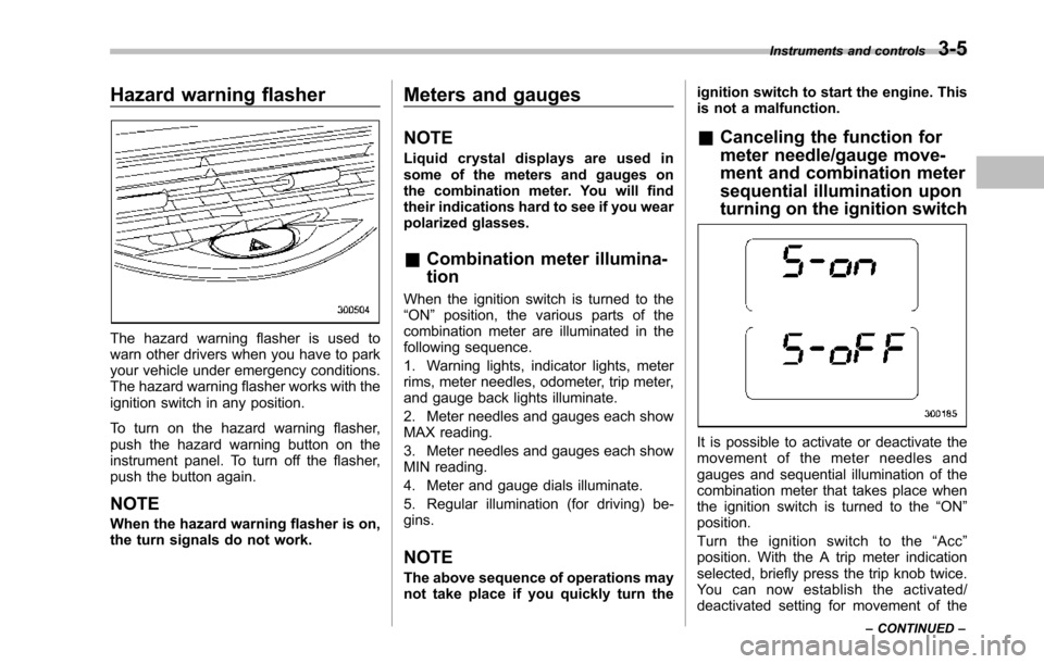
Thehazard warning flasher is used towarn other drivers when you have to parkyour vehicle under emergency conditions.The hazard warning flasher works with theignition switch in any position.
To turn on the hazard warning flasher,push the hazard warning button on theinstrumentpanel. To turn off the flasher,push the button again.
NOTE
When the hazard warning flasher is on,the turn signals do not work.
Meters and gauges
NOTE
Liquid crystal displays are used insome of the meters and gauges onthe combination meter. You will findtheir indications hard to see if you wearpolarized glasses.
&Combination meter illumina-
tion
When the ignition switch is turned to the“ON”position, the various parts of thecombinationmeter are illuminated in thefollowing sequence.
1. Warning lights, indicator lights, meterrims, meter needles, odometer, trip meter,and gauge back lights illuminate.
2. Meter needles and gauges each showMAX reading.
3. Meter needles and gauges each showMIN reading.
4. Meter and gauge dials illuminate.
5. Regular illumination (for driving) be-gins.
NOTE
The above sequence of operations maynot take place if you quickly turn the
ignition switch to start the engine. Thisis not a malfunction.
&Canceling the function for
meter needle/gauge move-
ment and combination meter
sequential illumination upon
turning on the ignition switch
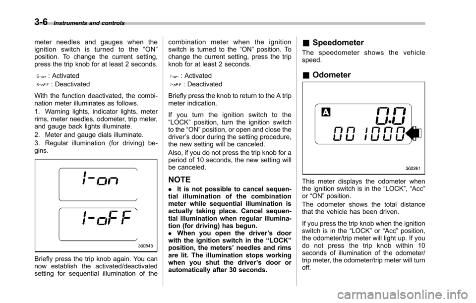
It is possible to activate or deactivate themovement of the meter needles andgauges and sequential illumination of thecombination meter that takes place whenthe ignition switch is turned to the“ON”position.
Turn the ignition switch to the“Acc”position. With the A trip meter indicationselected, briefly press the trip knob twice.Yo u c a n n o w e s t a b l i s h t h e a c t i v a t e d /deactivated setting for movement of the
Instruments and controls3-5
–CONTINUED–
Page 139 of 426
3-6Instruments and controls
meter needles and gauges when theignition switch is turned to the“ON”position. To change the current setting,press the trip knob for at least 2 seconds.
: Activated
: Deactivated
With the function deactivated, the combi-nation meter illuminates as follows.
1. Warning lights, indicator lights, meterrims, meter needles, odometer, trip meter,and gauge back lights illuminate.
2. Meter and gauge dials illuminate.
3. Regular illumination (for driving) be-gins.
Briefly press the trip knob again. You cannow establish the activated/deactivatedsetting for sequential illumination of the
combination meter when the ignitionswitch is turned to the“ON”position. Tochange the current setting, press the tripknob for at least 2 seconds.
: Activated
: Deactivated
Briefly press the knob to return to the A tripmeter indication.
If you turn the ignition switch to the“LOCK”position, turn the ignition switchto the“ON”position, or open and close thedriver’s door during the setting procedure,the new setting will be canceled.
Also, if you do not press the trip knob for aperiod of 10 seconds, the new setting willbe canceled.
NOTE
.It is not possible to cancel sequen-tial illumination of the combinationmeter while sequential illumination isactually taking place. Cancel sequen-tial illumination when regular illumina-tion (for driving) has begun..When you open the driver’s doorwith the ignition switch in the“LOCK”position, the meters’needles and rimsare lit. The illumination stops workingwhen you shut the driver’s door orautomatically after 30 seconds.
&Speedometer
The speedometer shows the vehiclespeed.
&Odometer
This meter displays the odometer whenthe ignition switch is in the“LOCK”,“Acc”or“ON”position.
The odometer shows the total distancethatthe vehicle has been driven.
If you press the trip knob when the ignitionswitch is in the“LOCK”or“Acc”position,the odometer/trip meter will light up. If youdo not press the trip knob within 10seconds of illumination of the odometer/trip meter, the odometer/trip meter will turnoff.
Page 140 of 426
The odometer/trip meter will also turn off ifyou open and close the driver’sdoorwithin 10 seconds of illumination of theodometer/trip meter.
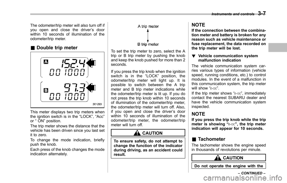
&Double trip meter
This meter displays two trip meters whenthe ignition switch is in the“LOCK”,“Acc”or“ON”position.
The trip metershows the distance that thevehicle has been driven since you last setit to zero.
To change the mode indication, brieflypush the knob.
Each press of the knob changes the modeindication alternately.
To set the trip meter to zero, select the Atrip or B trip meter by pushing the knoband keep the knob pushed for more than 2seconds.
If you press the trip knob when the ignitionswitch is in the“LOCK”position, theodometer/trip meter will light up. It ispossible to switch between the A tripmeter and B trip meter indications whilethe odometer/trip meter is lit up. If you donot press the trip knob within 10 secondsof illumination of the odometer/trip meter,the odometer/trip meter will turn off. Also,if you open and close the driver’s doorwithin 10 seconds of illumination of theodometer/trip meter, the odometer/tripmeter will turn off.
CAUTION
To ensure safety, do not attempt tochange thefunction of the indicatorduring driving, as an accident couldresult.
NOTE
If the connection between the combina-tion meter and battery is broken for anyreason such as vehicle maintenance orfuse replacement, the data recorded onthe trip meter will be lost.
!Vehicle communication systemmalfunction indication
The vehicle communication system car-ries various types of information (vehiclespeed, running conditions, etc.) to controlmodules. In the event of a malfunction inthis communication system, the trip meterwill show“”.
If the trip meter shows“”, immediatelycontact the nearest SUBARU dealer andhavethe vehicle communication systeminspected.
NOTE
If you press the trip knob while the tripmeter is showing“”, the trip meterindication will appear for 10 seconds.
&Tachometer
The tachometer shows the engine speedin thousands of revolutions per minute.
CAUTION
Do not operate the engine with the
Instruments and controls3-7
–CONTINUED–