2014 SUBARU IMPREZA WRX wheel torque
[x] Cancel search: wheel torquePage 262 of 414
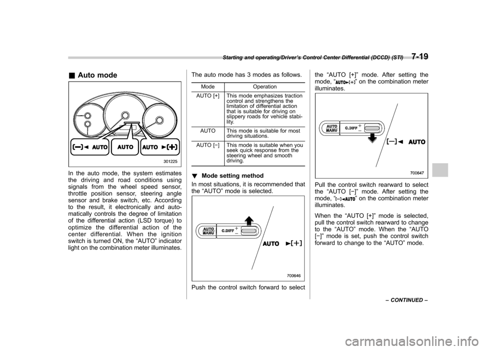
&Auto mode
In the auto mode, the system estimates
the driving and road conditions using
signals from the wheel speed sensor,
throttle position sensor, steering angle
sensor and brake switch, etc. According
to the result, it electronically and auto-
matically controls the degree of limitation
of the differential action (LSD torque) to
optimize the differential action of the
center differential. When the ignition
switch is turned ON, the “AUTO ”indicator
light on the combination meter illuminates. The auto mode has 3 modes as follows.
Mode Operation
AUTO [+] This mode emphasizes traction control and strengthens the
limitation of differential action
that is suitable for driving on
slippery roads for vehicle stabi-
lity.
AUTO This mode is suitable for most driving situations.
AUTO [ �] This mode is suitable when you
seek quick response from the
steering wheel and smooth driving.
! Mode setting method
In most situations, it is recommended that the “AUTO ”mode is selected.
Push the control switch forward to select the
“AUTO [+] ”mode. After setting the
mode, “
”on the combination meter
illuminates.
Pull the control switch rearward to select the “AUTO [ �]” mode. After setting the
mode, “
”on the combination meter
illuminates.
When the “AUTO [+] ”mode is selected,
pull the control switch rearward to change
to the “AUTO ”mode. When the “AUTO
[ � ]” mode is set, push the control switch
forward to change to the “AUTO ”mode.
Starting and operating/Driver ’s Control Center Differential (DCCD) (STI)7-19
– CONTINUED –
Page 264 of 414
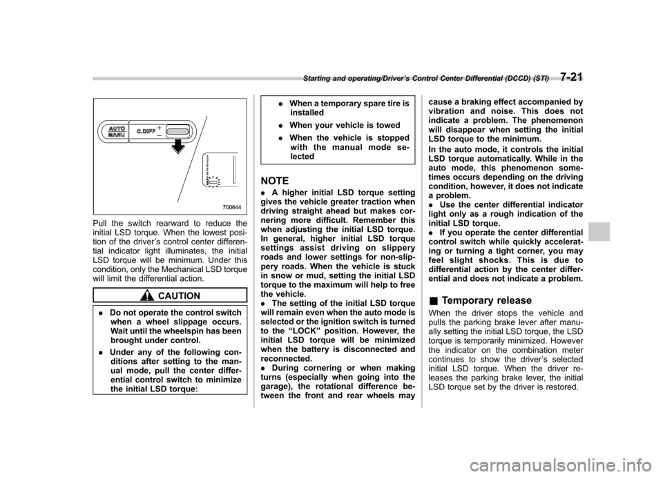
Pull the switch rearward to reduce the
initial LSD torque. When the lowest posi-
tion of the driver’s control center differen-
tial indicator light illuminates, the initial
LSD torque will be minimum. Under this
condition, only the Mechanical LSD torque
will limit the differential action.
CAUTION
. Do not operate the control switch
when a wheel slippage occurs.
Wait until the wheelspin has been
brought under control.
. Under any of the following con-
ditions after setting to the man-
ual mode, pull the center differ-
ential control switch to minimize
the initial LSD torque: .
When a temporary spare tire is
installed
. When your vehicle is towed
. When the vehicle is stopped
with the manual mode se-lected
NOTE . A higher initial LSD torque setting
gives the vehicle greater traction when
driving straight ahead but makes cor-
nering more difficult. Remember this
when adjusting the initial LSD torque.
In general, higher initial LSD torque
settings assist driving on slippery
roads and lower settings for non-slip-
pery roads. When the vehicle is stuck
in snow or mud, setting the initial LSD
torque to the maximum will help to free
the vehicle.. The setting of the initial LSD torque
will remain even when the auto mode is
selected or the ignition switch is turned
to the “LOCK ”position. However, the
initial LSD torque will be minimized
when the battery is disconnected andreconnected.. During cornering or when making
turns (especially when going into the
garage), the rotational difference be-
tween the front and rear wheels may cause a braking effect accompanied by
vibration and noise. This does not
indicate a problem. The phenomenon
will disappear when setting the initial
LSD torque to the minimum.
In the auto mode, it controls the initial
LSD torque automatically. While in the
auto mode, this phenomenon some-
times occurs depending on the driving
condition, however, it does not indicate
a problem..
Use the center differential indicator
light only as a rough indication of the
initial LSD torque.. If you operate the center differential
control switch while quickly accelerat-
ing or turning a tight corner, you may
feel slight shocks. This is due to
differential action by the center differ-
ential and does not indicate a problem. & Temporary release
When the driver stops the vehicle and
pulls the parking brake lever after manu-
ally setting the initial LSD torque, the LSD
torque is temporarily minimized. However
the indicator on the combination meter
continues to show the driver ’s selected
initial LSD torque. When the driver re-
leases the parking brake lever, the initial
LSD torque set by the driver is restored.
Starting and operating/Driver ’s Control Center Differential (DCCD) (STI)7-21
Page 304 of 414
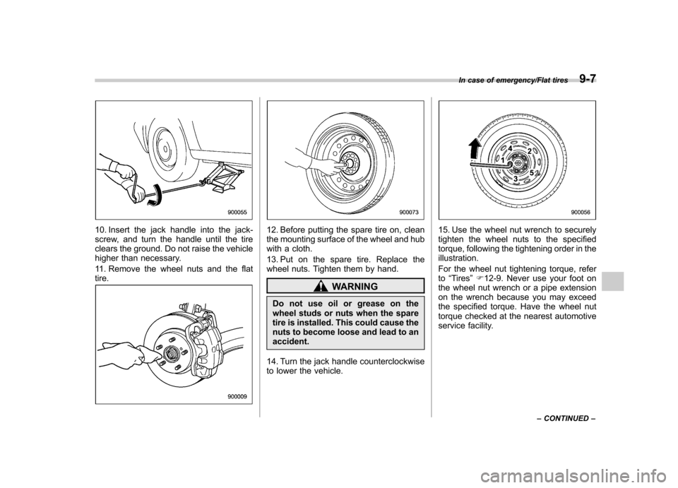
10. Insert the jack handle into the jack-
screw, and turn the handle until the tire
clears the ground. Do not raise the vehicle
higher than necessary.
11. Remove the wheel nuts and the flat tire.12. Before putting the spare tire on, clean
the mounting surface of the wheel and hub
with a cloth.
13. Put on the spare tire. Replace the
wheel nuts. Tighten them by hand.
WARNING
Do not use oil or grease on the
wheel studs or nuts when the spare
tire is installed. This could cause the
nuts to become loose and lead to anaccident.
14. Turn the jack handle counterclockwise
to lower the vehicle.
15. Use the wheel nut wrench to securely
tighten the wheel nuts to the specified
torque, following the tightening order in theillustration.
For the wheel nut tightening torque, refer to “Tires ”F 12-9. Never use your foot on
the wheel nut wrench or a pipe extension
on the wrench because you may exceed
the specified torque. Have the wheel nut
torque checked at the nearest automotive
service facility.
In case of emergency/Flat tires9-7
– CONTINUED –
Page 349 of 414
11-30Maintenance and service/Tires and wheels
Using tires of a non-specified size detracts
from controllability, ride comfort, braking
performance, speedometer accuracy and
odometer accuracy. It also creates incor-
rect body-to-tire clearances and inappro-
priately changes the vehicle’sground
clearance.
All four tires must be the same in terms of
size, circumference, speed symbol, load
index, construction, manufacturer, brand
(tread pattern), and degrees of wear. You
are advised to replace the tires with new
ones that are identical to those fitted as
standard equipment.
For safe vehicle operation, SUBARU
recommends replacing all four tires at
the same time.
WARNING
. When you replacing or installing
tire(s), all four tires must be the
same for following items.
(a) Size
(b) Circumference
(c) Speed symbol
(d) Load index
(e) Construction
(f) Manufacturer
(g) Brand (tread pattern) (h) Degrees of wear
For the items (a) to (d), you must
obey the specification that is
printed on the tire placard. The
tire placard is located on the
bottom of driver
’s door pillar.
If all of four tires are not the same
for items (a) to (h), there is a
possibility that serious mechan-
ical damage could occur to the
drive train of your car, and affect
the following. — Ride
— Handling
— Braking
— Speedometer/Odometer
calibration— Clearance between the body
and tires
It also may be dangerous and
lead to loss of vehicle control,
and it can lead to an accident.
. Use only radial tires. Do not use
radial tires together with belted
bias tires and/or bias-ply tires.
Doing so can dangerously re-
duce controllability, resulting in
an accident. &
Wheel replacement
When replacing wheels due, for example,
to damage, make sure the replacement
wheels match the specifications of the
wheels that are fitted as standard equip-
ment. Replacement wheels are available
from SUBARU dealers.
WARNING
Use only those wheels that are
specified for your vehicle. Wheels
not meeting specifications could
interfere with brake caliper opera-
tion and may cause the tires to rub
against the wheel well housing dur-
ing turns. The resulting loss of
vehicle control could lead to anaccident.
NOTE
When any of the wheels are removed
and replaced for tire rotation or to
change a flat tire, always check the
tightness of the wheel nuts after driv-
ing approximately 600 miles (1,000 km).
If any nut is loose, tighten it to the
specified torque.
Page 350 of 414
Aluminum wheels
Aluminum wheels can be scratched and
damaged easily. Handle them carefully to
maintain their appearance, performance,
and safety. .When any of the wheels are removed
and replaced for tire rotation or to change
a flat tire, always check the tightness of
the wheel nuts after driving approximately
600 miles (1,000 km). If any nut is loose,
tighten it to the specified torque. . Never apply oil to the threaded parts,
wheel nuts, or tapered surface of the wheel. . Never let the wheel rub against sharp
protrusions or curbs.. When wheel nuts, balance weights, or
the center cap is replaced, be sure to
replace them with genuine SUBARU parts
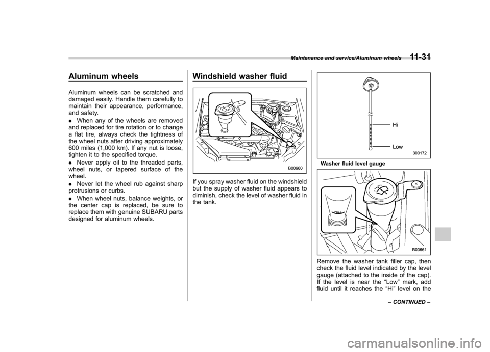
designed for aluminum wheels. Windshield washer fluid
If you spray washer fluid on the windshield
but the supply of washer fluid appears to
diminish, check the level of washer fluid in
the tank.
Washer fluid level gauge
Remove the washer tank filler cap, then
check the fluid level indicated by the level
gauge (attached to the inside of the cap).
If the level is near the
“Low ”mark, add
fluid until it reaches the “Hi ”level on the
Maintenance and service/Aluminum wheels11-31
– CONTINUED –
Page 376 of 414
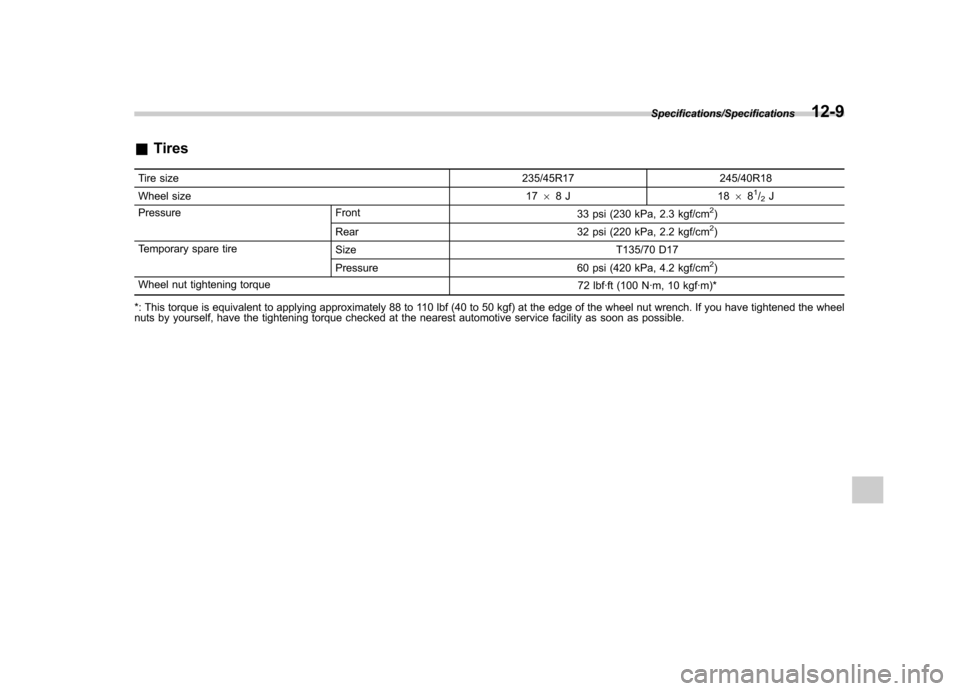
&Tires
Tire size 235/45R17 245/40R18
Wheel size 1768J 18 68
1/2J
Pressure Front 33 psi (230 kPa, 2.3 kgf/cm2)
Rear 32 psi (220 kPa, 2.2 kgf/cm2)
Temporary spare tire Size T135/70 D17
Pressure 60 psi (420 kPa, 4.2 kgf/cm
2)
Wheel nut tightening torque 72 lbf·ft (100 N·m, 10 kgf·m)*
*: This torque is equivalent to applying approximately 88 to 110 lbf (40 to 50 kgf) at the edge of the wheel nut wrench. If you have tightened the wheel
nuts by yourself, have the tightening torque checked at the nearest automotive service facility as soon as possible.
Specifications/Specifications12-9
Page 395 of 414
13-10Consumer information and Reporting safety defects/Tire information
&Tire care –maintenance and
safety practices
. Check on a daily basis that the
tires are free from serious damage,
nails, and stones. At the same time,
check the tires for abnormal wear. . Inspect the tire tread regularly
and replace the tires before their
tread wear indicators become visi-
ble. When a tire ’streadwear
indicator becomes visible, the tire
is worn beyond the acceptable limit
and must be replaced immediately.
With a tire in this condition, driving
at even low speeds in wet weather
can cause the vehicle to hydro-
plane. Possible resulting loss of
vehiclecontrolcanleadtoanaccident. . To maximize the life of each tire
and ensure that the tires wear
uniformly, it is best to rotate the
tires every 7,500 miles (12,000 km).
For information about the tire rota-
tion order, refer to “Tire rotation ”
F 11-29 .
Replace any damaged or
unevenly worn tires at the time of rotation. After tire rotation, adjust
the tire pressures and make sure
the wheel nuts are correctly tigh-
tened. For information about the
tightening torque and tightening
sequence for the wheel nuts, refer to
“Flat tires ”F 9-5 .
& Vehicle load limit –how to
determine
The load capacity of your vehicle is
determined by weight, not by avail-
able cargo space. The load limit of
your vehicle is shown on the
vehicle placard attached to the
driver ’s side B-pillar. Locate the
statement “The combined weight
of occupants and cargo should
never exceed XXX kg or XXX lbs ”
on your vehicle ’s placard.
Thevehicleplacardalsoshows
seating capacity of your vehicle.
The total load capacity includes the
total weight of driver and all pas-
sengers and their belongings, any
cargo, any optional equipment such
as a trailer hitch, roof rack or bike carrier, etc., and the tongue load of
a trailer. Therefore cargo capacity
can be calculated by the following method.
Cargo capacity = Load limit
�(total
weight of occupants + total weight
of optional equipment + tongue
load of a trailer (if applicable))
For information about vehicle load-
ing, refer to “Loading your vehicle ”
F 8-10 .
NOTE
Your vehicle is neither designed
nor intended to be used for
trailer towing. Therefore, never
tow a trailer with your vehicle.
Page 412 of 414

Waxing and polishing................................................. 10-3
Wear indicators ......................................................... 11-28
Wheel
Aluminum ............................................................. 11-31
Balance ............................................................... 11-28
Nut tightening torque ........................................ 9-5, 12-9
Replacement ........................................................ 11-30
Windows ................................................................... 2-20
Windshield
Washer fluid ......................................................... 11-31
Wiper and washer switches ..................................... 3-36
Wiper blades ........................................................ 11-33
Wiper deicer .......................................................... 3-47
Winter Driving .................................................................... 8-6
Tires ............................................................. 8-8, 11-24
Wiper and washer ...................................................... 3-34
Wiper deicer .............................................................. 3-47 Index
14-11