Page 263 of 414

7-20Starting and operating/Driver’s Control Center Differential (DCCD) (STI)
& Manual mode
In the manual mode, you can use the
center differential control switch to adjust
the initial LSD torque as desired. When
this mode is selected, the “AUTO ”indica-
tor light on the combination meter turns
off. !
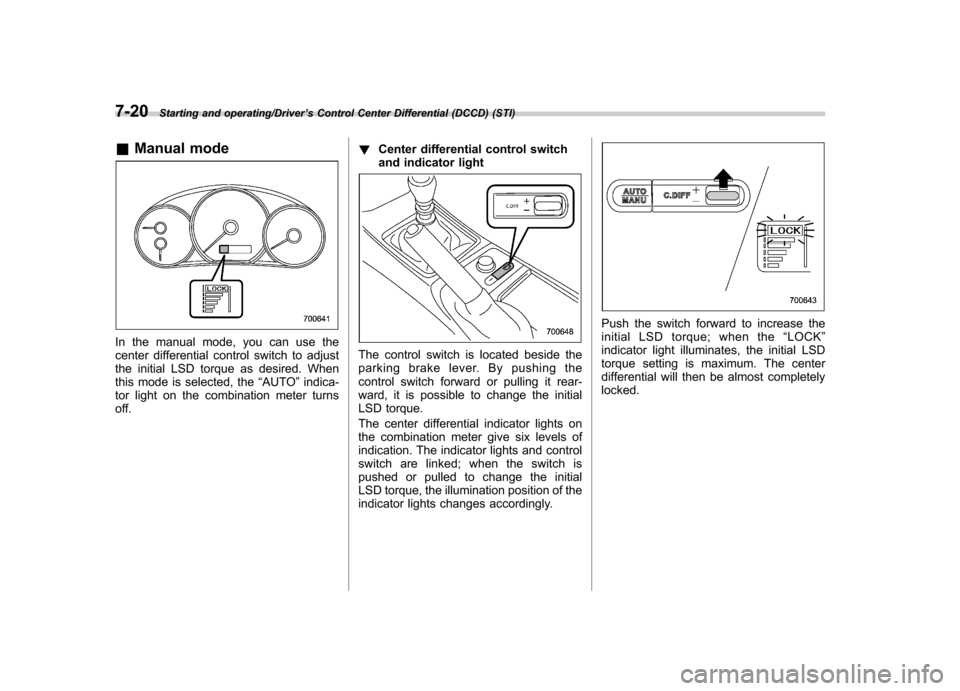
Center differential control switch
and indicator lightThe control switch is located beside the
parking brake lever. By pushing the
control switch forward or pulling it rear-
ward, it is possible to change the initial
LSD torque.
The center differential indicator lights on
the combination meter give six levels of
indication. The indicator lights and control
switch are linked; when the switch is
pushed or pulled to change the initial
LSD torque, the illumination position of the
indicator lights changes accordingly.
Push the switch forward to increase the
initial LSD torque; when the “LOCK ”
indicator light illuminates, the initial LSD
torque setting is maximum. The center
differential will then be almost completelylocked.
Page 270 of 414

Electronic Brake Force Dis-
tribution (EBD) system
The EBD system maximizes the effective-
ness of the brakes by allowing the rear
brakes to supply a greater proportion of
the braking force. It functions by adjusting
the distribution of braking force to the rear
wheels in accordance with the vehicle’s
loading condition and speed.
The EBD system is an integral part of the
ABS system and uses some of the ABSsystem ’s components to perform its func-
tion of optimizing the distribution of brak-
ing force. If any of the ABS components
used by the EBD system malfunction, the
EBD system also stops working.
When the EBD system is operating, you
may hear a chattering noise or feel a slight
vibration in the brake pedal. This is normal
and does not indicate a malfunction. &
Steps to take if EBD system malfunctions
If a malfunction occurs in the EBD system,
the system stops working and the brake
system warning light and ABS warning
light illuminate simultaneously.
The EBD system may be malfunctioning if
the brake system warning light and ABS
warning light illuminate simultaneously
during driving.
Even if the EBD system malfunctions, the
conventional braking system will still func-
tion. However, the rear wheels will be
more prone to locking when the brakes
are applied harder than usual and thevehicle ’s motion may therefore become
somewhat harder to control.
If the brake system warning light and ABS warning light illuminate simultaneously,
take the following steps.
1. Stop the vehicle in the nearest safe,
flat location.
2. Shut down the engine, apply the
parking brake, and then restart it.
3. Release the parking brake. If both
warning lights turn off, the EBD system
may be malfunctioning. Drive carefully to
the nearest SUBARU dealer and have the
system inspected.
4. If both warning lights illuminate again
and remain illuminated after the engine
has been restarted, shut down the engine
again, apply the parking brake, and check
the brake fluid level. Refer to
“Brake fluid ”
F 11-18.
5. If the brake fluid level is not below the“ MIN ”mark, the EBD system may be
malfunctioning. Drive carefully to the
nearest SUBARU dealer and have the
system inspected.
6. If the brake fluid level is below the “ MIN ”mark, DO NOT drive the vehicle.
Instead, have the vehicle towed to the
nearest SUBARU dealer for repair.
WARNING
. Driving with the brake system
warning light illuminated is dan-
Starting and operating/Electronic Brake Force Distribution (EBD) system7-27
– CONTINUED –
Page 307 of 414
9-10In case of emergency/Jump starting
&How to jump start
1. Make sure the booster battery is 12
volts and the negative terminal isgrounded.
2. If the booster battery is in another
vehicle, do not let the two vehicles touch.
3. Turn off all unnecessary lights and accessories.
4. Connect the jumper cables exactly in
the sequence illustrated.
Page 321 of 414

Maintenance and serviceTire replacement .............................................. 11-29
Wheel replacement ........................................... 11-30
Aluminum wheels ............................................. 11-31
Windshield washer fluid .................................. 11-31
Replacement of wiper blades .......................... 11-32
Windshield wiper blade assembly ..................... 11-33
Windshield wiper blade rubber (type A and type B) .................................................................. 11-34
Rear window wiper blade assembly (5-door models). ......................................................... 11-35
Rear window wiper blade rubber (5-door models). ......................................................... 11-35
Battery. .............................................................. 11-37
Fuses ................................................................ 11-38 Installation of accessories
.............................. 11-39
Replacing bulbs ............................................... 11-39
Headlights (models with HID headlights) ........... 11-39
Headlights (models without HID headlights) ...... 11-40
Front turn signal light ...................................... 11-42
Front fog light (if equipped) .............................. 11-42
Rear combination lights ................................... 11-43
Backup light (5-door) ....................................... 11-45
License plate light ........................................... 11-46
Map light ......................................................... 11-46
Dome light and cargo area light ....................... 11-47
Trunk light ....................................................... 11-47
High-mounted stop light (4-door) ... ................... 11-48
Other bulbs ..................................................... 11-48
Page 357 of 414
11-38Maintenance and service/Fuses
Fuses
CAUTION
Never replace a fuse with one hav-
ing a higher rating or with material
other than a fuse because serious
damage or a fire could result.
The fuses are designed to melt during an
overload to prevent damage to the wiring
harness and electrical equipment. The
fuses are located in two fuse boxes.
One is located under the instrument panel
behind the fuse box cover on the driver ’s
seat side. To remove the cover, pull it out.
The other one (main fuse box) is housed
in the engine compartment.
The spare fuses are stored in the main
fuse box cover in the engine compart-ment.
The fuse puller is stored in the main fuse
box in the engine compartment.
1) Good
2) Blown
If any lights, accessories or other electrical
controls do not operate, inspect the
Page 358 of 414

corresponding fuse. If a fuse has blown,
replace it.
1. Turn the ignition switch to the“LOCK ”
position and turn off all electrical acces- sories.
2. Remove the cover.
3. Determine which fuse may be blown.
Look at the back side of each fuse box
cover and refer to “Fuses and circuits ”
F 12-10.
4. Pull out the fuse with the fuse puller.
5. Inspect the fuse. If it has blown,
replace it with a spare fuse of the samerating.
6. If the same fuse blows again, this
indicates that its system has a problem.
Contact your SUBARU dealer for repairs. Installation of accessories
Always consult your SUBARU dealer
before installing fog lights or any other
electrical equipment in your vehicle. Such
accessories may cause the electronic
system to malfunction if they are incor-
rectly installed or if they are not suited for
the vehicle.
Replacing bulbs
WARNING
Bulbs may become very hot while
illuminated. Before replacing bulbs,
turn off the lights and wait until the
bulbs cool down. Otherwise, there is
a risk of sustaining a burn injury.
CAUTION
Replace any bulb only with a new
bulb of the specified wattage. Using
a bulb of different wattage could
result in a fire. For the specified
wattage of each bulb, refer to “Bulb
chart ”F 12-14.
& Headlights (models with HID headlights)
WARNING
High-intensity-discharge (HID) bulbs
are used for the low beams of the
headlights. These HID bulbs use an
extremely high voltage. To avoid the
risk of an electric shock that could
result in serious injury, observe the
Maintenance and service/Installation of accessories11-39
– CONTINUED –
Page 359 of 414

11-40Maintenance and service/Replacing bulbs
following precautions. .Do not replace any headlight
bulbs (both low beam and high
beam) by yourself.
. Do not remove/restore the head-
light assemblies by yourself.
. Do not remove any headlight-
assembly components by your-self.
For replacement, contact your
SUBARU dealer.
& Headlights (models without
HID headlights)
CAUTION
Halogen headlight bulbs become
very hot while in use. If you touch
the bulb surface with bare hands or
greasy gloves, fingerprints or
grease on the bulb surface will
develop into hot spots, causing the
bulb to break. If there are finger
prints or grease on the bulb surface,
wipe them away with a soft cloth
moistened with alcohol. NOTE .
If headlight aiming is required, con-
sult your SUBARU dealer for proper
adjustment of the headlight aim.. It may be difficult to replace the
bulbs. Have the bulbs replaced by your
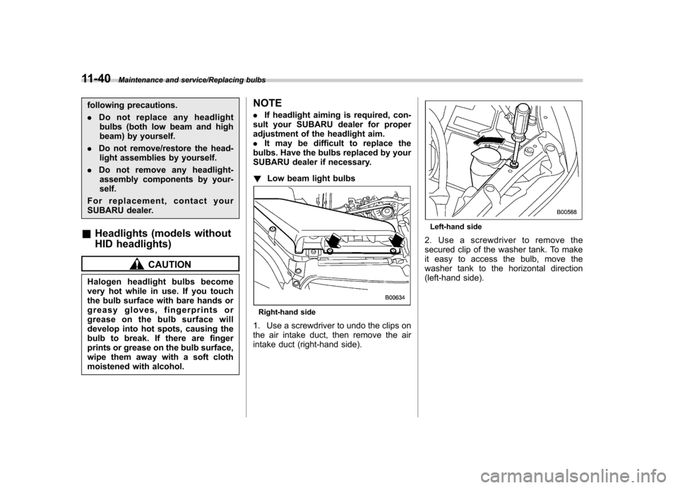
SUBARU dealer if necessary. ! Low beam light bulbs
Right-hand side
1. Use a screwdriver to undo the clips on
the air intake duct, then remove the air
intake duct (right-hand side).
Left-hand side
2. Use a screwdriver to remove the
secured clip of the washer tank. To make
it easy to access the bulb, move the
washer tank to the horizontal direction
(left-hand side).
Page 362 of 414
Type B
1. Remove the clips.
2. Turn over the mud guard.
3. Disconnect the electrical connector.
1) View from driver ’s left-hand side
2) View from driver ’s right-hand side
4. Remove the bulb.
5. Replace the bulb with a new one.
6. After replacing the bulb, reattach the
mud guard. &
Rear combination lights
! 4-door models
1. Remove the clip from the rear trunk
trim with a screwdriver.
2. Open the rear portion of the side trunk
trim panel.
Maintenance and service/Replacing bulbs11-43
– CONTINUED –