2014 SUBARU IMPREZA WRX check engine
[x] Cancel search: check enginePage 135 of 414
3-20Instruments and controls/Warning and indicator lights
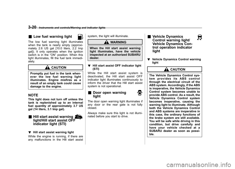
&Low fuel warning light
The low fuel warning light illuminates
when the tank is nearly empty (approxi-
mately 2.6 US gal [10.0 liters, 2.2 Imp
gal]). It only operates when the ignition
switch is in the “ON ”position. When this
light illuminates, fill the fuel tank immedi-
ately.
CAUTION
Promptly put fuel in the tank when-
ever the low fuel warning light
illuminates. Engine misfires as a
result of an empty tank could cause
damage to the engine.
NOTE
This light does not turn off unless the
tank is replenished up to an internal
fuel quantity of approximately 3.7 US
gal (14 liters, 3.1 Imp gal). & Hill start assist warning
light/Hill start assist OFF
indicator light (STI)
!Hill start assist warning light
While the engine is running, if there are
any malfunctions in the Hill start assist system, the light will illuminate.
WARNING
When the Hill start assist warning
light illuminates, have the vehicle
inspected at an authorized SUBARU
dealer.
! Hill start assist OFF indicator light(STI)
While the Hill start assist system is
deactivated, the Hill start assist OFF
indicator light illuminates continuously to
inform the driver that the Hill start assist
system is not operational. & Door open warning light
The door open warning light illuminates if
any door or the rear gate is not fullyclosed.
Always make sure this light is not illumi-
nated before you start to drive. &
Vehicle Dynamics
Control warning light/
Vehicle Dynamics Con-
trol operation indicatorlight
!Vehicle Dynamics Control warning light
CAUTION
The Vehicle Dynamics Control sys-
tem provides its ABS control
through the electrical circuit of the
ABS system. Accordingly, if the ABS
is inoperative, the Vehicle Dynamics
Control system becomes unable to
provide ABS control. As a result, the
Vehicle Dynamics Control system
becomes inoperative, causing the
warning light to illuminate. Although
both the Vehicle Dynamics Control
and ABS systems are inoperative in
this case, the ordinary functions of
the brake system are still available.
You will be safe while driving in this
condition, but drive carefully and
have your vehicle checked at a
SUBARU dealer as soon as possi-ble.
Page 136 of 414
NOTE .If the electrical circuit of the Vehicle
Dynamics Control system itself mal-
functions, only this particular warning
light illuminates. Under these circum-
stances, the ABS (Anti-lock Brake
System) remains fully operational.. The warning light illuminates when
the electronic control system of the
ABS/Vehicle Dynamics Control systemmalfunctions.
The Vehicle Dynamics Control system is
probably inoperative under any of the
following conditions. Have your vehicle
checked at a SUBARU dealer immedi-
ately. . The warning light does not illuminate
when the ignition switch is turned to the “ ON ”position.
. The warning light illuminates while the
vehicle is running.
NOTE
If the warning light behavior is as
described in the following examples,
the Vehicle Dynamics Control system
may be considered to be operating
normally. . The warning light illuminates right
after the engine is started but turns off
immediately and remains off.. The warning light illuminates after the engine has started and turns off
while the vehicle is subsequently beingdriven..
The warning light illuminates during
driving, but turns off immediately and
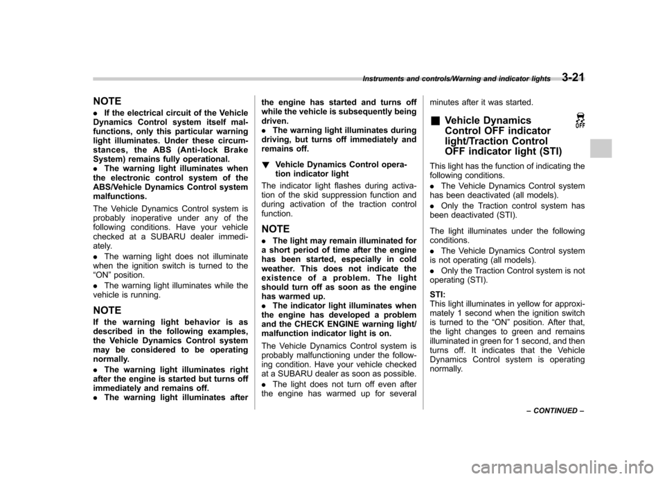
remains off. ! Vehicle Dynamics Control opera-
tion indicator light
The indicator light flashes during activa-
tion of the skid suppression function and
during activation of the traction controlfunction. NOTE . The light may remain illuminated for
a short period of time after the engine
has been started, especially in cold
weather. This does not indicate the
existence of a problem. The light
should turn off as soon as the engine
has warmed up.. The indicator light illuminates when
the engine has developed a problem
and the CHECK ENGINE warning light/
malfunction indicator light is on.
The Vehicle Dynamics Control system is
probably malfunctioning under the follow-
ing condition. Have your vehicle checked
at a SUBARU dealer as soon as possible. . The light does not turn off even after
the engine has warmed up for several minutes after it was started. &
Vehicle Dynamics
Control OFF indicator
light/Traction Control
OFF indicator light (STI)
This light has the function of indicating the
following conditions. .The Vehicle Dynamics Control system
has been deactivated (all models).. Only the Traction control system has
been deactivated (STI).
The light illuminates under the following conditions. . The Vehicle Dynamics Control system
is not operating (all models).. Only the Traction Control system is not
operating (STI). STI:
This light illuminates in yellow for approxi-
mately 1 second when the ignition switch
is turned to the “ON ”position. After that,
the light changes to green and remains
illuminated in green for 1 second, and then
turns off. It indicates that the Vehicle
Dynamics Control system is operating
normally.
Instruments and controls/Warning and indicator lights3-21
– CONTINUED –
Page 137 of 414
3-22Instruments and controls/Warning and indicator lights
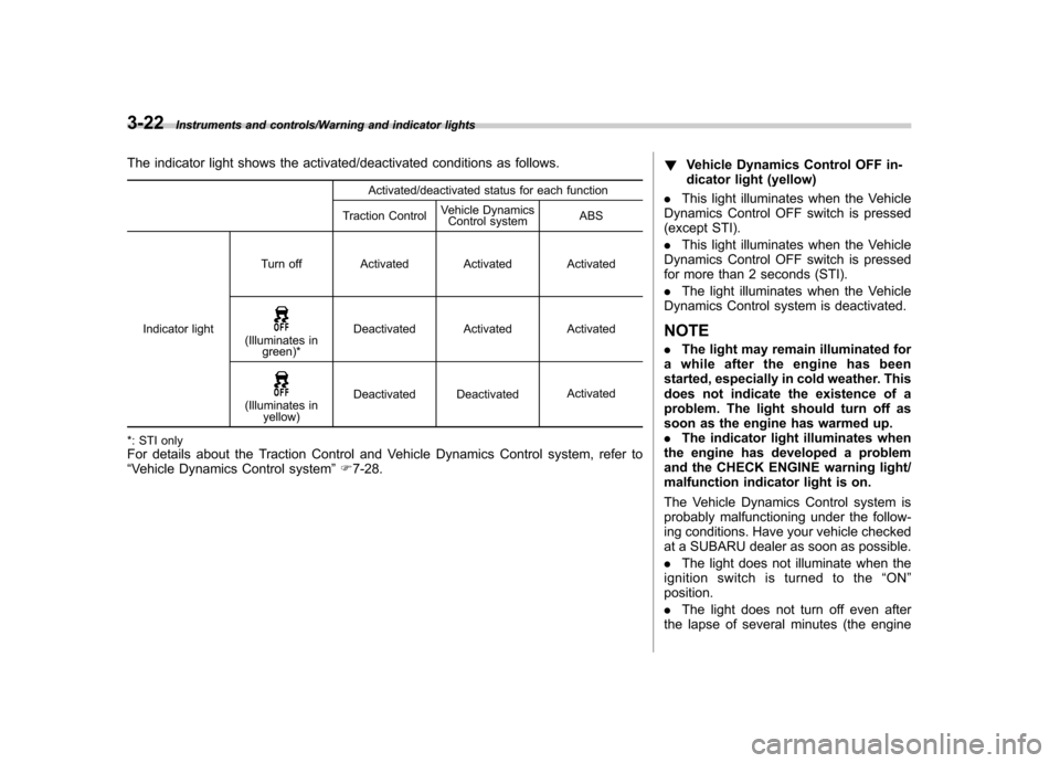
The indicator light shows the activated/deactivated conditions as follows.Activated/deactivated status for each function
Traction Control Vehicle Dynamics
Control system ABS
Indicator light Turn off Activated Activated Activated
(Illuminates in
green)* Deactivated Activated Activated
(Illuminates in
yellow) Deactivated Deactivated
Activated
*: STI only For details about the Traction Control and Vehicle Dynamics Control system, refer to “ Vehicle Dynamics Control system ”F 7-28. !
Vehicle Dynamics Control OFF in-
dicator light (yellow)
. This light illuminates when the Vehicle
Dynamics Control OFF switch is pressed
(except STI). . This light illuminates when the Vehicle
Dynamics Control OFF switch is pressed
for more than 2 seconds (STI). . The light illuminates when the Vehicle
Dynamics Control system is deactivated.
NOTE . The light may remain illuminated for
a while after the engine has been
started, especially in cold weather. This
does not indicate the existence of a
problem. The light should turn off as
soon as the engine has warmed up.. The indicator light illuminates when
the engine has developed a problem
and the CHECK ENGINE warning light/
malfunction indicator light is on.
The Vehicle Dynamics Control system is
probably malfunctioning under the follow-
ing conditions. Have your vehicle checked
at a SUBARU dealer as soon as possible. . The light does not illuminate when the
ignition switch is turned to the “ON ”
position.. The light does not turn off even after
the lapse of several minutes (the engine
Page 139 of 414
3-24Instruments and controls/Warning and indicator lights
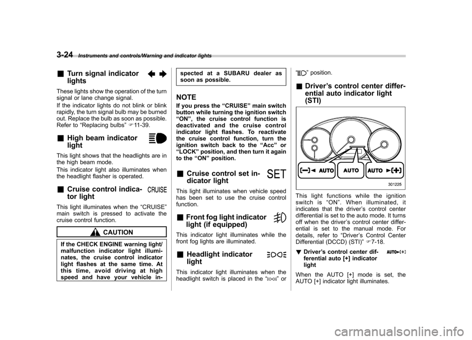
&Turn signal indicator lights
These lights show the operation of the turn
signal or lane change signal.
If the indicator lights do not blink or blink
rapidly, the turn signal bulb may be burned
out. Replace the bulb as soon as possible.
Refer to “Replacing bulbs ”F 11-39.
& High beam indicator light
This light shows that the headlights are in
the high beam mode.
This indicator light also illuminates when
the headlight flasher is operated. &Cruise control indica-
tor light
This light illuminates when the “CRUISE ”
main switch is pressed to activate the
cruise control function.
CAUTION
If the CHECK ENGINE warning light/
malfunction indicator light illumi-
nates, the cruise control indicator
light flashes at the same time. At
this time, avoid driving at high
speed and have your vehicle in- spected at a SUBARU dealer as
soon as possible.
NOTE
If you press the “CRUISE ”main switch
button while turning the ignition switch “ ON ”, the cruise control function is
deactivated and the cruise control
indicator light flashes. To reactivate
the cruise control function, turn the
ignition switch back to the “Acc ”or
“ LOCK ”position, and then turn it again
to the “ON ”position.
& Cruise control set in-
dicator light
This light illuminates when vehicle speed
has been set to use the cruise controlfunction. &Front fog light indicator
light (if equipped)
This indicator light illuminates while the
front fog lights are illuminated. & Headlight indicator light
This indicator light illuminates when the
headlight switch is placed in the “”or “
”
position.
& Driver ’s control center differ-
ential auto indicator light (STI)
This light functions while the ignition
switch is “ON ”. When illuminated, it
indicates that the driver ’s control center
differential is set to the auto mode. It turns
off when the driver ’s control center differ-
ential is set to the manual mode. For
details, refer to “Driver ’s Control Center
Differential (DCCD) (STI) ”F 7-18.
! Driver ’s control center dif-
ferential auto [+] indicatorlight
When the AUTO [+] mode is set, the
AUTO [+] indicator light illuminates.
Page 166 of 414
Ventilator.............................................................. 4-2
Airflow selection ................................................. 4-2
Center and side ventilators .................................. 4-3
Manual climate control system (if equipped) .......................................................... 4-3
Control panel ...................................................... 4-3
Heater operation ................................................. 4-5
Air conditioner operation ..................................... 4-7
Automatic climate control system (if equipped) .......................................................... 4-8
Control panel ...................................................... 4-8
To use as full-automatic climate control system .............................................................. 4-8
To use as semi-automatic climate control system .............................................................. 4-8
Fan speed control dial ......................................... 4-9
Temperature control dial ...................................... 4-9
Airflow control dial .............................................. 4-9
Air inlet selection button .................................... 4-10 Air conditioner button
........................................ 4-11
Temperature sensors ......................................... 4-11
Operating tips for heater and air conditioner ...................................................... 4-12
Cleaning ventilation grille ................................... 4-12
Efficient cooling after parking in direct sunlight ........................................................... 4-12
Lubrication oil circulation in the refrigerant circuit .............................................................. 4-12
Checking air conditioning system before summer season ............................................................ 4-12
Cooling and dehumidifying in high humidity and low temperature weather conditions ................. 4-12
Air conditioner compressor shut-off when engine is heavily loaded .............................................. 4-13
Refrigerant for your climate control system ... ..... 4-13
Air filtration system ........................................... 4-13
Replacing an air filter ......................................... 4-13Climate control
4
Page 177 of 414
4-12Climate control/Operating tips for heater and air conditioner
properly and become damaged, the sys-
tem may not be able to control the interior
temperature correctly. To avoid damaging
the sensors, observe the following pre-cautions. –Do not subject the sensors to impact.
– Keep water away from the sensors.
– Do not cover the sensors.
The sensors are located as follows.– Solar sensor: beside the windshield
defroster grille.– Interior air temperature sensor: near
the ignition switch.– Outside temperature sensor: behind
the front grille. Operating tips for heater and
air conditioner &
Cleaning ventilation grille
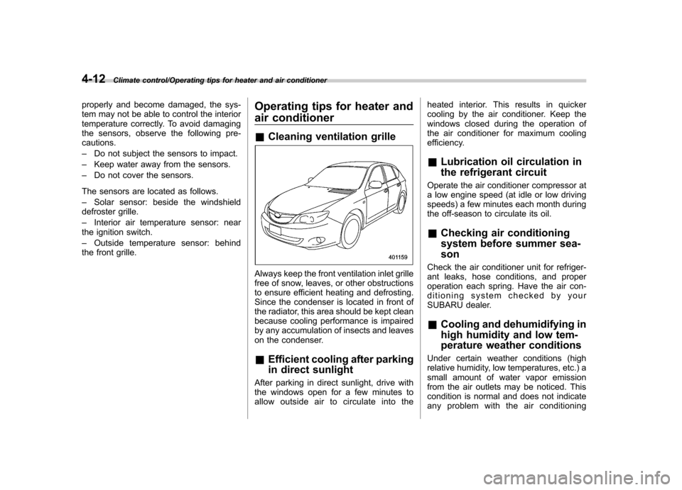
Always keep the front ventilation inlet grille
free of snow, leaves, or other obstructions
to ensure efficient heating and defrosting.
Since the condenser is located in front of
the radiator, this area should be kept clean
because cooling performance is impaired
by any accumulation of insects and leaves
on the condenser. &Efficient cooling after parking
in direct sunlight
After parking in direct sunlight, drive with
the windows open for a few minutes to
allow outside air to circulate into the heated interior. This results in quicker
cooling by the air conditioner. Keep the
windows closed during the operation of
the air conditioner for maximum cooling
efficiency. &
Lubrication oil circulation in
the refrigerant circuit
Operate the air conditioner compressor at
a low engine speed (at idle or low driving
speeds) a few minutes each month during
the off-season to circulate its oil. & Checking air conditioning
system before summer sea-son
Check the air conditioner unit for refriger-
ant leaks, hose conditions, and proper
operation each spring. Have the air con-
ditioning system checked by your
SUBARU dealer. & Cooling and dehumidifying in
high humidity and low tem-
perature weather conditions
Under certain weather conditions (high
relative humidity, low temperatures, etc.) a
small amount of water vapor emission
from the air outlets may be noticed. This
condition is normal and does not indicate
any problem with the air conditioning
Page 178 of 414
system. &Air conditioner compressor
shut-off when engine is
heavily loaded
To improve acceleration and gas mileage,
the air conditioner compressor is designed
to temporarily shut off during air condi-
tioner operation whenever the accelerator
is fully depressed such as during rapid
acceleration or when driving on a steepupgrade. & Refrigerant for your climate
control system
Your air conditioner uses ozone friendly
refrigerant HFC134a. Therefore, the meth-
od of adding, changing or checking the
refrigerant is different from the method for
CFC12 (freon). Consult your SUBARU
dealer for service. Repairs needed as a
result of using the wrong refrigerant are
not covered under warranty. Air filtration system
Replace the filter element according to the
replacement schedule as follows. This
schedule should be followed to maintain
the filter
’s dust collection ability. Under
extremely dusty conditions, the filter
should be replaced more frequently. It is
recommended that you have your filter
checked or replaced by your SUBARU
dealer. For replacement, use only a
genuine SUBARU air filter kit.
Replacement schedule: Every 12 months or 7,500 miles (12,000
km) whichever comes first
CAUTION
Contact your SUBARU dealer if the
following occurs, even if it is not yet
time to change the filter: . Reduction of the airflow through
the vents.
. Windshield gets easily fogged or
misted. NOTE
The filter can influence the air condi-
tioning, heating and defroster perfor-
mance if not properly maintained. &
Replacing an air filter
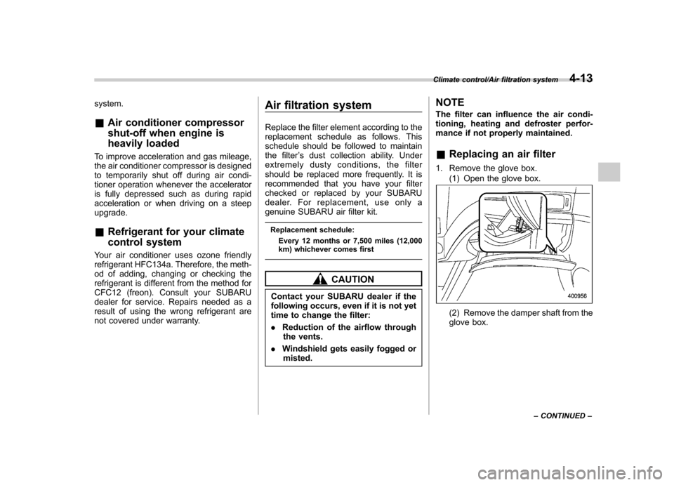
1. Remove the glove box. (1) Open the glove box.
(2) Remove the damper shaft from the
glove box.
Climate control/Air filtration system4-13
– CONTINUED –
Page 244 of 414
Fuel...................................................................... 7-3
Fuel requirements ............................................... 7-3
Fuel filler lid and cap ........................................... 7-4
State emission testing (U.S. only) ...................... 7-7
Preparing to drive ............................................... 7-8
Starting the engine .............................................. 7-9
Stopping the engine ........................................... 7-10
Remote engine start system (dealer option) .............................................................. 7-10
Starting your vehicle .......................................... 7-10
Remote start safety features ............................... 7-11
Entering the vehicle while it is running via remote start ................................................................. 7-11
Entering the vehicle following remote engine start shutdown ......................................................... 7-11
Pre-heating or pre-cooling the interior of the vehicle ............................................................. 7-11
Service mode ..................................................... 7-11
Remote engine start transmitter programming and programmable feature option ..................... 7-12
System maintenance .......................................... 7-12
Manual transmission –6 speeds (STI) ............. 7-14
Selecting reverse gear ........................................ 7-15
Shifting speeds .................................................. 7-15
Driving tips ........................................................ 7-16
Manual transmission –5 speeds (except
STI) ................................................................... 7-16
Shifting speeds .................................................. 7-17
Driving tips ........................................................ 7-17 Driver
’s Control Center Differential (DCCD)
(STI) ................................................................. 7-18
To change mode of driver ’s control center
differential ....................................................... 7-18
Auto mode ........................................................ 7-19
Manual mode ..................................................... 7-20
Temporary release ............................................. 7-21
SI-DRIVE (STI) .................................................... 7-22
Intelligent (I) mode ............................................. 7-22
Sport (S) mode .................................................. 7-22
Sport Sharp (S#) mode. ...................................... 7-23
SI-DRIVE selector .............................................. 7-23
Limited slip differential (LSD) (STI) .................. 7-24
Power steering ................................................... 7-24
Braking ............................................................... 7-24
Braking tips ....................................................... 7-24
Brake system .................................................... 7-25
Disc brake pad wear warning indicators ............. 7-25
ABS (Anti-lock Brake System) .......................... 7-26
ABS system self-check ...................................... 7-26
ABS warning light .............................................. 7-26
Electronic Brake Force Distribution (EBD) system ............................................................. 7-27
Steps to take if EBD system malfunctions ..... ..... 7-27
Vehicle Dynamics Control system .................... 7-28
Vehicle Dynamics Control system monitor..... ..... 7-29
Vehicle Dynamics Control OFF switch (STI) ... ..... 7-30
Vehicle Dynamics Control OFF switch (except STI) ................................................................. 7-31 Starting and operating
7