Page 270 of 488
270
3-5. Other interior features
Floor mat∗
∗
: If equipped
Make sure to only use floor mats
that are specifically designed for
use with the same model and model year as your vehicle. Fix them
securely in place on top of the carpet.
Insert the retaining hooks
(clips) into the floor mat eye-
lets.
Turn the upper knob of each
retaining hook (clip) to secure
the floor mats in place. *: Always align the ∆ marks.
The shape of the retaining hooks (clips) may differ from that shown in the
illustration. For details on the fixing procedure, refer to the instructions
supplied with the floor mat.
STEP 1
STEP 2
*
Page 271 of 488

271
3-5. Other interior features
3
Interior features
WARNING
Observe the following precautions.
Failure to do so may cause the driver's floor mat to slip, possibly interfering
with the pedals while driving. An unexpectedly high speed may result or it may
become difficult to stop the vehicle, leading to a serious accident.
■When installing the driver's floor mat
●Do not use floor mats designed for ot her models or different model year
vehicles, even if they are SUBARU Genuine floor mats.
●Only use floor mats designed for the driver's seat.
●Always install the floor mat securely using the retaining hooks (clips) pro-
vided.
●Do not use two or more floor mats on top of each other.
●Do not place the floor mat bottom-side up or upside-down.
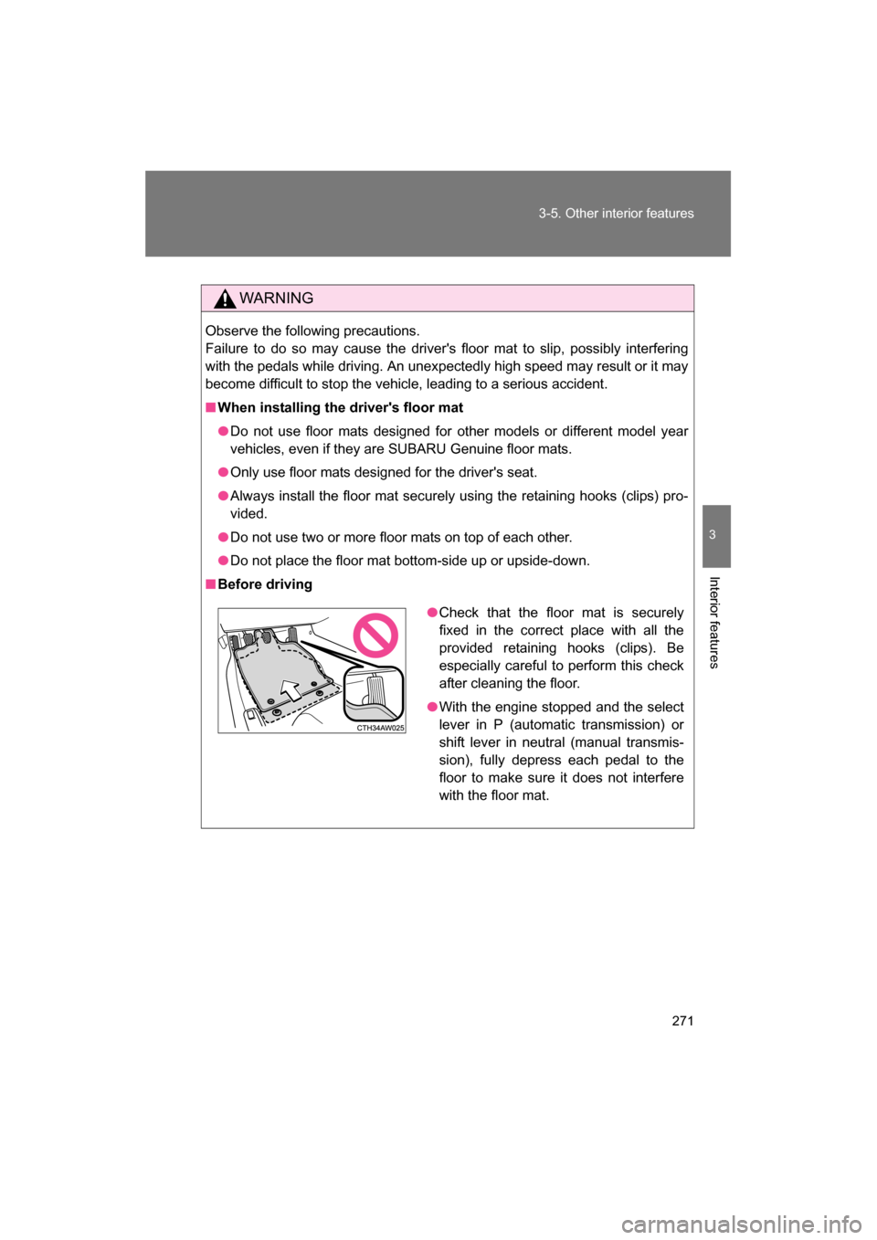
■Before driving
●Check that the floor mat is securely
fixed in the correct place with all the
provided retaining hooks (clips). Be
especially careful to perform this check
after cleaning the floor.
●With the engine stopped and the select
lever in P (automatic transmission) or
shift lever in neutral (manual transmis-
sion), fully depress each pedal to the
floor to make sure it does not interfere
with the floor mat.
Page 305 of 488
305
4-3. Do-it-yourself maintenance
4
Maintenance and care
■Adding distilled waterRemove the vent plug.
Add distilled water.
If the “UPPER LEVEL” line cannot be seen, check the fluid level by
looking directly at the cell.
Put the vent plug back on and close securely.
Low O.K.
STEP 1
STEP 2
STEP 3
Page 336 of 488

336
4-3. Do-it-yourself maintenance
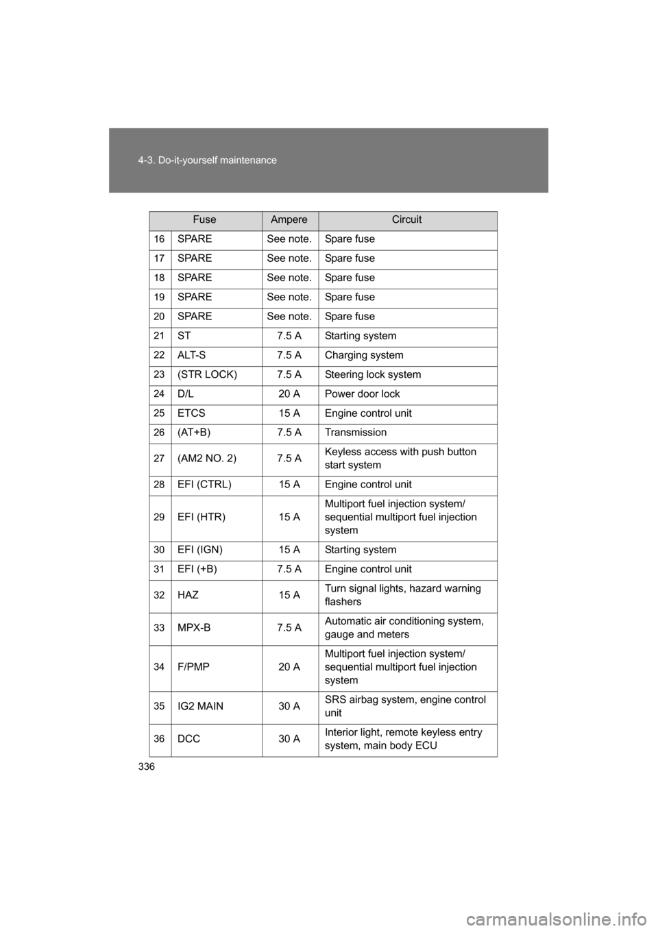
16SPARE See note. Spare fuse
17 SPARE See note. Spare fuse
18 SPARE See note. Spare fuse
19 SPARE See note. Spare fuse
20 SPARE See note. Spare fuse
21 ST 7.5 A Starting system
22 ALT-S 7.5 A Charging system
23 (STR LOCK) 7.5 A Steering lock system
24 D/L 20 A Power door lock
25 ETCS 15 A Engine control unit
26 (AT+B) 7.5 A Transmission
27 (AM2 NO. 2) 7.5 A Keyless access with push button
start system
28 EFI (CTRL) 15 A Engine control unit
29 EFI (HTR) 15 A Multiport fuel injection system/
sequential multiport fuel injection
system
30 EFI (IGN) 15 A Starting system
31 EFI (+B) 7.5 A Engine control unit
32 HAZ 15 A Turn signal lights, hazard warning
flashers
33 MPX-B 7.5 A Automatic air conditioning system, gauge and meters
34 F/PMP 20 A Multiport fuel injection system/
sequential multiport fuel injection
system
35 IG2 MAIN 30 A SRS airbag system, engine control
unit
36 DCC 30 A Interior light, remote keyless entry
system, main body ECU
FuseAmpereCircuit
Page 337 of 488
337
4-3. Do-it-yourself maintenance
4
Maintenance and care
Note
One of each of the following spare fuses are provided: 7.5 A, 10 A, 15
A, 20 A, 25 A, 30 A.37
HORN NO. 2 7.5 A Horn
38 HORN NO. 1 7.5 A Horn
39 H-LP LH LO 15 A Left-hand headlight (low beam)
40 H-LP RH LO 15 A Right-hand headlight (low beam)
41 H-LP LH HI 10 A Left-hand headlight (high beam)
42 H-LP RH HI 10 A Right-hand headlight (high beam)
43 INJ 30 A Multiport fuel injection system/
sequential multiport fuel injection
system
44 H-LP WASHER 30 A
45 AM2 NO. 1 40 A Starting system, engine control unit
46 EPS 80 A Electric power steering
47 A/B MAIN 15 A SRS airbag system
48 ECU-B 7.5 A Remote keyless entry system,
main body ECU
49 DOME 20 A Interior light
50 IG2 7.5 A Engine control unit
FuseAmpereCircuit
Page 338 of 488
338
4-3. Do-it-yourself maintenance
■Instrument panel
FuseAmpereCircuit
1 ECU ACC 10 A Main body ECU, outside rear view
mirrors
2 P/POINT No.2 15 A Power outlet
3 PANEL 10 A Illumination
4 TAIL 10 A Tail lights
5 DRL 10 A Daytime running light system
6 STOP 7.5 A Stop lights
7 OBD 7.5 A On-board diagnosis system
8 HEATER-S 7.5 A Air conditioning system
9 HEATER 10 A Air conditioning system
10 FR FOG LH 10 A Left-hand front fog light
11 FR FOG RH 10 A Right-hand front fog light
12 BK/UP LP 7.5 A Back-up lights
13 ECU IG1 10 A ABS, electric power steering
14 AM1 7.5 A Starting system
15 AMP 15 A
16 AT UNIT 15 A Transmission
17 GAUGE 7.5 A Gauge and meters, keyless access
with push button start system
18 ECU IG2 10 A Engine control unit
19 SEAT HTR LH 10 A Left-hand seat heater
20 SEAT HTR RH 10 A Right-hand seat heater
21 RADIO 7.5 A
22 P/POINT No.1 15 A Power outlet
Page 353 of 488

353
4-3. Do-it-yourself maintenance
4
Maintenance and care
■When replacing light bulbs
SUBARU recommends that you use genuine SUBARU products designed
for this vehicle.
Because certain bulbs are connected to circuits designed to prevent over-
load, non-genuine parts or parts not designed for this vehicle may be unus-able.
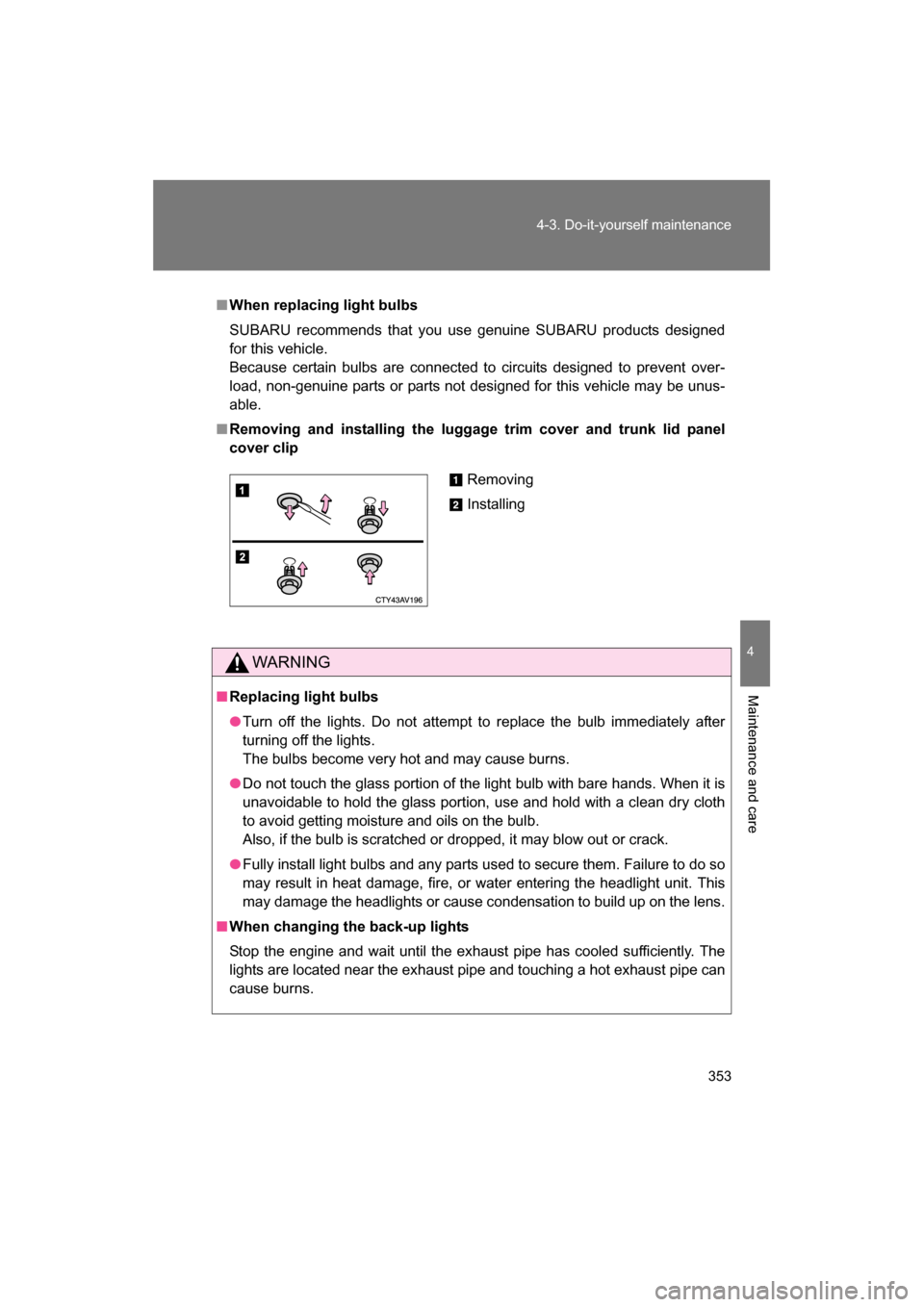
■Removing and installing the luggage trim cover and trunk lid panel
cover clip
WARNING
■Replacing light bulbs
●Turn off the lights. Do not attempt to replace the bulb immediately after
turning off the lights.
The bulbs become very hot and may cause burns.
●Do not touch the glass portion of the light bulb with bare hands. When it is
unavoidable to hold the glass portion, use and hold with a clean dry cloth
to avoid getting moisture and oils on the bulb.
Also, if the bulb is scratched or dropped, it may blow out or crack.
●Fully install light bulbs and any parts used to secure them. Failure to do so
may result in heat damage, fire, or water entering the headlight unit. This
may damage the headlights or cause condensation to build up on the lens.
■When changing the back-up lights
Stop the engine and wait until the exhaust pipe has cooled sufficiently. The
lights are located near the exhaust pipe and touching a hot exhaust pipe can
cause burns.
Removing
Installing
Page 357 of 488

5
When trouble arises
357
5-1. Essential information
If your vehicle needs to be towed
Emergency towingIf a tow truck is not available in an emergency, your vehicle may be
temporarily towed using a cable or chain secured to the emergency
towing eyelet to move the vehicle to a safe location or to free a stuck
vehicle from sand or snow. This should only be attempted on hard
surfaced roads for short distances at low speeds.
A driver must be in the vehicle to steer and operate the brakes. The
vehicle's wheels, drive train, axles, steering and brakes must be in
good condition.
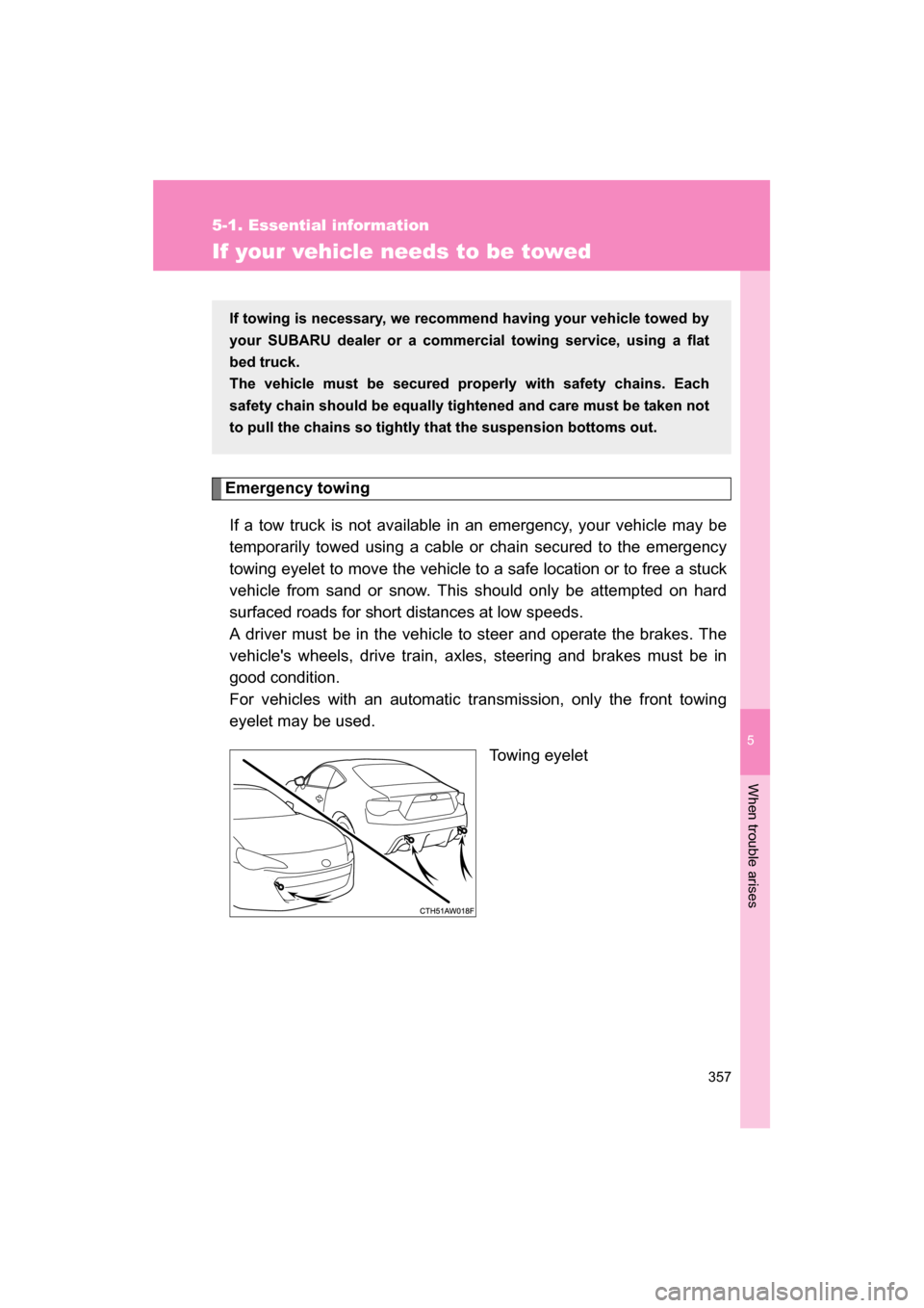
For vehicles with an automatic transmission, only the front towing
eyelet may be used. Towing eyelet
If towing is necessary, we recommend having your vehicle towed by
your SUBARU dealer or a commercial towing service, using a flat
bed truck.
The vehicle must be secured properly with safety chains. Each
safety chain should be equally tightened and care must be taken not
to pull the chains so tightly that the suspension bottoms out.