Page 209 of 280

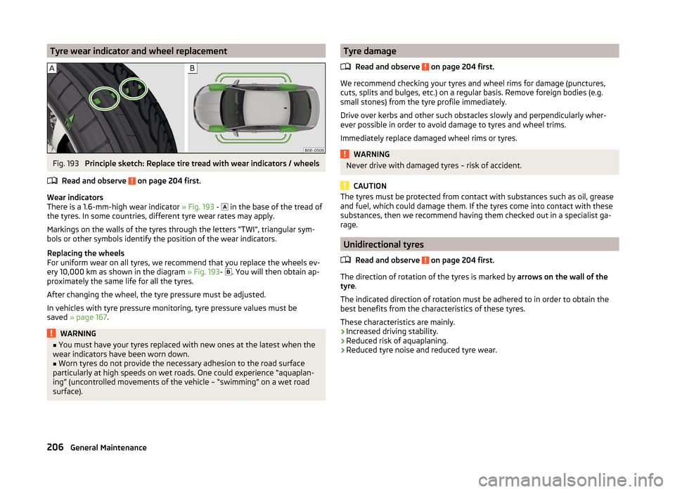
Tyre wear indicator and wheel replacementFig. 193
Principle sketch: Replace tire tread with wear indicators / wheels
Read and observe
on page 204 first.
Wear indicators
There is a 1.6-mm-high wear indicator » Fig. 193 -
in the base of the tread of
the tyres. In some countries, different tyre wear rates may apply.
Markings on the walls of the tyres through the letters “TWI”, triangular sym- bols or other symbols identify the position of the wear indicators.
Replacing the wheels
For uniform wear on all tyres, we recommend that you replace the wheels ev-
ery 10,000 km as shown in the diagram » Fig. 193-
. You will then obtain ap-
proximately the same life for all the tyres.
After changing the wheel, the tyre pressure must be adjusted.
In vehicles with tyre pressure monitoring, tyre pressure values must be
saved » page 167 .
WARNING■
You must have your tyres replaced with new ones at the latest when the
wear indicators have been worn down.■
Worn tyres do not provide the necessary adhesion to the road surface
particularly at high speeds on wet roads. One could experience “aquaplan-
ing” (uncontrolled movements of the vehicle – “swimming” on a wet road
surface).
Tyre damage
Read and observe
on page 204 first.
We recommend checking your tyres and wheel rims for damage (punctures,
cuts, splits and bulges, etc.) on a regular basis. Remove foreign bodies (e.g.
small stones) from the tyre profile immediately.
Drive over kerbs and other such obstacles slowly and perpendicularly wher-
ever possible in order to avoid damage to tyres and wheel trims.
Immediately replace damaged wheel rims or tyres.
WARNINGNever drive with damaged tyres – risk of accident.
CAUTION
The tyres must be protected from contact with substances such as oil, grease
and fuel, which could damage them. If the tyres come into contact with these
substances, then we recommend having them checked out in a specialist ga-
rage.
Unidirectional tyres
Read and observe
on page 204 first.
The direction of rotation of the tyres is marked by arrows on the wall of the
tyre .
The indicated direction of rotation must be adhered to in order to obtain the
best benefits from the characteristics of these tyres.
These characteristics are mainly.
› Increased driving stability.
› Reduced risk of aquaplaning.
› Reduced tyre noise and reduced tyre wear.
206General Maintenance
Page 219 of 280

WARNING (Continued)■In case of incorrect treatment of the wheel bolts, the wheel can loosen
when the car is moving.■
Drive cautiously and only at a moderate speed until the tightening torque
has been checked.
Loosening/tightening wheel bolts
Fig. 200
Changing a wheel: Loosening the
wheel bolts
Before removing the wheel bolts, remove the wheel bolt caps.
Release
›
Push the wheel wrench onto the wheel bolt to the stop 1)
.
›
Grasp the end of the wrench and turn the bolt about one turn in the direction
of the arrow » Fig. 200.
Tightening
›
Push the wheel wrench onto the wheel bolt to the stop 1)
.
›
Grasp the end of the wrench and turn the bolt against the direction of the
arrow » Fig. 200 , until it is tight.
After tightening the wheel bolts, replace the caps.
WARNINGIf it proves difficult to undo the bolts, carefully apply pressure to the end of
the wrench with your foot. Keep hold of the vehicle when doing so, and
make sure you keep your footing.Raising the vehicleFig. 201
Jacking points for the jack Version 1/version 2
Fig. 202
Schematic diagram: Positioning the jack
The jack from the vehicle tool kit must be used in order to raise the vehicle.
Position the car jack at the jacking point closest to the flat tyre .
Jacking points – version 1
The jacking points are located on the metal bar of the lower beam.
Their positions are indicated by embossed markings
A
» Fig. 201 in the side of
the lower beam.
Jacking points – version 2
The mounting points are located on the metal bar of the lower beam in the re-
cess at the bottom of the plastic lower-beam casing
B
» Fig. 201 .
1)
Use the appropriate adapter for undoing and tightening the anti-theft wheel bolts
» page 217.
216Do-it-yourself
Page 245 of 280
Dimensions - Octavia CombiFig. 237
Schematic diagram: Vehicle dimensions
Vehicle dimensions for operating weight without driver (in mm)
» Fig. 237SpecificationOctavia EstateOCTAVIA Estate 4x4OCTAVIA Estate RSOCTAVIA EstateSCOUTA
Height
Basic dimension1465 a)
/1463 b)1465a)
/1463 b)14521531Vehicles with off-road package.1480a)
/1478 b)1480a)
/1478 b)--Vehicles with SPORT package1450a)
/1448 b)---G-TEC vehicles1465---BFront track
» table on page 243CWidth1814181418141814DRear track » table on page 243EWidth including exterior mirror2017201720172017F
Clearance
Basic dimension140139127171Vehicles with off-road package.155154- Vehicles with SPORT package125---G-TEC vehicles140--- 242Technical data
Page 248 of 280
Departure angle - Octavia CombiFig. 239
Schematic diagram: Departure
angle
Angle » Fig. 239
Departure angle, front
Departure angle, rear
Departure angle
The values shown indicate the maximum incline of an embankment on which the vehicle can drive at a slow speed without collision of the bumper or under-
body.
The values listed correspond to the maximum front or rear axle loadABDeparture angle (°)» Fig. 239Octavia EstateOCTAVIA Estate 4x4OCTAVIA Estate RSOCTAVIA Estate SCOUTABABABABBasic dimension13.912.214.212.5----Vehicles with off-road package.14.913.215.312.4--16.713.8Vehicles with SPORT package12.812.4--12.812.3--245Technical data