2014 Seat Ibiza 5D ECU
[x] Cancel search: ECUPage 86 of 240

Operation
●
If the vehicle cannot be unlocked or locked
by using the radio frequency remote control,
the remote control key will have to be re-
synchronised. For this, go to your technical
services. Changing the battery
If the battery indicator does not flash when
the buttons are pushed, the battery must be
replaced.
CAUTION
The use of inappropriate batteries may dam-
age the radio frequency remote control. For
this reason, always replace the dead battery
with another of the same size and power. For the sake of the environment
Used batteries must be disposed of at an ap-
propriate waste facility or through an author-
ised service, given that their components can
affect the environment. Synchronising the remote control key
If it is not possible to unlock or lock the door
with the remote control, it should be re-
synchronised. While the vehicle is open:
– Press the button
2
››› Fig. 84 on the re-
mot e c
ontrol.
– Then close the vehicle using the key shaft
within one minute.
Whil
e the vehicle is closed:
– Press the button
1
››› Fig. 84 on the re-
mot e c
ontrol.
– Then close the vehicle using the key shaft
within one minute.
It i
s possible that the vehicle could no longer
be opened and closed with the remote con-
trol if the button is repeatedly pressed
outside of the effective range of the radio fre-
quency remote control. The remote control
key will have to be resynchronised.
Spare remote control keys are available at
your Technical Service, where they must be
matched to the locking system.
Up to five remote control keys can be used.
Anti-theft alarm system* Description of anti-theft alarm
system* The anti-theft alarm makes it more difficult to
break into the vehicle or steal it. The systemwill initiate acoustic and optical warning sig-
nals when your vehicle is tried to be forced.
The anti-theft alarm system is automatically
switched on when locking the vehicle. The
system is immediately activated and the turn
signal light located on the driver door will
flash along with the turn signals, indicating
that the alarm and the locking security sys-
tem (double lock) have been turned on.
If any of the doors or the bonnet are open,
they will not be included in the protection
zones of the vehicle when the alarm is con-
nected. If the door or the bonnet are subse-
quently closed, they will be automatically in-
cluded in the protection areas of the vehicle
and the turn signals will flash accordingly
when the doors close.
● The turn signal light will flash twice on
opening and deactivating the alarm.
● The turn signal light will flash once on clos-
ing and activating the alarm.
When does the system trigger an alarm?
The system triggers an alarm, if the following
unauthorised actions are carried out when
the vehicle is locked:
● Mechanical opening of the vehicle with the
vehicle key without switching on the ignition
in the next 15 seconds (in certain markets,
such as the Netherlands, the alarm is activa-
ted immediately).
84
Page 102 of 240

Operation
– The mirrors demist for some minutes to
prevent draining the battery unnecessarily.
– If necessary, press the button again to re-
peat the function.
– The exterior mirror heating is not activated
in temperatures above approximately
+20 °C (+68 °F).
Folding in exterior mirrors* – Turn the control ››› Fig. 97 to position
t
o
f
old in the exterior mirrors. You should al-
ways fold in the exterior mirrors if you are
driving through an automatic car wash.
This will help prevent damage.
Folding exterior mirrors back out to the
extended position*
– Turn the knob to position L or R to return
the exterior mirrors to their original posi-
tion ››› .
WARNING
● Convex or aspheric mirrors increase the
field of vision however the objects appear
smaller and further away in the mirrors. If you
use these mirrors to estimate the distance to
vehicles behind you when changing lane, you
could make a mistake. Risk of accident.
● If possible, use the rear vision mirror to es-
timate distances to vehicles behind you.
● Make sure that you do not get your finger
trapped between the mirror and the mirror base when folding back the mirrors. Risk of
injury!
For the sake of the environment
The exterior mirror heating should be switch-
ed off when it is no longer needed. Other-
wise, it is an unnecessary fuel waste. Note
● If the electrical adjustment ever fails to op-
erate, the mirrors can be adjusted by hand by
lightly pressing the edge of the mirror glass.
● In vehicles with electric exterior mirrors,
the following points should be observed: if, due to an external force (e.g. being knocked
while manoeuvring), the adjustment of the
mirror housing is altered, the mirror will have
to be fully folded electrically. Do not readjust
the rear vision mirror housing by hand, as
this will interfere with the mirror adjuster
function.
● The rear vision mirrors can be adjusted sep-
arately or simultaneously, as described
above.
● The fold-in function on the exterior mirrors
will not activate at speeds over 40 km/h
(25 mph). Seats and head restraints
Adjusting the seat and head
restraints
Adjusting the front seats Read the additional information carefully
››› page 11 WARNING
● Never adjust the driver or front passenger
seat while the vehicle is in motion. While ad-
justing your seat, you will assume an incor-
rect sitting position. Risk of fatal accidents.
Adjust the driver or front passenger seat only
when the vehicle is stationary.
● To reduce the risk of injury to the driver and
front passenger in case of a sudden braking
or an accident, never drive with the backrest
tilted towards the rear. The maximum protec-
tion of the seat belt can be achieved only
when the backrests are in an upright position
and the driver and front passenger have prop-
erly adjusted their seat belts. The further the
backrests are tilted to the rear, the greater
the risk of injury due to improper positioning
of the belt web!
● Exercise caution when securing the seat
height into forwards/backwards position. In-
juries can be caused if the seat height is ad-
justed without due care and attention. 100
Page 103 of 240

Seats and head restraints
●
To move the seat lengthways, pull upwards
and not sideways on the lever, as the force
exerted on it in this position could damage it. Folding and opening the front seat
backrests
3 Applies to vehicles with 3 doors:
Fig. 98
Front seats: lever for folding down the
backrest. Vehicles without the Easy-Entry function
– To fold
the backrest, pull the lever 1 up-
wards and push the backrest forwards.
– To unfold
the backrest, push it back.
V
ehicles with the Easy-Entry function
– To fold the backrest, pull the lever 1 up-
wards and push the backrest forwards. You
can push the seat forwards at the same
time to make entry to the rear seats easier. –
To unfold the backrest, first move the seat
c
ompletely back.
The Ea
sy-Entry function facilitates the access
to the vehicle rear seats. Before lifting the
backrest, return the seat to the original posi-
tion. The seat inserts when the backrest is lif-
ted.
Removing or adjusting head restraints Fig. 99
Adjusting and removing the head re-
straints. Adjusting height (front seats)
– Press the button on the side and pull up-
wards to the desired position.
– To lower the head restraint, press the but-
ton and push head restraint downwards.
– Make sure that it engages securely into one
of its positions. Adjusting height (rear seats)
– Press the button on the side and pull up-
wards to the desired position.
– To lower the head restraint, press the but-
ton and push head restraint downwards.
– Make sure that the head restraint engages
securely in one of its positions ››› page 33.
Removing the head restraint – Push the head restraint up as far as it will
go.
– Press the button ››› Fig. 99 (arrow).
– Pull head restraint out of fitting without re-
leasing the button.
Fitting the head restraint
– Insert the head restraint into the guides on
the corresponding backrest.
– Push head restraint down.
– Adjust the head restraint to suit body size
››› page 32 . WARNING
The safe driving chapter contains important
information, tips, suggestions and warnings
that you should read and observe for your
own safety and the safety of your passengers
››› page 29.
» 101
Technical specifications
Advice
Operation
Safety
The essentials
Page 105 of 240

Seats and head restraints
Folding down rear seats Fig. 101
Folding up the rear seat cushion. Fig. 102
Button for unlocking the rear back-
rest. Folding seat down
– Remove the head restraint ››› page 101.
– Pull the front edge of the seat cushion
››› Fig. 101 1 upwards in the direction of
the arrow. –
Lift the cushion 2 forwards in the direc-
tion of the arrow.
– Pull the release button ››› Fig. 102 in the di-
rection of the arrow and fold the backrest forwards.
– Insert the head restraints in the spaces on
the rear of the seat cushion which are visi-
ble when the seat cushion is lowered.
Folding seat forward
– Remove the head restraints from the
spaces in the seat cushion.
– Lift the backrest, and before securing it, re-
place the head restraints in the seat cush-
ion, and then click the seat correctly onto
the locking rails.
– Once the backrest is locked, pull on the
central seat belt or directly on the backrest
to check that the backrest has properly en-
gaged in position.
– Check that the position lever is in neutral
position.
– Lower the cushion and push it backwards
below the seat belt buckles.
– Press the front part of the cushion down-
wards.
On split rear seats*, the backrest and cush-
ion can be lowered and raised respectively in
two sections. WARNING
● Please be careful when folding back the
backrest! Injuries can be caused if the seat
height is adjusted without due care and at-
tention.
● Do no trap or damage seat belts when rais-
ing the backrest.
● After raising the backrest, check it has en-
gaged properly in position. Do this by pulling
on the central seat belt or directly on the
backrest and check that the position lever is
in the neutral position.
● The three point automatic seat belt only
works correctly when the backrest of the cen-
tral seat is correctly engaged. 103Technical specifications
Advice
Operation
Safety
The essentials
Page 110 of 240

Operation
CAUTION
Always use the correct type of plugs to avoid
damaging the sockets. Note
● The power sockets will only work with the
ignition on.
● The use of electrical appliances with the
engine switched off will cause a battery dis-
charge. Auxiliary audio connection (AUX)*
Fig. 116
Centre console: AUX Connection. –
Insert the pin as far as possible ››› Fig. 116
( ››› Booklet Radio ). L
ug gage compartment
Loading the luggage compartment Fig. 117
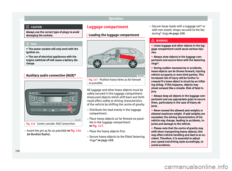
Position heavy items as far forward
as possible. All luggage and other loose objects must be
safely secured in the luggage compartment.
Unsecured objects which shift back and forth
could affect safety or driving characteristics
of the vehicle by shifting the centre of gravity.
– Distribute the load evenly in the luggage
compartment.
– Place heavy objects as far forward as possi-
ble in the luggage compartment
››› Fig. 117 .
– Plac
e the heavy objects first.
– Secure heavy objects to the fitted fastening
rings* ››› page 109. –
Secur
e loose loads with a luggage net* or
with non-elastic straps secured to the fas-
tening* rings ››› page 109. WARNING
● Loose luggage and other objects in the lug-
gage compartment could cause serious inju-
ries.
● Always stow objects in the luggage com-
partment and secure them with the fastening
rings*.
● During sudden manoeuvres or accidents,
loose objects can be thrown forward, injuring
vehicle occupants or even third parties. This
increased risk of injury will be further in-
creased if a loose object is struck by an inflat-
ing airbag. If this happens, objects may
shoot outward like a missile. Risk of fatal in-
jury.
● Always keep all objects in the luggage com-
partment and use appropriate grips to secure
them, particularly in the case of heavy ob-
jects.
● Never exceed the allowed axle weights or
allowed maximum weight. If said weights are
exceeded, the driving characteristics of the
vehicle may change, leading to accidents, in-
juries and damage to the vehicle.
● Please note that the centre of gravity may
shift when transporting heavy objects; this
may affect vehicle handling and lead to an ac-
cident. Therefore, it is essential to adjust
your speed and driving style accordingly, to
avoid accidents. 108
Page 111 of 240

Transport and practical equipment
●
Never leave your vehicle unattended, espe-
cially when the rear lid is open. Children
could climb into the luggage compartment,
closing the door behind them; they will be
trapped and run the risk of death.
● Never allow children to play in or around
the vehicle. Close and lock all the doors and
rear lid when you leave the vehicle. Before
you lock the vehicle, make sure that there are
no adults or children in the vehicle.
● Please observe the notes on the ››› page 29. CAUTION
Hard objects on the rear shelf could chafe
against the wires of the heating element in
the heated rear window and cause damage. Note
● The tyre pressure must be adjusted accord-
ing to the load. When necessary check the
tyre pressures on the label located on the in-
side fuel tank flap ››› page 177.
● Air c ir
culation in the vehicle helps reduce
fogging of the windows. Used air escapes
through ventilation slits in the side trim of
the luggage compartment. Ensure that the
ventilation slots are never covered.
● Straps for securing the load to the fasten-
ing rings* are commercially available from ac-
cessory shops. Fastening rings*
3 Applies to the model: IBIZA ST
Fig. 118
Location of fastening rings in lug-
gage compartment. There may be four fastening rings included in
the luggage compartment for fastening lug-
gage and other objects
››› Fig. 118 (arrows).
– Alw
ays use suitable and undamaged straps
to secure luggage and other objects to the
fastening rings ››› in Loading the lug-
gage compartment on page 108.
– Pull up the fastening rings to attach the
straps.
Example: An object weighing 4.5 kg is lying
unsecured in the vehicle. During a frontal col-
lision at a speed of 50 km/h (31 mph), this
object generates a force corresponding to 20
times its weight. That means that the effec-
tive weight of the object increases to approxi-
mately 90 kg. You can imagine the severity of the injuries which might be sustained if this
“object” strikes an occupant as it flies
through the interior of the vehicle. This in-
creased risk of injury will be further increased
if a loose object is struck by an inflating air-
bag.
WARNING
● If pieces of baggage or other objects are se-
cured to the fastening rings with inappropri-
ate or damaged retaining cords, injuries
could result in the event of braking manoeu-
vres or accidents.
● Never secure a child seat on the fastening
rings. Luggage net*
3 Applies to the model: IBIZA ST
Fig. 119
Stretched luggage net.
» 109
Technical specifications
Advice
Operation
Safety
The essentials
Page 112 of 240

Operation
The luggage net can be used to secure and
retain light items in the luggage compart-
ment.
Luggage net
– Secure the luggage net to the four fasten-
ing rings ››› Fig. 119 (arrows). WARNING
The luggage net should only be used to hold
objects weighing up to 5 kg. Heavier objects
cannot be safely secured (risk of injury). Rear shelf
Fig. 120
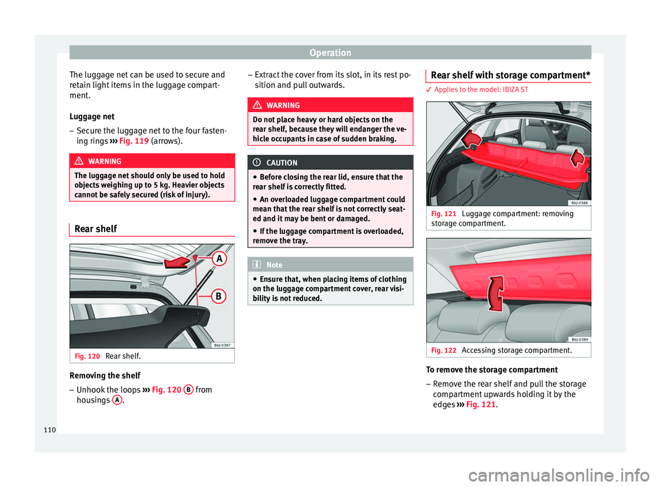
Rear shelf. Removing the shelf
–
Unhook the loops ››› Fig. 120 B from
housings A . –
Extract the cover from its slot, in its rest po-
sition and pull outwards. WARNING
Do not place heavy or hard objects on the
rear shelf, because they will endanger the ve-
hicle occupants in case of sudden braking. CAUTION
● Before closing the rear lid, ensure that the
rear shelf is correctly fitted.
● An overloaded luggage compartment could
mean that the rear shelf is not correctly seat-
ed and it may be bent or damaged.
● If the luggage compartment is overloaded,
remove the tray. Note
● Ensure that, when placing items of clothing
on the luggage compartment cover, rear visi-
bility is not reduced. Rear shelf with storage compartment*
3 Applies to the model: IBIZA ST
Fig. 121
Luggage compartment: removing
storage compartment. Fig. 122
Accessing storage compartment. To remove the storage compartment
– Remove the rear shelf and pull the storage
compartment upwards holding it by the
edges ››› Fig. 121 .
110
Page 114 of 240

Operation
Securing the crossbars and the roof
carrier system Fig. 123
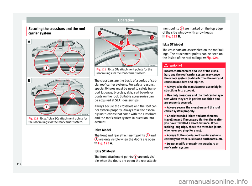
Ibiza/Ibiza SC: attachment points for
the roof railings for the roof carrier system. Fig. 124
Ibiza ST: attachment points for the
roof railings for the roof carrier system. The crossbars are the basis of a series of spe-
cial roof carrier systems. For safety reasons,
special fixtures must be used to safely trans-
port luggage, bicycles, skis, surf boards or
boats on the roof. Suitable accessories can
be acquired at SEAT dealerships.
Always secure the crossbars and the roof car-
rier system properly. Always take the assem-
bly instructions that come with the crossbars
and the roof carrier system in question into
account.
Ibiza Model
The front and rear attachment points
1 and
2 are only visible when the doors are open
››› Fig. 123
A.
Ibiza SC Model
The front attachment points 1 are only visi-
ble when the doors are open; the rear attach- ment points
3 are marked on the top edge
of the side window with arrow heads
››› Fig. 123
B
.
Ibiza ST Model
The crossbars are assembled on the roof rail-
ings. The attachment points can be seen on
the inside of the roof railings ››› Fig. 124
. WARNING
Incorrect attachment and use of the cross-
bars and the roof carrier system may cause
the whole system to detach from the roof and
cause an accident and injuries.
● Always take the manufacturer assembly in-
structions into account.
● Use only crossbars and the roof carrier sys-
tem when they are in perfect condition and
are properly secured.
● Always secure the crossbars and the roof
carrier system properly.
● Check threaded joints and attachments
travelling and if necessary tighten them after
you have travelled a short distance. When
making long trips, check the threaded joints
whenever you stop for a rest.
● Always fit the special roof carrier systems
correctly for wheels, skis and surfboards, etc.
● Do not modify or repair the crossbars or
roof carrier system. 112