Page 145 of 240

Driver assistance systems
Start-Stop function interruption
In the following situations, the Start-Stop
function will be interrupted and the engine
will automatically start:
● The vehicle starts moving.
● The brake pedal is pressed several times in
a row.
● The battery has been discharged excessive-
ly.
● The Start-Stop System is manually deacti-
vated.
● The windscreen de-mist function is turned
on.
● The temperature of the interior exceeds the
comfort limits ( A/C button).
● If the airflow is increased by more than 3
presses.
● Temperature setting HI or LO is selected.
● The engine coolant temperature is insuffi-
cient.
● The alternator is faulty, for example the V-
belt has ruptured.
● If any of the conditions described in the
previous section are not fulfilled. WARNING
Never allow the vehicle to move with the en-
gine off for any reason. You could lose control
of your vehicle. This could cause an accident
and serious injury. ●
The brake servo does not work with the en-
gine off. You need more force to stop the vehi-
cle.
● Power steering does not work when the en-
gine is not running. That is why it is much
more difficult to turn the steering wheel.
● Turn off the Start-Stop system when driving
through water (fording streams, etc.). Note
● For vehicles with the Start-Stop function
and a manual gearbox, when the engine is
started, the clutch must be pressed.
● When the conditions for the Start-Stop
function are not fulfilled, the instrument pan-
el displays the Start-Stop indicator dimmed.
● If the steering wheel is turned more than
270°, it will not be possible to start the vehi-
cle again. To start the vehicle, straighten the
steering wheel so that it is turned less than
270°. Activating and deactivating the Start-
Stop function
Fig. 141
The Start-Stop function button. Every time the ignition is switched on, the
Start-Stop function is automatically activa-
ted.
Manually deactivating the Start-Stop
function
– Press the
››› Fig. 141 button located on
the c entr
e console. When the Start-Stop
function is switched off, the warning lamp
comes on.
– If the Start-Stop function is operating then
the engine starts immediately.
»
143
Technical specifications
Advice
Operation
Safety
The essentials
Page 146 of 240

Operation
Switching the Start-Stop function on
manually – Press the
››› Fig. 141 button located on
the c entr
e console. The warning lamp will
switch off.
Driver messages Fig. 142
Display on the instrument panel dur-
ing Start-Stop function operation. When the engine is turned off by the Start-
Stop function, this is displayed on the instru-
ment panel.
If the Start-Stop system is not switched on,
the
warning lamp will appear on the instru-
ment
panel. Note
There are different versions of the dash pan-
el; the display of indications on the screen
may differ. Rear Assist
Operating and safety warnings WARNING
● The Rear Assist does not make it possible
to precisely calculate the distance from ob-
stacles (people, vehicles, etc.) and nor can it
overcome the system's own limits, hence us-
ing it may cause serious accidents and inju-
ries if used negligently or without due care.
The driver should be aware of his/her sur-
roundings at all times to ensure safe driving.
● The camera lens expands and distorts the
field of vision and displays the objects on the
screen in a different, vague manner. The per-
ception of distances is also distorted by this
effect. ●
Some objects may, due to the resolution of
the display screen - not be displayed in a sat-
isfactory manner or may not be displayed at
all. Take special care with thin posts, fences,
railings or trees that might not be displayed
on screen and could damage the vehicle.
● The rear assist has blind spots where it is
not possible to represent people or objects
(small children, animals and certain objects
cannot be detected in its field of vision). Mon-
itor the vehicle's surrounding area at all
times.
● Keep the camera lens clean, free of ice and
snow, and do not cover it.
● The system is not a replacement for driver
awareness. Supervise the parking operation
at all times, as well as the vehicle's surround-
ing area. Adapt your speed and driving style
at all times to suit visibility, weather, road
and traffic conditions.
● Do not be distracted from the traffic by
looking at the screen.
● The images on the rear assist screen are
only two-dimensional. Due to a lack of spatial
depth, protruding parts or holes in the road,
for example, are more difficult to detect or
may not be seen at all.
● Vehicle load modifies the representation of
the orientation lines displayed. The width
represented by the lines diminishes with ve-
hicle load. Pay special attention to the vehi-
cle's surroundings when the inside of the ve-
hicle of the luggage compartment is carrying
a heavy load. 144
Page 147 of 240

Driver assistance systems
●
In the following situations, the objects or
other vehicles shown in the navigation sys-
tem display appear to be further away or
closer than they really are: Pay special atten-
tion:
–On moving from a horizontal plane to a
slope.
– On moving from a slope to a horizontal
plane.
– If the vehicle is heavily loaded at the
rear.
– When the vehicle approaches objects
that are not on the ground surface or are
jutting out from it. These objects may al-
so be outside the camera's angle of vi-
sion when reversing. Note
It is important to take great care and pay spe-
cial attention if you are not yet familiar with
the system. Instructions for use
Fig. 143
On the rear bumper: location of the
rear assist camera A camera on the rear bumper aids the driver
during reverse parking or manoeuvring
››› Fig. 143 . The picture on the camera is dis-
p l
ayed together with orientation lines projec-
ted by the system on the display on the left of
the interior rear view mirror. The bottom of
the screen displays part of the bumper corre-
sponding to the registration plate area that
will be used as reference by the driver.
Necessary conditions for parking and
manoeuvring with the
The system should not be used in the follow-
ing cases:
● If the image displayed is not very reliable or
is distorted, for example low visibility or dirty
lens. ●
If the area behind the vehicle is not dis-
played very clearly or is incomplete.
● If the vehicle is heavily loaded at the rear.
● If the position and installation angle of the
camera have been changed, e.g. after a rear-
end collision. Have the system checked by a
specialised workshop.
Familiarising yourself with the system
To familiarise yourself with the system, the
orientation lines and their function, SEAT rec-
ommends practising parking and manoeu-
vring with the rear assist in a place without
too much traffic or in a car park when there
are good weather and visibility conditions.
Cleaning the camera lens
Keep the camera lens clean and clear of snow
and ice:
● Moisten the lens using a normal alcohol-
based glass cleaning product and clean the
lens with a dry cloth.
● Remove snow using a small brush.
● Use de-icing spray to remove any ice. CAUTION
● Never use abrasive cleaning products to
clean the camera lens.
● Do not use hot or warm water to remove ice
or snow from the camera lens. Doing so could
damage the camera. 145
Technical specifications
Advice
Operation
Safety
The essentials
Page 148 of 240

Operation
Parking and manoeuvring with the
rear assist Fig. 144
View of the left side of the interior
rear view mirror on the display: orientation
lines. Switching the system on and off
● The rear assist will switch on when the igni-
tion is on or the engine running, on engaging
reverse gear (manual gearbox) or on chang-
ing the selector lever to the R position (auto-
m atic
gearbox).
● The system switches off 8 seconds after
disengaging reverse gear (manual gearbox)
or removing the selector lever from the R po-
sition (automatic gearbox). The system will
also disconnect immediately after the igni-
tion is switched off.
Meaning of the orientation lines
››› Fig. 144 Side lines: extension of the vehicle (the
approximate width of the vehicle plus the
rear view mirrors) on the road surface.
End of the side lines:
the area marked in
green ends approximately 2 m behind
the vehicle on the road surface.
Intermediate line: indicates a distance of
approximately 1 m behind the vehicle on
the road surface.
Red horizontal line: indicates a safe dis-
tance of approximately 40 cm at the rear
of the vehicle on the road surface.
Parking manoeuvre
● Place the vehicle in front of the parking
space and engage reverse gear (manual
gearbox) or move the selector to the R posi-
tion (automatic gearbox).
● Reverse slowly, and turn the steering wheel
so that the side orientation lines lead to-
wards the parking space.
● Guide the vehicle into the parking space so
that the side orientation lines run parallel to
it. 1 2
3
4 Parking aid*
General information Various aid systems are in place to help in
parking and manoeuvring depending on the
vehicle’s equipment:
The rear parking aid
is an audible aid that
w
arns against obstacles behind the vehicle
››› page 147.
The front parking aid i
s an audible aid that
warns against obstacles both behind and in
front of the vehicle ›››
page 148.
Apart from the acoustic signals, when the ve-
hicle is equipped with a portable navigator
(PND), this visually displays information re-
garding front and/or rear areas. WARNING
● The sensors have blind spots in which ob-
stacles may not be detected.
● Always look out for small children and ani-
mals because the system will not always de-
tect them. Pay attention when reversing to
avoid accidents.
● The parking aid is not a replacement for
driver awareness. The driver must take full re-
sponsibility for parking and other manoeu-
vres. 146
Page 149 of 240

Driver assistance systems
Rear parking aid The parking aid system will use an audible
warning to indicate of the approach of any
object towards the rear of the vehicle.
Description
The acoustic parking aid system will measure
the distance between the rear of the vehicle
and any possible obstacle using four ultra-
sonic sensors located on the rear bumper.
The measuring range of the sensors starts
approximately and depending on the nature
of the obstacle
at a distance of:
● side of the rear bumper: 0.6 m
● middle of the rear bumper: 1.6 m
Activation
The system is activated by engagement of
the reverse gear. A brief audible warning con-
firms the activation and correct function of
the system.
Reverse gear
The distance warning will begin as soon as
an obstacle is detected by the system. The
frequency of the bleeps emitted by the sys-
tem will increase rapidly as the vehicle ap-
proaches the obstacle. After a distance lower
than approximately 30 cm, a continuous sig-
nal sounds (stop signal). The driver should
not reverse any further. Models with a factory-fitted towing bracket:
when the vehicle is less than 0.35 m away
the warning tone will sound continuously.
The driver should then not reverse any fur-
ther.
The warning tone volume decreases by 30%
3 seconds after it the system is triggered
if
the detected obstacle stays at a constant dis-
tance from the vehicle .
Provided that it is not in continuous mode,
the tone on the parking aid system stops
when it detects a wall parallel to the vehicle.
Trailer towing
For vehicles factory-fitted with a towing bar,
the parking aid system will not be activated
by the engagement of the reverse gear when
pulling a trailer, as the trailer's electric con-
nector will be plugged into the vehicle.
Possible faults
If a continuous beep sounds for some sec-
onds when the reverse gear is engaged, this
indicates that there is a fault in the parking
aid system. If the fault continues until the ig-
nition is turned off, the audible warning of
the fault will not be emitted every time the
system is reactivated (by engaging the re-
verse gear). Thus, the system ready indica-
tion will not sound either. Have the fault re-
paired by technical services as soon as possi-
ble. If there is no ready signal or no acoustic
warning signal, then the parking aid loud-
speaker is faulty and may not warn of obsta-
cles. To ensure that the system works proper-
ly, the sensors must be kept clean and free of
ice and snow.
CAUTION
● Please note that low obstacles detected by
the system may no longer be registered by
the sensors as the car moves closer, so the
system will not give any further warning. Cer-
tain kinds of obstacles, such as wire fences,
chains, thin posts or trailer draw bars, high
kerbs or painted railings, etc., may not al-
ways be detected by the system, so there is a
risk of damaging the vehicle in such cases.
● In some case, obstacles with edges and
bumps may not be detected immediately by
the system due to their geometry. Take spe-
cial care with this type of obstacle (corners,
rectangular objects, etc.), as they can cause
damage to the vehicle.
● Be especially careful when manoeuvring in-
to a corner between two perpendicular walls.
Pay special attention to the side distance
from the wall using the mirrors.
● The parking aid system does not replace
use of the mirrors for manoeuvres.
● External ultra-sonic sources (pneumatic
drills, construction machinery, other vehicles
with PDC) may interfere with the operation of
the system. » 147Technical specifications
Advice
Operation
Safety
The essentials
Page 150 of 240

Operation
●
Periodic cleaning of the sensors, take care
not to damage or scratch them. When clean-
ing with high pressure washers or steam
cleaners, the sensors should be sprayed for
only a very short period and from a distance
of more than 10 cm.
● If the licence plate (especially the front
one) is bent in such a way that it noticeably
juts out from the bumper, false alarms may
sound for the area in front of the vehicle. Rear parking aid with navigator view
Fig. 145
Parking aid view on the navigation
screen. When the parking aid system has been acti-
vated, the navigation view screen is also si-
multaneously activated (if one of the doors or
the rear lid is open, it must be closed before
the on-screen information can be viewed).
The distance of separation from the obstacle
can be estimated
››› Fig. 145 with the help of the segments around the vehicle. The white
segments represent obstacles located be-
tween 30 cm and 160 cm from the vehicle’s
rear. As the vehicle approaches an obstacle,
the segments are displayed closer to the ve-
hicle. The red segments represent obstacles
located at less than 30 cm from the front
bumper. At this point the driver should not
reverse any further.
Front parking aid Description
The acoustic parking aid system measures
the distance between the vehicle and any
possible obstacle using 8 ultrasonic sensors
(4 of which are located on the rear bumper
and 4 of which are located on the front
bumper).
The measuring range of the sensors starts
approximately and depending on the nature
of the obstacle
at a distance of:
● side of the front bumper: 0.6 m
● middle of the front bumper: 1.2 m
● side of the rear bumper: 0.6 m
● middle of the rear bumper: 1.6 m
Activation
The system may be activated in the following
ways: ●
Engage the reverse gear (a brief, sharp
acoustic signal confirms activation and the
correct operation of the system) or
● Push the central console button (a brief
confirmation signal will sound and the but-
ton’s LED will light up).
Disconnection
The system may be deactivated in the follow-
ing ways:
● Drive forwards at more than approx.
10 km/h (6 mph) or
● Press the button, or
● Switch the ignition off.
Manoeuvres
The distance warning will begin as soon as
an obstacle is detected in the system's field
of detection (front and rear). The frequency of
the bleeps emitted by the system will in-
crease rapidly as the vehicle approaches the
obstacle. Two speakers, one in the front and
one in the rear, indicate the location of the
obstacle ( front and rear, respectively).
After a distance lower than approximately 30
cm, a continuous signal sounds (stop signal).
At this point the driver should halt the vehi-
cle.
Models with a factory-fitted towing bracket:
when the vehicle is less than 0.35 m away
the warning tone will sound continuously.
148
Page 151 of 240

Driver assistance systems
The driver should then not reverse any fur-
ther.
The warning tone volume decreases by 30%
3 seconds after it is triggered if the detected
obstacle stays at a constant distance from
the vehicle.
Provided that it is not in continuous mode,
the tone on the parking aid system stops
when it detects a wall parallel to the vehicle.
Trailer towing
For vehicles factory-fitted with a towing bar,
the parking aid system will not be activated
by the engagement of the reverse gear when
pulling a trailer, as the trailer's electric con-
nector will be plugged into the vehicle.
Possible faults
If a continuous, sharp beep sounds for a few
seconds, there is a fault in the parking aid
system.
If the fault continues until the ignition is
turned off, the audible warning of the fault
will not be emitted every time the system is
reactivated (by engaging the reverse gear or
pressing the button). Thus, the system
ready indication will not sound either. Have
the fault repaired by technical services as
soon as possible.
If there is no ready signal or no acoustic
warning signal, then the parking aid loud- speaker is faulty and may not warn of obsta-
cles. To ensure that the system works proper-
ly, the sensors must be kept clean and free of
ice and snow.
CAUTION
● Please note that low obstacles detected by
the system may no longer be registered by
the sensors as the car moves closer, so the
system will not give any further warning. Cer-
tain kinds of obstacles, such as wire fences,
chains, thin posts or trailer draw bars, high
kerbs or painted railings, etc., may not al-
ways be detected by the system, so there is a
risk of damaging the vehicle in such cases.
● In some cases, obstacles with uniform
edges and bumps may not be detected imme-
diately by the system due to their geometry.
Take special care with this type of obstacle
(corners, rectangular objects, etc.), as they
can cause damage to the vehicle.
● Be especially careful when manoeuvring in-
to a corner between two perpendicular walls.
Pay special attention to the side distance
from the wall using the mirrors.
● The parking aid system does not replace
use of the mirrors for manoeuvres.
● External ultra-sonic sources (e.g. pneumat-
ic drills, construction machinery or other ve-
hicles equipped with PND) may interfere with
the operation of the system.
● Periodic cleaning of the sensors, take care
not to damage or scratch them. When clean-
ing with high pressure washers or steam cleaners, the sensors should be sprayed for
only a very short period and from a distance
of more than 10 cm.
●
If the licence plate (especially the front
one) is bent in such a way that it noticeably
juts out from the bumper, false alarms may
sound for the area in front of the vehicle. Front parking aid with navigator view
Fig. 146
Parking aid view on the navigation
screen. When the parking aid system has been acti-
vated, the navigation view screen is also si-
multaneously activated (if one of the doors or
the rear lid is open, it must be closed before
the on-screen information can be viewed).
The distance of separation from the obstacle
can be estimated
››› Fig. 146 with the help of
the segments around the vehicle. At the
front, the white segments indicate obstacles
located between 30 cm and 120 cm from the »
149Technical specifications
Advice
Operation
Safety
The essentials
Page 152 of 240

Operation
front of the vehicle. At the rear, these indi-
cate obstacles located between 30 cm and
160 cm from the vehicle’s rear. As the vehicle
approaches an obstacle, the segments are
displayed closer to the vehicle. The red seg-
ments represent obstacles located at less
than 30 cm from the bumper. At this point
the driver should not move forward/reverse
any further.
Cruise speed* (cruise control
system - CCS)
Description The CCS is able to maintain the set speed in
the range from approx. 30 km/h (19 mph) to
180 km/h (112 mph).
Once the speed setting has been saved, you
may take your foot off the accelerator.
WARNING
It could be dangerous to use the cruise con-
trol system if it is not possible to drive at con-
stant speed.
● Do not use the cruise control system when
driving in dense traffic, on roads with lots of
bends or on roads with poor conditions (with
ice, slippery surfaces, loose grit or gravel), as
this could cause an accident. ●
Always switch the cruise control system off
after using it in order to avoid involuntary
use.
● It is dangerous to use a set speed which is
too high for the current road, traffic or weath-
er conditions. Risk of accident. Note
The cruise control cannot maintain a constant
speed when descending downhill. It will in-
crease due to its own weight. Use the foot
brake to slow the vehicle. Switching the cruise control system
on and off
Fig. 147
Turn signal and main beam head-
light lever: switch and rocker switch for the
cruise control. Switching on the cruise control system
– Move the control ››› Fig. 147 A to the left
to ON.
Sw it
ching off the cruise control system
– Move the control A to the right to
OFF or
turn the ignition off when the vehicle is sta-
tionary.
When the cruise control is on and a speed is
programmed, the indicator
on the instru-
ment
panel* is lit.
If the cruise control system is switched off
,
the symbol is switched off. The system will
also be switched off fully when the 1st
gear
is engaged.*
Setting speed* Fig. 148
Turn signal and main beam head-
light lever: switch and rocker switch for the
cruise control. 150
 1
1 2
2 3
3 4
4 5
5 6
6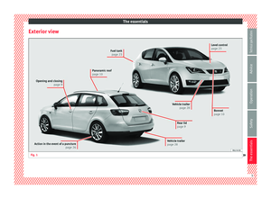 7
7 8
8 9
9 10
10 11
11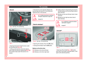 12
12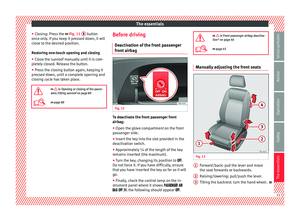 13
13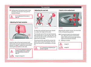 14
14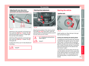 15
15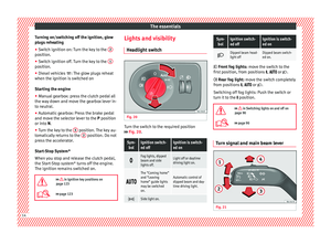 16
16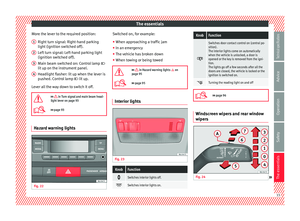 17
17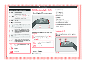 18
18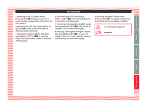 19
19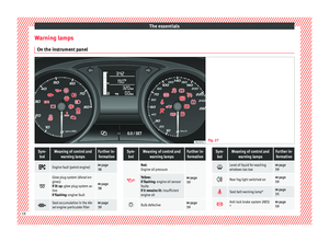 20
20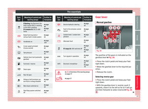 21
21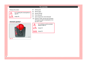 22
22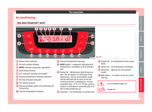 23
23 24
24 25
25 26
26 27
27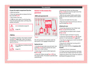 28
28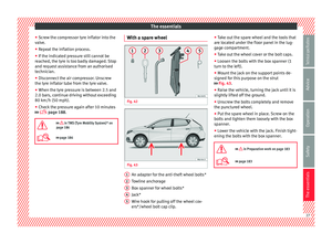 29
29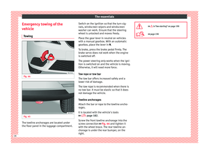 30
30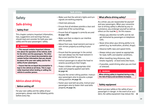 31
31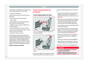 32
32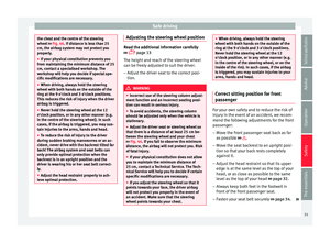 33
33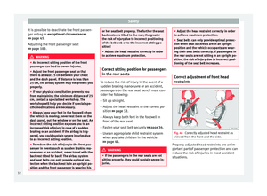 34
34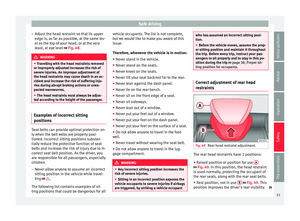 35
35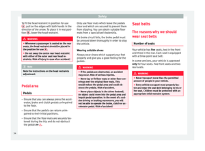 36
36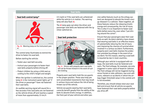 37
37 38
38 39
39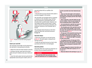 40
40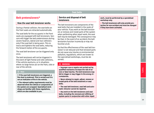 41
41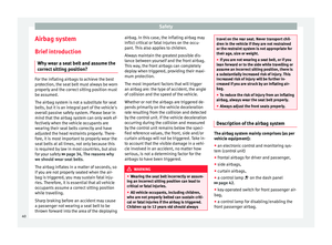 42
42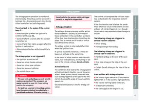 43
43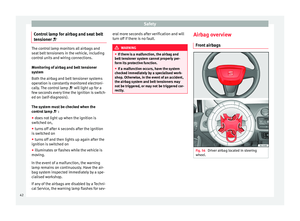 44
44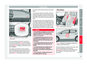 45
45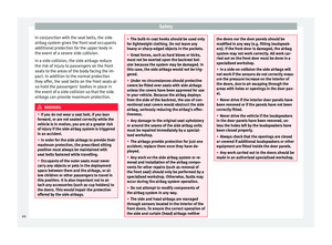 46
46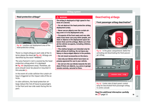 47
47 48
48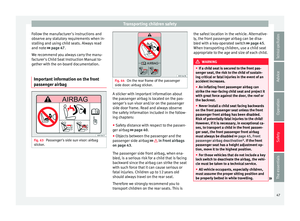 49
49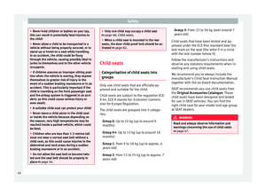 50
50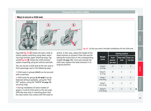 51
51 52
52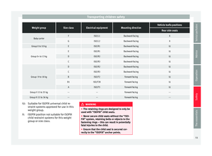 53
53 54
54 55
55 56
56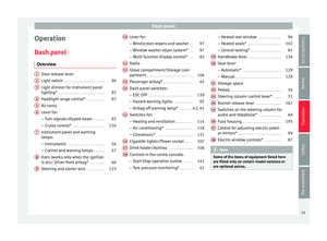 57
57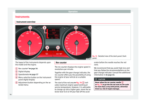 58
58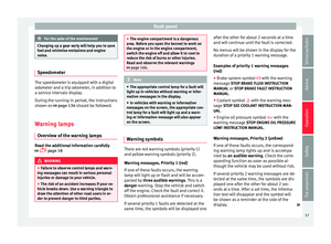 59
59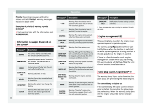 60
60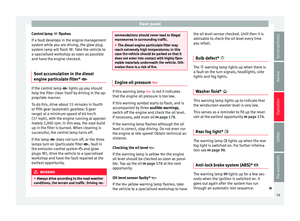 61
61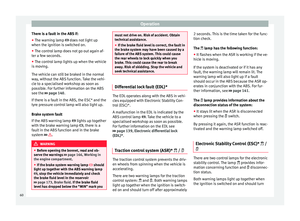 62
62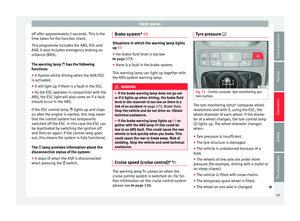 63
63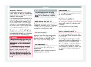 64
64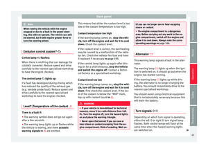 65
65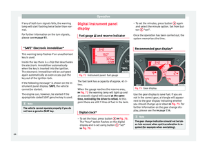 66
66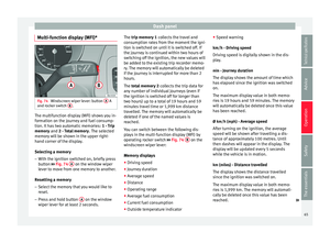 67
67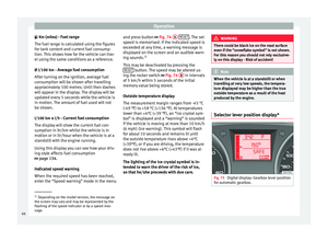 68
68 69
69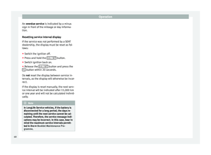 70
70 71
71 72
72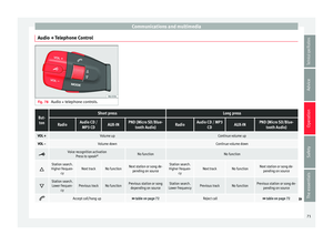 73
73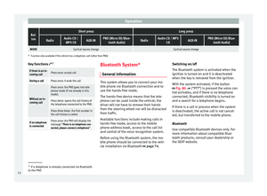 74
74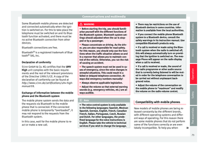 75
75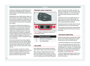 76
76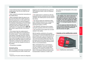 77
77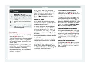 78
78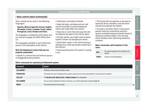 79
79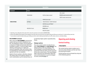 80
80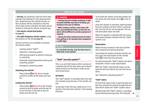 81
81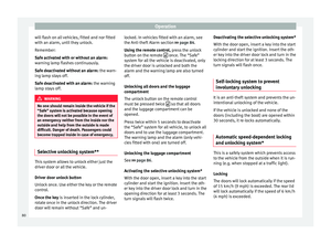 82
82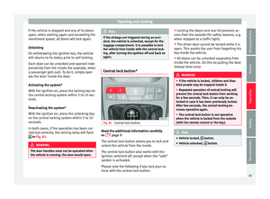 83
83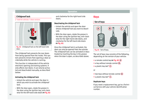 84
84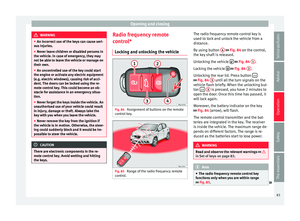 85
85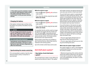 86
86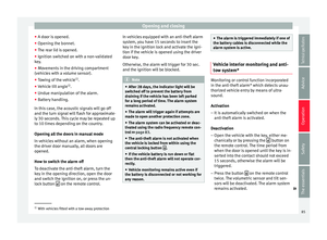 87
87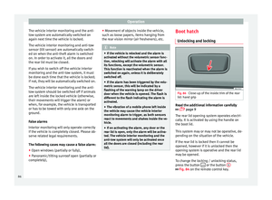 88
88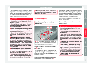 89
89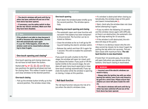 90
90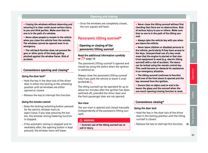 91
91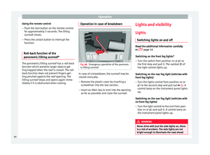 92
92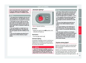 93
93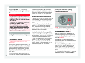 94
94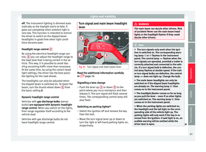 95
95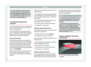 96
96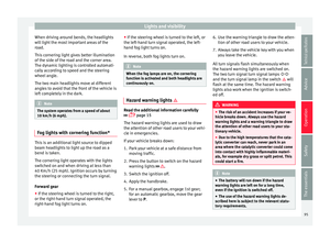 97
97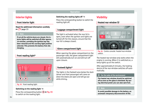 98
98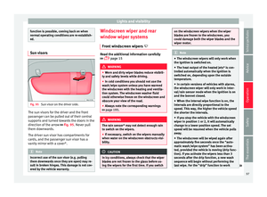 99
99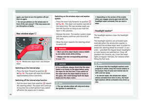 100
100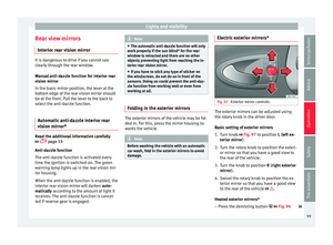 101
101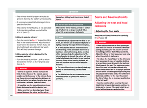 102
102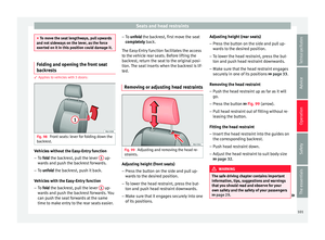 103
103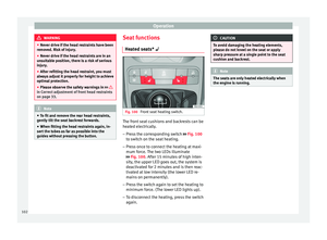 104
104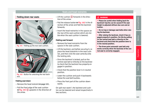 105
105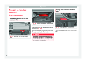 106
106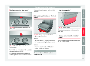 107
107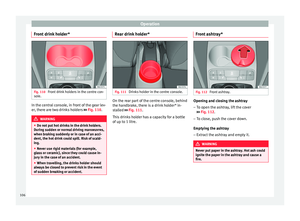 108
108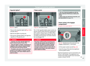 109
109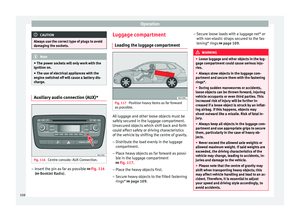 110
110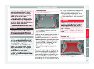 111
111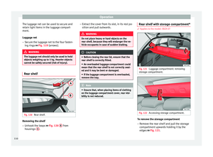 112
112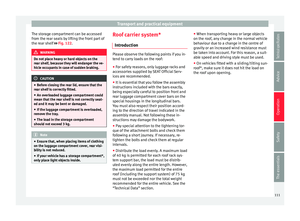 113
113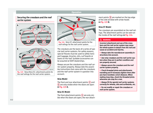 114
114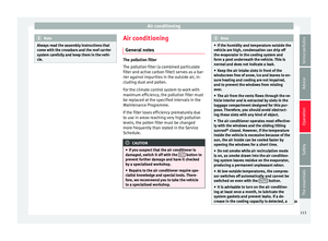 115
115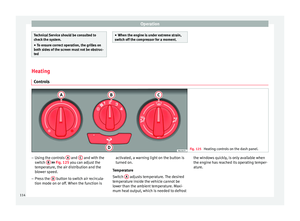 116
116 117
117 118
118 119
119 120
120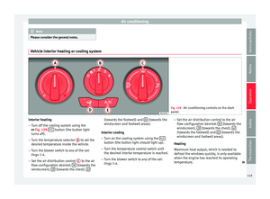 121
121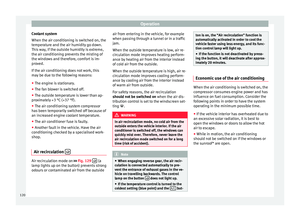 122
122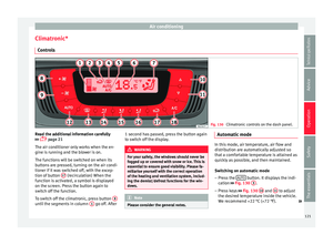 123
123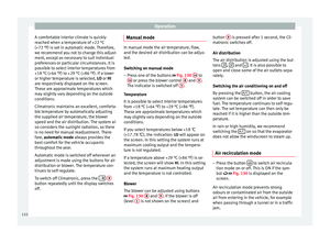 124
124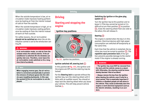 125
125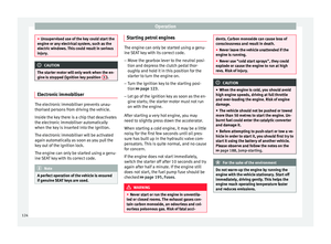 126
126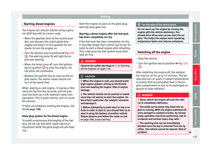 127
127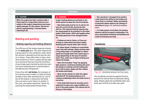 128
128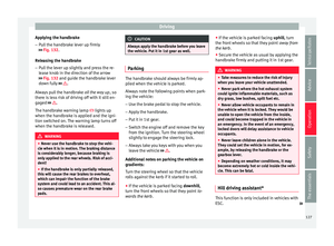 129
129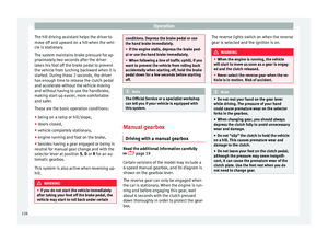 130
130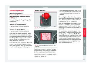 131
131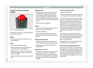 132
132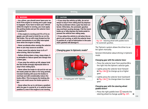 133
133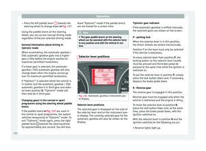 134
134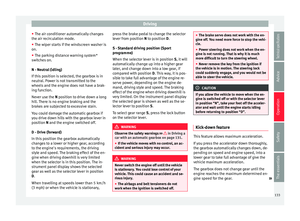 135
135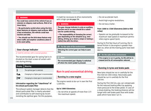 136
136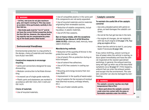 137
137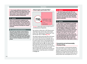 138
138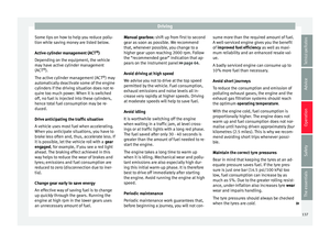 139
139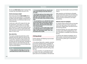 140
140 141
141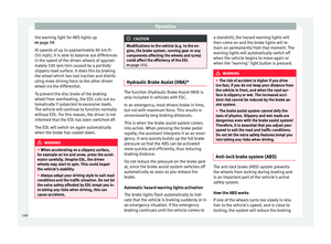 142
142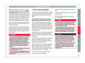 143
143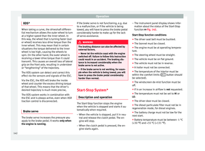 144
144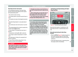 145
145 146
146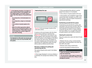 147
147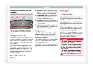 148
148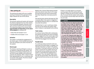 149
149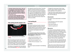 150
150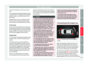 151
151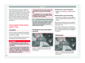 152
152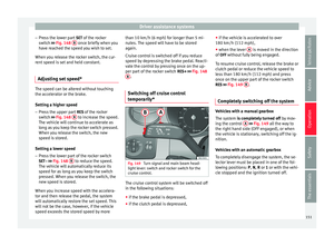 153
153 154
154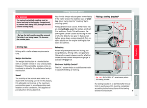 155
155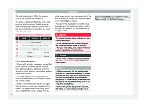 156
156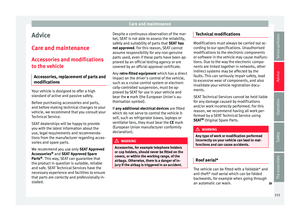 157
157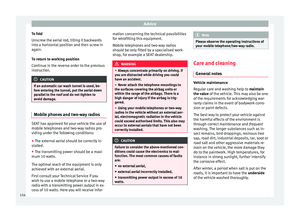 158
158 159
159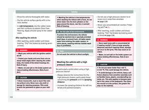 160
160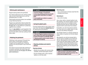 161
161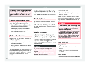 162
162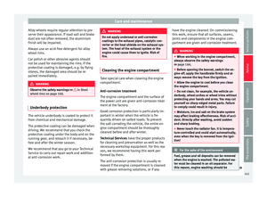 163
163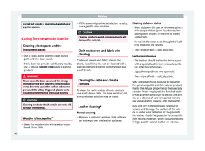 164
164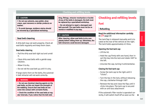 165
165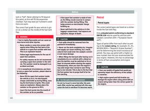 166
166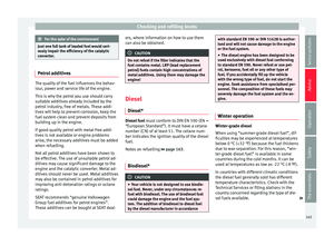 167
167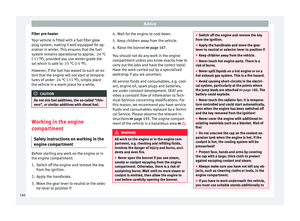 168
168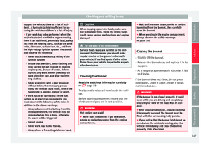 169
169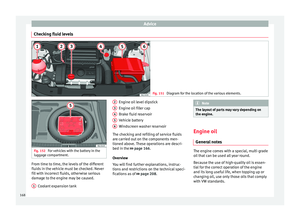 170
170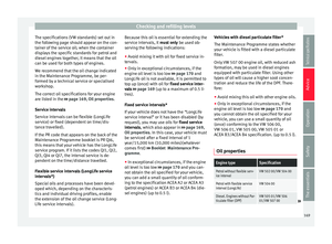 171
171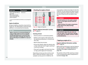 172
172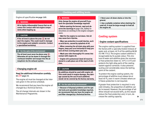 173
173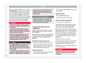 174
174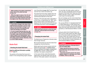 175
175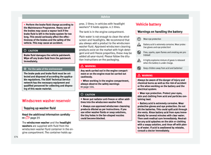 176
176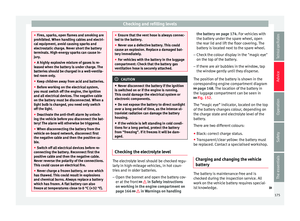 177
177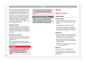 178
178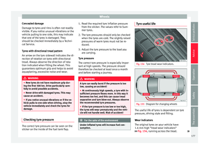 179
179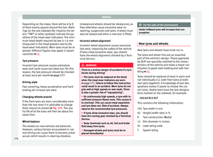 180
180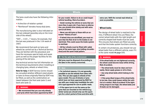 181
181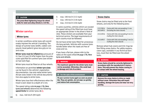 182
182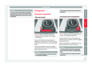 183
183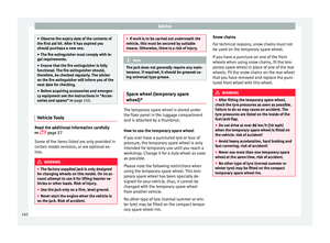 184
184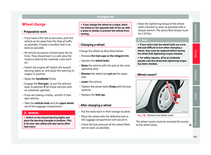 185
185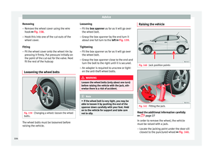 186
186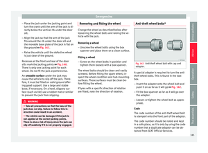 187
187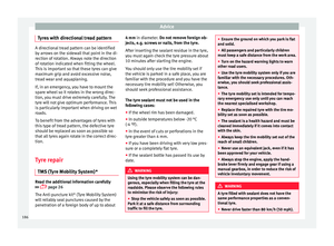 188
188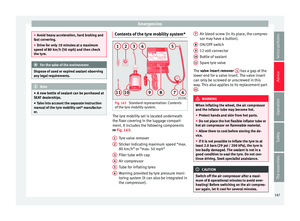 189
189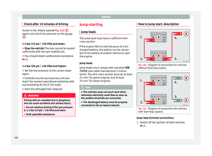 190
190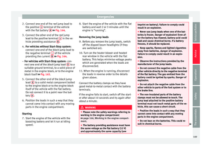 191
191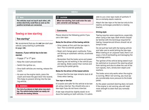 192
192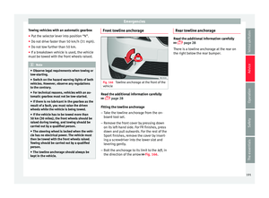 193
193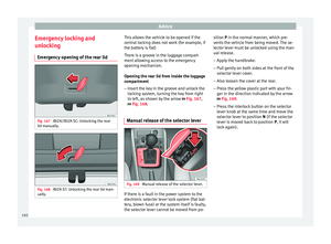 194
194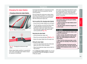 195
195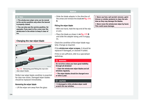 196
196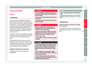 197
197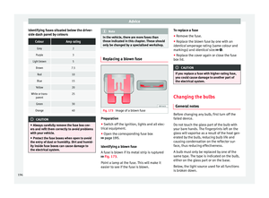 198
198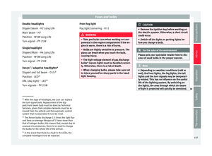 199
199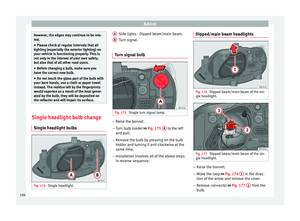 200
200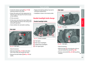 201
201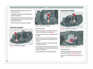 202
202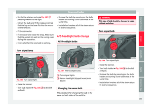 203
203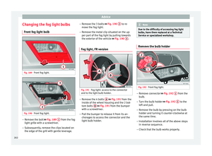 204
204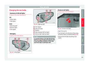 205
205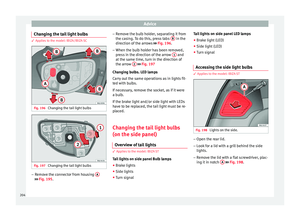 206
206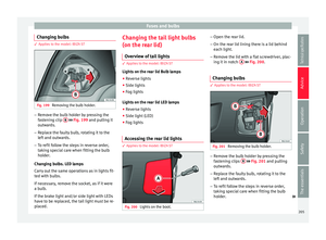 207
207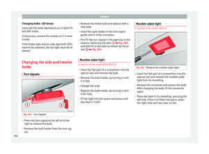 208
208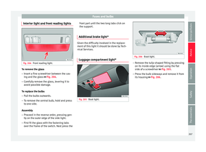 209
209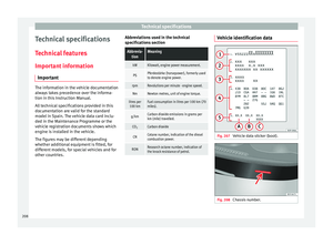 210
210 211
211 212
212 213
213 214
214 215
215 216
216 217
217 218
218 219
219 220
220 221
221 222
222 223
223 224
224 225
225 226
226 227
227 228
228 229
229 230
230 231
231 232
232 233
233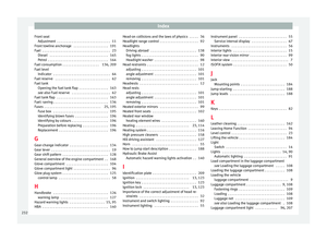 234
234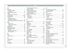 235
235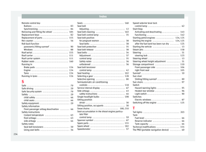 236
236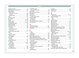 237
237 238
238 239
239