Page 129 of 404
6
Fittings127
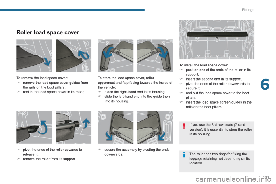
Roller load space cover
To install the load space cover: position one of the ends of the roller in its support, insert the second end in its support, pivot the ends of the roller downwards to secure it, reel out the load space cover to the boot pillars, insert the load space screen guides in the rails on the boot pillars.
To remove the load space cover: remove the load space cover guides from the rails on the boot pillars, reel in the load space cover in its roller,
To store the load space cover, roller uppermost and flap facing towards the inside of the vehicle: place the right-hand end in its housing, slide the left-hand end into the guide then into its housing,
pivot the ends of the roller upwards to release it, remove the roller from its support.
secure the assembly by pivoting the ends downwards. The roller has two rings for fixing the luggage retaining net depending on its location.
If you use the 3 rd row seats (7 seat version), it is essential to store the roller in its housing.
Page 130 of 404
Fittings
128
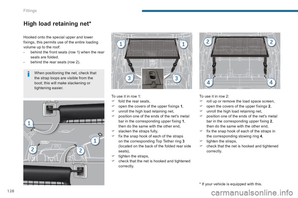
High load retaining net *
To use it in row 1: fold the rear seats, open the covers of the upper fixings 1 , unroll the high load retaining net, position one of the ends of the net's metal bar in the corresponding upper fixing 1 , then do the same with the other end, slacken the straps fully, fix the snap hook of each of the straps on the corresponding Top Tether ring 3(located on the back of the folded rear side seats), tighten the straps, check that the net is hooked and tightened
c o r r e c t l y.
To use it in row 2: roll up or remove the load space screen, open the covers of the upper fixings 2 , unroll the high load retaining net, position one of the ends of the net's metal bar in the corresponding upper fixing 2 , then do the same with the other end, fix the snap hook of each of the straps in the corresponding stowing ring 4 , tighten the straps, check that the net is hooked and tightened c o r r e c t l y.
Hooked onto the special upper and lower fixings, this permits use of the entire loading volume up to the roof: - behind the front seats (row 1) when the rear seats are folded. - behind the rear seats (row 2).
* If your vehicle is equipped with this.
When positioning the net, check that the strap loops are visible from the boot; this will make slackening or tightening easier.
Page 131 of 404
6
Fittings129
Luggage retaining net
Hooked onto the stowing rings on the floor and/or on the load space cover roller, the luggage retaining net available as an accessory enables you to secure your luggage.
There are 4 possible positions:
- flat at the bottom of the boot,
- horizontal, level with the load space cover,
- vertical at the back of the rear seats,
- flat at the bottom of the boot and vertical at the back of the rear seats.
Page 133 of 404
6
Fittings131
Torch
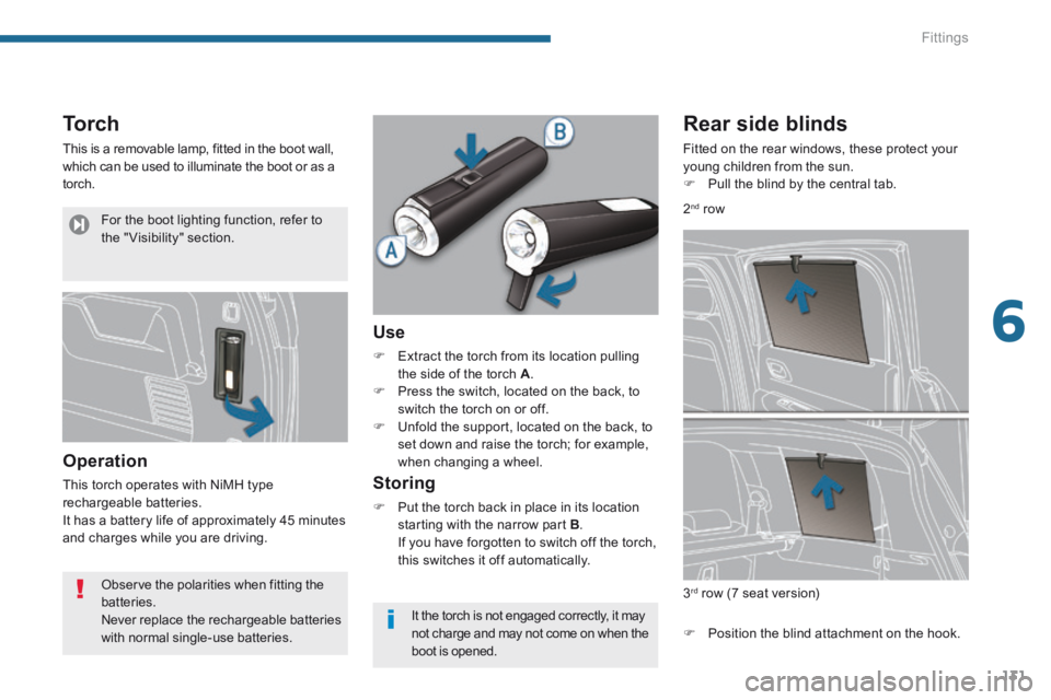
This is a removable lamp, fitted in the boot wall, which can be used to illuminate the boot or as a torch.
Operation
This torch operates with NiMH type rechargeable batteries. It has a battery life of approximately 45 minutes and charges while you are driving.
Use
Extract the torch from its location pulling the side of the torch A . Press the switch, located on the back, to switch the torch on or off. Unfold the support, located on the back, to set down and raise the torch; for example, when changing a wheel.
Storing
Put the torch back in place in its location starting with the narrow part B . If you have forgotten to switch off the torch, this switches it off automatically.
Rear side blinds
Fitted on the rear windows, these protect your young children from the sun. Pull the blind by the central tab.
Position the blind attachment on the hook.
3 rd row (7 seat version)
2nd row
Observe the polarities when fitting the batteries. Never replace the rechargeable batteries with normal single-use batteries.
It the torch is not engaged correctly, it may not charge and may not come on when the
boot is opened.
For the boot lighting function, refer to the " Visibility" section.
Page 162 of 404
Safety
160
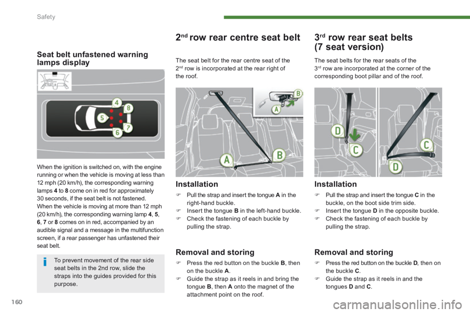
Seat belt unfastened warning lamps display
When the ignition is switched on, with the engine running or when the vehicle is moving at less than 12 mph (20 km/h), the corresponding warning lamps 4 to 8 come on in red for approximately 30 seconds, if the seat belt is not fastened. When the vehicle is moving at more than 12 mph (20 km/h), the corresponding warning lamp 4 , 5,6, 7 or 8 comes on in red, accompanied by an audible signal and a message in the multifunction screen, if a rear passenger has unfastened their seat belt.
2 ndrow rear centre seat belt
Installation
Pull the strap and insert the tongue A in the A in the Aright-hand buckle. Insert the tongue B in the left-hand buckle. Check the fastening of each buckle by pulling the strap.
Removal and storing
Press the red button on the buckle B , then on the buckle A . Guide the strap as it reels in and bring the
tongue B , then A onto the magnet of the attachment point on the roof.
3 rd row rear seat belts
(7 seat version)
Installation
Pull the strap and insert the tongue C in the buckle, on the boot side trim side. Insert the tongue D in the opposite buckle. Check the fastening of each buckle by pulling the strap.
The seat belts for the rear seats of the 3 rd row are incorporated at the corner of the corresponding boot pillar and of the roof.
Removal and storing
Press the red button on the buckle D , then on D , then on Dthe buckle C . Guide the strap as it reels in and the
tongues D and C .
The seat belt for the rear centre seat of the 2 nd row is incorporated at the rear right of the roof.
To prevent movement of the rear side seat belts in the 2nd row, slide the straps into the guides provided for this purpose.
Page 215 of 404
11
Practical information213
Temporary puncture repair kit
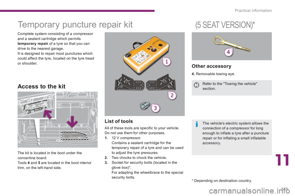
Complete system consisting of a compressor and a sealant cartridge which permits temporary repair of a tyre so that you can temporary repair of a tyre so that you can temporary repairdrive to the nearest garage. It is designed to repair most punctures which could affect the tyre, located on the tyre tread or shoulder.
List of tools
All of these tools are specific to your vehicle.
Do not use them for other purposes. 1. 12 V compressor. Contains a sealant cartridge for the temporary repair of a tyre and can be used to adjust the tyre pressures. 2. Two chocks to chock the vehicle. 3. Socket for security bolts (located in the glove box) * . For adapting the wheelbrace to the special security bolts.
Other accessory
4. Removable towing eye.
Access to the kit
(5 SEAT VERSION) *
The kit is located in the boot under the concertina board. To o l s 4 and 5 are located in the boot interior trim, on the left-hand side.
Refer to the "Towing the vehicle" section.
The vehicle's electric system allows the connection of a compressor for long
enough to inflate a tyre after a puncture repair or for inflating a small inflatable accessory.
* Depending on destination country.
Page 221 of 404
11
Practical information219
Temporary puncture repair kit
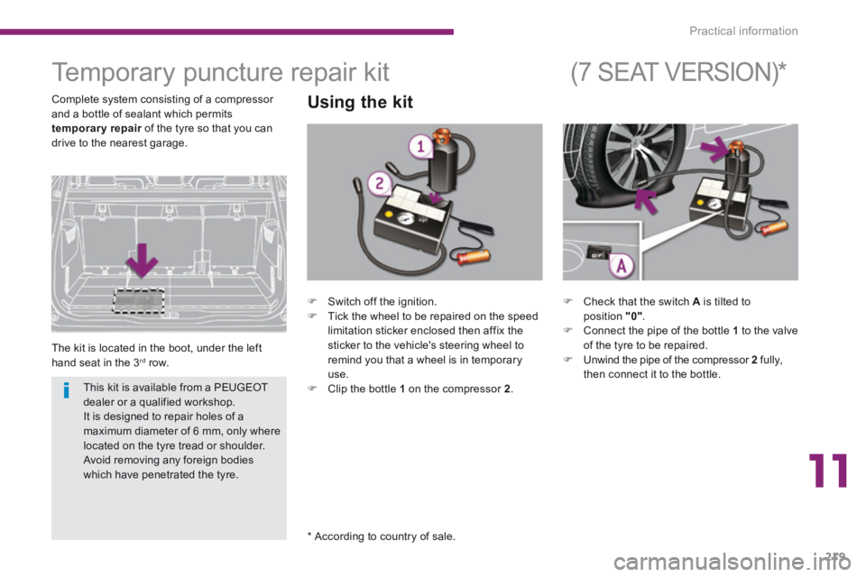
The kit is located in the boot, under the left hand seat in the 3 rd row.
Using the kit
* According to country of sale.
(7 SEAT VERSION) *
Complete system consisting of a compressor and a bottle of sealant which permits temporary repair of the tyre so that you can temporary repair of the tyre so that you can temporary repairdrive to the nearest garage.
Check that the switch A is tilted to position "0" . Connect the pipe of the bottle 1 to the valve of the tyre to be repaired. Unwind the pipe of the compressor 2 fully, then connect it to the bottle.
Switch off the ignition. Tick the wheel to be repaired on the speed limitation sticker enclosed then affix the sticker to the vehicle's steering wheel to remind you that a wheel is in temporary use. Clip the bottle 1 on the compressor 2 . This kit is available from a PEUGEOT dealer or a qualified workshop. It is designed to repair holes of a maximum diameter of 6 mm, only where located on the tyre tread or shoulder. Avoid removing any foreign bodies which have penetrated the tyre.
Page 225 of 404
11
Practical information223
Changing a wheel *
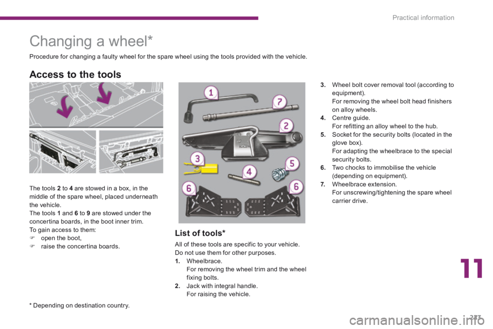
The tools 2 to 4 are stowed in a box, in the middle of the spare wheel, placed underneath the vehicle. The tools 1 and 6 to 9 are stowed under the concertina boards, in the boot inner trim. To gain access to them: open the boot, raise the concertina boards.
Access to the tools
Procedure for changing a faulty wheel for the spare wheel using the tools provided with the vehicle.
List of tools *
All of these tools are specific to your vehicle. Do not use them for other purposes. 1. Wheelbrace. For removing the wheel trim and the wheel fixing bolts. 2. Jack with integral handle. For raising the vehicle.
3. Wheel bolt cover removal tool (according to equipment). For removing the wheel bolt head finishers on alloy wheels. 4. Centre guide. For refitting an alloy wheel to the hub. 5. Socket for the security bolts (located in the glove box). For adapting the wheelbrace to the special security bolts. 6. Two chocks to immobilise the vehicle (depending on equipment). 7. Wheelbrace extension. For unscrewing/tightening the spare wheel carrier drive.
* Depending on destination country.