Page 133 of 256

131
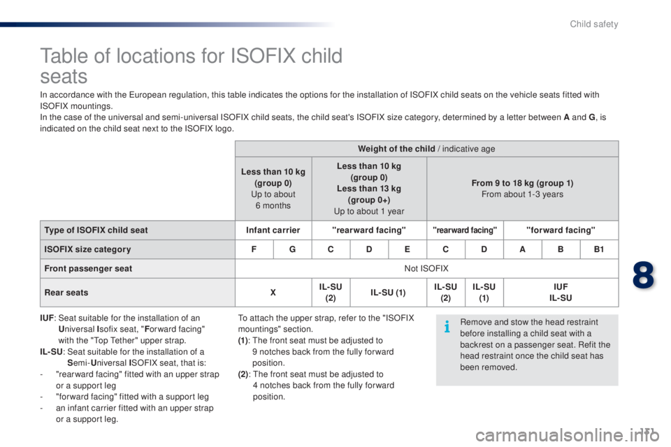
table of locations for ISOFIX child
seats
In accordance with the european regulation, this table indicates the options for the installation of ISOFIX child seats on the vehicle seats fitted with
ISOFIX mountings.
In the case of the universal and semi-universal ISOFIX child seats, the child seat's ISOFIX size category, determined by a letter between A and G , is
indicated on the child seat next to the ISOFIX logo.
IUF :
S
eat suitable for the installation of an
U niversal I sofix seat, " For ward facing"
with the "
to
p t
e
ther" upper strap.
IL- SU :
S
eat suitable for the installation of a
S emi- Universal I SOFIX seat, that is:
-
"
rear ward facing" fitted with an upper strap
or a support leg
-
"
for ward facing" fitted with a support leg
-
a
n infant carrier fitted with an upper strap
or a support leg. Weight of the child / indicative age
Less than 10 kg (group 0)
up t
o about
6
monthsLess than 10 kg
(group 0)
Less than 13 kg (group 0+)
up t
o about 1 yearFrom 9 to 18 kg (group 1)
From about 1-3 years
Type of ISOFIX child seat Infant carrier"rearward facing"
"rearward facing""forward facing"
ISOFIX size categor y F G C D E C D A B B1
Front passenger seat Not ISOFIX
Rear seats XIL- SU
(2) IL- SU
(1) IL- SU
(2) IL- SU
(1) IUF
IL- SU
Remove and stow the head restraint
before installing a child seat with a
backrest on a passenger seat. Refit the
head restraint once the child seat has
been removed.
to a
ttach the upper strap, refer to the "ISOFIX
mountings" section.
(1) :
t
h
e front seat must be adjusted to
9
notches back from the fully for ward
position.
(2):
t
h
e front seat must be adjusted to
4
notches back from the fully for ward
position.
8
Child safety
Page 134 of 256

132
the incorrect installation of a child seat in a
vehicle compromises the child's protection in
the event of an accident.
Check that there is no seat belt or seat belt
buckle under the child seat as this could
destabilise it.
Remember to fasten the seat belts or the
child seat harnesses keeping the slack in
relation to the child's body to a minimum,
even for short journeys.
For the installation of a child seat using a
seat belt, ensure that this is well tensioned
on the child seat and that it is holding the
child seat firmly against the seat of your
vehicle. If your front passenger seat is
adjustable, move it forward if necessary.
At the rear seats, always leave sufficient
space between the front seat and:
-
a r
ear ward facing child seat,
-
t
he feet of a child seated in a for ward
facing child seat.
For this, move the front seat for ward and if
necessary straighten its backrest.
Recommendations on child seats
the chest part of the seat belt must be
positioned on the child's shoulder without
touching the neck.
en
sure that the lap part of the seat belt
passes correctly over the child's thighs.
P
e
uge
Ot
recommends the use of a booster
seat which has a back, fitted with a seat belt
guide at shoulder level.
As a safety precaution, never leave:
-
o
ne or more children alone and
unsupervised in a vehicle,
-
a c
hild or an animal in a vehicle which
is exposed to the sun, with the windows
closed,
-
t
he keys within reach of children inside
the vehicle.
to p
revent accidental opening of the doors,
use the "Child lock".
ta
ke care not to open the rear windows by
more than one third.
to p
rotect young children from the rays of
the sun, fit side blinds on the rear windows.
th
e legislation on carrying a child on the
front passenger seat is specific to each
country. Refer to the legislation in force in
your country.
Deactivate the passenger's front airbag
when a "rear ward facing" child seat is
installed on the front seat. Otherwise, the
child would risk being seriously injured or
killed if the airbag were deployed. For optimum installation of the "forward facing"
child seat, ensure that the back of the child
seat is as close as possible to the backrest of
the vehicle's seat, or in contact if possible.
th
e head restraint must be removed before
installing a child seat with a backrest on the
passenger seat.
en
sure that the head restraint is stowed or
attached securely so that it is not thrown
around the vehicle in the event of sharp
braking.
Refit the head restraint as soon as the child
seat is removed.
Installing a booster
cushion
Children at the front
Child safety
Page 139 of 256
137
F uncoil the pipe stowed under the compressor.
F
C
onnect the pipe from the compressor to
the sealant cartridge.
F
t
u
rn the the sealant cartridge and secure it
in the cut-out provided on the compressor.
Repair procedure
Avoid removing any foreign bodies
which have penetrated into the tyre. F
R
emove the valve cap from the tyre to be
repaired, and place it in a clean area.
F
C
onnect the hose from the sealant
cartridge to the valve of the tyre to be
repaired and tighten firmly.
F
S
witch off the ignition.
F
S
ecure the speed limit sticker inside the
vehicle.
9
Practical information
Page 140 of 256

138
F Check that the compressor switch is at the "O " position).
F
u
n
coil fully the electric cable, stowed under
the compressor.
F
C
onnect compressor's plug to the vehicle's
12 V socket.
F
S
witch on the ignition.
ta
ke care, the sealant product
is harmful (e.g. ethylene-glycol,
colophony...) if swallowed and causes
irritation to the eyes.
Keep this product out of the reach of
children.
th
e use-by date is marked on the
cartridge.
After use, do not discard the
cartridge by the roadside, take it to a
P
e
uge
Ot
dealer or an authorised
waste disposal site.
Don't forget to obtain a new sealant
cartridge, available from a P
e
uge
Ot
dealer or a qualified workshop. If after around 5 to 7 minutes the
pressure is not attained, this indicates
that the tyre is not repairable; contact
a P
e
uge
Ot
dealer or a qualified
workshop for assistance.
F S tart the compressor by placing the switch
at the " I" position and leave it running until
the tyre pressure reaches 2.0 bar.
t
h
e sealant product is injected into the tyre
under pressure; do not disconnect the pipe
from the valve during this operation (risk of
splashing and stains).
Practical information
Page 141 of 256
139
F Place the switch in the "O" position.
F R emove the kit.
F
D
rive immediately for approximately
three miles (five kilometres), at reduced
speed (between 15 and 35 mph (20 and
60
km/h)), to plug the puncture.
F
S
top to check the repair and the tyre
pressure using the kit.
Checking / adjusting tyre pressures
F Check that the compressor switch is at the "O " position.
F
u
n
coil fully the electric cable, stowed under
the compressor.
F
C
onnect the compressor's plug to the
vehicle's 12 V socket.
F
S
witch on the ignition.
You can also use the compressor, without
injecting sealant, to check and if necessary
adjust the tyre pressures
F
R
emove the valve cap from the tyre and
place it in a clean area.
F
u
n
coil the pipe stowed under the
compressor.
F
S
crew the pipe onto the valve and tighten
f i r m l y.
9
Practical information
Page 142 of 256
140
Should the pressure of one or more
tyres be adjusted, it is necessary to
reinitialise the under-inflation detection
system.
Refer to the "
un
der-inflation detection"
section.
Tyre under-inflation
detection
After repair of the tyre, the warning
lamp will remain on until the system is
reinitialised.
For more information, refer to the
"
un
der-inflation detection" section.
F
S
tart the compressor by placing the switch
at the " I" position and adjust the pressure
to the value shown on the vehicle's tyre
pressure label.
t
o d
eflate: press the black button on the
compressor pipe, at the valve connector.
F
O
nce the correct pressure is reached, put
the switch to the " O" position.
F
R
emove the kit then stow it.
Practical information
Page 144 of 256
142
Access to the spare wheel
and tools
Tools provided
the following tools are installed in a carrier,
located in the centre of the spare wheel:
1.
Wheelbrace
2.
J
ack with handle
3.
R
emovable towing eye.
R
efer to the "
to
wing the vehicle" section.
Tyre pressures
these are indicated on the label affixed to the
middle pillar of the left door, driver's side.
Refer to the "Identification markings" section.All of these tools are specific to your
vehicle and can vary according to
equipment. Do not use them for any
other purposes.
Never go underneath a vehicle
supported only by a jack (use an axle
stand).
Do not use:
-
t
he jack for anything other than
lifting the vehicle,
-
a
ny other jack than the one
provided by the manufacturer.
Depending on version, the spare wheel and
tools are stowed in the boot under the floor.
F
R
emove the boot carpet.
F
R
emove the tool carrier.
F
S
lacken the central wheel retaining bolt.
F
R
emove the wheel.
Practical information
Page 149 of 256

147
Changing a bulb
Front lamps
1. Sidelamps (LEDs*).
2. Direction indicators (PY21W amber).
3.
D
ipped beam / Main beam headlamps
(HiR2-55W).
4.
F
ront foglamps.
5.
D
aytime running lamps (LEDs*). In some weather conditions (e.g. low
temperature or humidity), the presence
of misting on the internal sur face of the
glass of the headlamps and rear lamps
is normal; it disappears after the lamps
have been on for a few minutes.
th
e headlamps are fitted with
polycarbonate glass with a protective
coating:
F
d
o not clean them using a dr y
or abrasive cloth, nor with a
detergent or solvent product,
F
u
se a sponge and soapy water or a
pH neutral product,
F
w
hen using a high pressure washer
on persistent marks, do not keep
the lance directed towards the
lamps or their edges for too long,
so as not to damage their protective
coating and seals.
Changing a bulb should only be done
after the headlamp has been switched
off for several minutes (risk of serious
burns).
F
D
o not touch the bulb directly with
your fingers, use a lint-free cloth.
It is imperative to use only anti-
ultraviolet (
uV
) type bulbs to avoid
damaging the headlamp.
Always replace a failed bulb with a
new bulb with the same type and
specification.
* L
eD
: light-emitting diode.
9
Practical information