Page 111 of 256

109
the tRC and DSC systems offer
increased safety in normal driving, but
should not encourage the driver to take
extra risks or drive at high speed.
th
e correct operation of these
systems depends on observation of
the manufacturer's recommendations
regarding the wheels (tyres and rims),
the braking components, the electronic
components and the assembly and
repair procedures used by P
e
uge
Ot
dealers.
After an impact, have the system
checked by a P
e
uge
Ot
dealer or a
qualified workshop.
Deactivation
In exceptional conditions (starting a vehicle
which is bogged down, stuck in snow, on soft
ground...), it may be advisable to deactivate
the DSC system, so that the wheels can move
freely and regain grip.
Operating fault
However, it is recommended that the system be
reactivated as soon as possible.
F
P
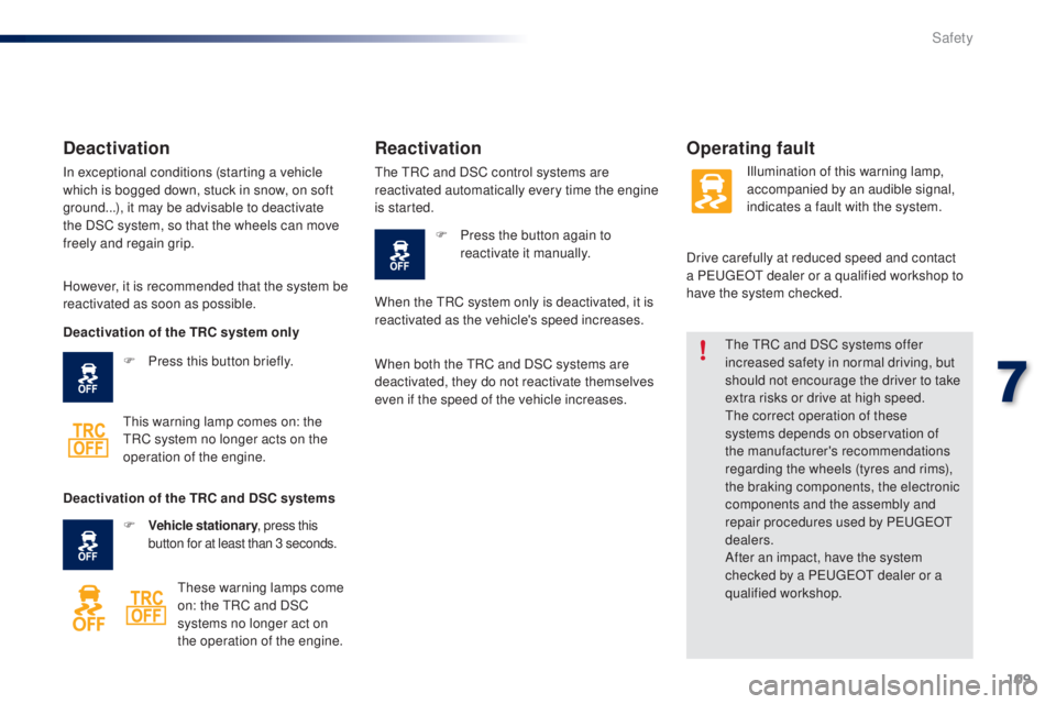
ress this button briefly.
th
is warning lamp comes on: the
tR
C system no longer acts on the
operation of the engine.
Reactivation
the tRC and DSC control systems are
reactivated automatically every time the engine
is started.
F
P
ress the button again to
reactivate it manually. Illumination of this warning lamp,
accompanied by an audible signal,
indicates a fault with the system.
Drive carefully at reduced speed and contact
a P
e
uge
Ot
dealer or a qualified workshop to
have the system checked.
Deactivation of the TRC system only
Deactivation of the TRC and DSC systems F
V
ehicle stationary , press this
button for at least than 3 seconds.
th
ese warning lamps come
on: the
t
R
C and DSC
systems no longer act on
the operation of the engine. When the
t
R
C system only is deactivated, it is
reactivated as the vehicle's speed increases.
When both the
t
R
C and DSC systems are
deactivated, they do not reactivate themselves
even if the speed of the vehicle increases.
7
Safety
Page 115 of 256

113
Airbags
System designed to contribute towards the
safety of the occupants in the event of violent
collisions. t
h
e airbags supplement the action
of the force-limiting seat belts.
If a collision occurs, the electronic detectors
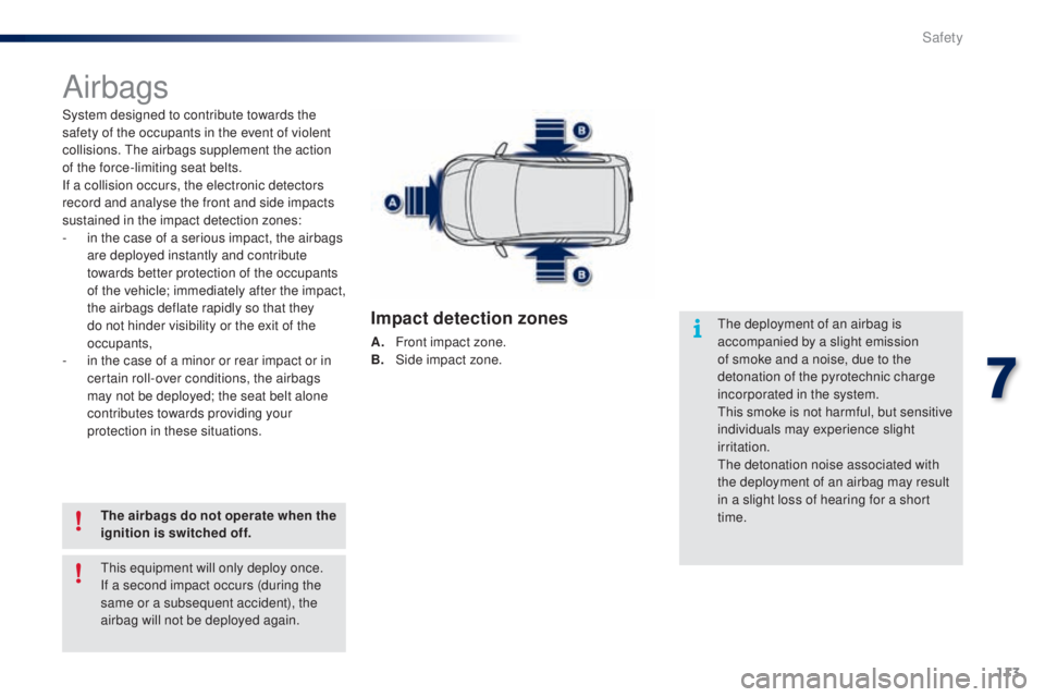
record and analyse the front and side impacts
sustained in the impact detection zones:
-
i
n the case of a serious impact, the airbags
are deployed instantly and contribute
towards better protection of the occupants
of the vehicle; immediately after the impact,
the airbags deflate rapidly so that they
do not hinder visibility or the exit of the
occupants,
-
i
n the case of a minor or rear impact or in
certain roll-over conditions, the airbags
may not be deployed; the seat belt alone
contributes towards providing your
protection in these situations.
The airbags do not operate when the
ignition is switched off.
th
e deployment of an airbag is
accompanied by a slight emission
of smoke and a noise, due to the
detonation of the pyrotechnic charge
incorporated in the system.
th
is smoke is not harmful, but sensitive
individuals may experience slight
irritation.
th
e detonation noise associated with
the deployment of an airbag may result
in a slight loss of hearing for a short
time.
th
is equipment will only deploy once.
If a second impact occurs (during the
same or a subsequent accident), the
airbag will not be deployed again.
Impact detection zones
A. Front impact zone.
B. S ide impact zone.
7
Safety
Page 136 of 256

134
Fuel tank
Low fuel levelRefuelling
When the low fuel level is reached,
this warning lamp comes on and the
last bar flashes, accompanied by an
audible signal.
You have approximately 5 litres remaining.
In certain driving conditions and depending on
the engine, the distance which can be travelled
with the fuel remaining may be less than
30
miles (50 km).
When the frequency of the flashing increases,
you have approximately 3 litres remaining .
to r
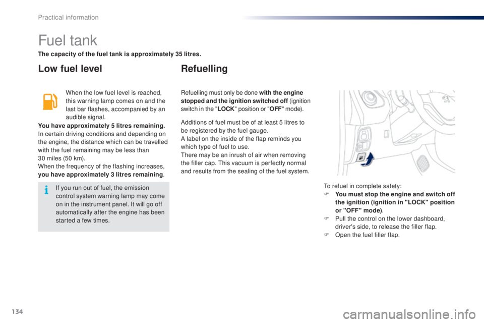
efuel in complete safety:
F
Y
ou must stop the engine and switch off
the ignition (ignition in "LOCK" position
or "OFF" mode) .
F
P
ull the control on the lower dashboard,
driver's side, to release the filler flap.
F
O
pen the fuel filler flap.
If you run out of fuel, the emission
control system warning lamp may come
on in the instrument panel. It will go off
automatically after the engine has been
started a few times. Refuelling must only be done with the engine
stopped and the ignition switched off
(ignition
switch in the " LOCK" position or " OFF" m o d e).
The capacity of the fuel tank is approximately 35 litres.
Additions of fuel must be of at least 5 litres to
be registered by the fuel gauge.
A label on the inside of the flap reminds you
which type of fuel to use.
th
ere may be an inrush of air when removing
the filler cap.
t
h
is vacuum is per fectly normal
and results from the sealing of the fuel system.
Practical information
Page 155 of 256

153
Before changing a fuse, it is necessary to
F i mmobilise the vehicle and switch off the
ignition,
F
s
witch off all electrical consumers,
F
i
dentify the failed fuse using the fuse
allocation tables and diagrams in the
following pages,
F
i
dentify and correct the cause of the
problem.
Replacing a fuse
Good Failed
Tw e e z e r
When replacing a fuse, you must always:
F
u
se the special tweezer to extract the fuse
from its holder and check the condition of
its element,
F
r
eplace a failed fuse by on of the same
rating (same colour); the use of a different
rating fuse could cause a fault (risk of fire).
If the problem recurs after replacing the fuse,
have the vehicle's electrical system checked by
P
e
uge
Ot
dealer or a qualified workshop. P
e
uge
Ot
will not accept any
responsibility for the costs incurred
in repairing your vehicle or for the
malfunctions resulting from the
installation of auxiliary accessories which
were not supplied or recommended by
P
e
uge
Ot
and which were not installed
in accordance with its instructions, in
particular where the current consumption
of all the the additional equipment
connected exceeds 10 milliamps.
Installation of electrical
accessories
Your vehicle's electrical system is
designed to operate with standard or
optional equipment.
Before installing other electrical
equipment or accessories on your
vehicle, contact a P
e
uge
Ot
dealer or
a qualified workshop.
9
Practical information
Page 156 of 256
154
Dashboard fuses
the fusebox is located below the dashboard
(driver's side).
F u
n
clip the plastic cover for access to the
fuses.
When you have finished, carefully refit the
c ove r. Fuse
N° Rating
(A) Functions
1 5Fuel injection system - Audio system - VSC system
2 15Front and rear screenwash
3 5Main distribution unit - Instrument panel - Display screen -
Air conditioning - Heated rear screen and door mirror heating -
Heated seats - e
l
ectric fabric roof - Audio system
4 5
el
ectric power steering - Stop & Start
5 15Rear wiper
6 5Cooling fan - ABS system
e
S
P - VSC system
7 25Front wiper
8 10Heated door mirrors
9 1512 V socket (120 W max)
10 7. 5Door mirrors - Audio system - Stop & Start - Instrument panel -
Display screen
Practical information
Page 157 of 256
155
FuseN° Rating
(A) Functions
11 5Steering lock - Fuel injection system -
e
l
ectronic gearbox
12 7. 5Airbags
13 5Instrument panel - Display Screen - Stop & Start
14 15* *
Steering - Fuel injection system - Brake lamps
7. 5 *
15 7. 5 * *
Fuel injection system - Stop & Start
10*
16 7. 5
en
gine diagnosis
17 10Brake lamps -
t
h
ird brake lamp - Fuel injection system - ABS
system - VSC system -
e
l
ectronic gearbox - Keyless e
n
try and
Starting system
18 10Sidelamps - Number plate lamps - Rear foglamp - Front
foglamps - Rear lamps - Lighting dimmer
19 40Air conditioning
* V
ti 8
2 engine.
** V
ti 6
8 engine.
9
Practical information
Page 158 of 256
156
FuseN° Rating
(A) Functions
20 40Air conditioning -
e
n
gine self-diagnosis - Sidelamps - Number
plate lamps - Rear foglamp - Front foglamps - Rear lamps
-
Lighting dimmer - Brake lamps -
t
h
ird brake lamp - Fuel
injection system - ABS system - VSC system -
e
l
ectronic
gearbox - "Keyless
e
n
try and Starting" system - e
l
ectric
windows
21 30Fuel injection system - Stop & Start - Main distribution unit
22** 7, 5Fuel injection system
23** 20Fuel injection system - Stop & Start
24 25Main distribution unit
25 30
el
ectric windows
26 25
el
ectric windows
27 10Air conditioning
28 5Rear foglamp
** V
ti 6
8 engine.
Practical information
Page 159 of 256
157
Fuse
N° Rating
(A) Functions
1 10Right hand dipped beam
2 10Left hand dipped beam - Headlamp adjustment
3 7. 5Right hand main beam
4 7. 5Left hand main beam
5* 15Fuel injection system
6* 7. 5Fuel injection system
7* 15Fuel injection system
8* 7. 5Cooling fan
9 7. 5Air conditioning
10* * 7. 5Fuel injection system - Brake lamps -
t
h
ird brake lamp
11 5Courtesy lamp - Boot lamp
12 10
Direction indicators - Hazard warning lamps - Instrument panel - Display screen
Fuses under the bonnet
F unclip the plastic cover, located below
the windscreen, by pressing on the
two
catches.
F
u
n
clip the fusebox cover by pressing on
the lug on the right, for access to the fuses.
When you have finished, carefully refit the
c ove r.
* V
ti 8
2 engine.
** V
ti 6
8 engine.
9
Practical information