Page 10 of 372
1. Engine hood (P. 3-24)
2. Windshield wiper and washer switch(P. 2-19)
3. Windshield (P. 8-17)
4. Power windows (P. 2-33)
5. Fuel-filler door, fuel-filler cap, fuel rec-
ommendation (P. 3-26, 3-27, 9-22)
6. Door locks, NISSAN Intelligent Key®
(if so equipped) , keys (P. 3-5, 3-3, 3-2)
7. Mirrors, side camera (if so equipped)
(P. 3-30, 4-15)
8. Tire pressure (P. 8-29)
9. Flat tire (P. 6-3)
10. Tire chains (P. 8-36)
11. Headlight and turn signal switch
(P. 2-21)
12. Replacing bulbs (P. 8-24)
13. Fog light switch (if so equipped)
(P. 2-21)
14. Front camera (if so equipped) (P. 4-15)
See the page number indicated in paren-
theses for operating details.
LII2071
EXTERIOR FRONT
Illustrated table of contents0-3
Page 13 of 372
/turnsignal switch (P. 2-21)
2. Driver’s supplemental air bag/horn
(P. 1-39, 2-23)
3. Meters and gauges (P. 2-3) 4. Windshield wiper/washer switch
(P. 2-19, 2-")
1. Headlight/fog light (if so equipped)/turnsignal switch (P. 2-21)
2. Driver’s supplemental air bag/horn
(P. 1-39, 2-23)
3. Meters and gauges (P. 2-3) 4. Windshield wiper/washer switch
(P. 2-19, 2-20)
5. Center ventilator (P. 4-20)
6. Defroster switch (P. 2-20)
7. Hazard warning flasher switch (P. 6-2)
8. Climate control (P. 4-21) 9. Audio system (if so equipped) (P. 4-29)
10. Upper glove box (P. 2-29)
11. Passenger’s supplemental air bag
(P. 1-39)
12. Side ventilator (P. 4-20)
13. Outside mirror control switch (P. 3-30)
14. Vehicle Dynamic Control (VDC) off
switch (P. 2-25)
15. Fuel-filler lid release lever (P. 3-26)
16. Hood release lever (P. 3-24)
17. Tilt steering (P. 3-29)
18. Ignition switch (P. 5-8)
19. Cup holders (P. 2-28)
20. Shift lever (P. 5-15)
21. Upper glove box release handle
(P. 2-29)
22. Lower glove box (P. 2-30)
*:Refer to the separate Navigation System Own-
er’s Manual (if so equipped) .
See the page number indicated in paren-
theses for operating details.
LIC2533
INSTRUMENT PANEL
0-6Illustrated table of contents
Page 15 of 372
Warninglight Name Page
or
Anti-lock Braking
System (ABS) warn-
ing light 2-10
or
Brake warning light 2-10
Charge warning light 2-11
Door open warning
light
2-11
Engine oil pressure
warning light2-11
Low fuel warning
light2-11
Warning
light Name Page
Low tire pressure
warning light (if so
equipped) 2-11
NISSAN Intelligent
Key ® warning light
(if so equipped)2-13
Power steering
warning light
2-13
Seat belt warning
light and chime2-14
Shift P warning light
(if so equipped)2-13
Supplemental air
bag warning light2-14
Indicator
light Name Page
Continuously Vari-
able Transmission
(CVT) position indi-
cator light (if so
equipped) 2-14
Cruise main switch
indicator light (if so
equipped)
2-14
Engine start opera-
tion indicator (if so
equipped)2-14
Front fog light indi-
cator light (if so
equipped)2-15
Front passenger air
bag status light
2-15
High beam indicator
light (blue)2-15
WARNING/INDICATOR LIGHTS
0-8Illustrated table of contents
Page 74 of 372

2 Instruments and controls
Instrument panel...................................2-2
Meters and gauges ................................2-3
Speedometer and odometer . . ...................2-3
Tachometer ....................................2-5
Engine coolant temperature gauge ...............2-6
Fuel gauge ....................................2-6
Trip computer ..................................2-7
Service interval reminder (if so equipped) .........2-8
Warning/indicator lights and audible reminders .......2-9
Checking bulbs ............................... 2-10
Warning lights ................................ 2-10
Indicator lights ................................ 2-14
Audible reminders ............................. 2-17
Security systems ................................. 2-17
NISSAN vehicle immobilizer system
(if so equipped) ............................... 2-17
Windshield wiper and washer switch ...............2-19
Switch operation .............................. 2-19
Rear window wiper and washer switch ..............2-20
Rear window and outside mirror defroster switch .....2-20
Headlight and turn signal switch. . ..................2-21
Headlight control switch ........................ 2-21
Daytime running light system (Canada only) . . ....2-22 Instrument brightness control
...................2-22
Turn signal switch ............................. 2-23
Fog light switch (if so equipped) ................2-23
Horn ............................................ 2-23
Heated seats (if so equipped) ......................2-24
Vehicle Dynamic Control (VDC) off switch ...........2-25
Power outlet ..................................... 2-26
Storage ......................................... 2-27
Map pockets .................................. 2-27
Seatback pockets ............................. 2-27
Storage trays ................................. 2-28
Cup holders . . . ............................... 2-28
Glove box .................................... 2-29
Cargo cover (if so equipped) ....................2-30
Divide-n-hide adjustable floor
(if so equipped) ............................... 2-31
Grocery
hooks................................ 2-32
Windows ........................................ 2-33
Power windows (if so equipped) ................2-33
Manual windows (if so equipped) ................2-35
Interior light ...................................... 2-36
Map light (if so equipped) ......................... 2-37
Luggage compartment light ........................2-37
Page 75 of 372
/turnsignal switch (P. 2-21)
2. Driver’s supplemental air bag/horn
(P. 1-39, 2-23)
3. Meters and gauges (P. 2-3) 4. Windshield wiper/washer switch
(P. 2-19, 2-")
1. Headlight/fog light (if so equipped)/turnsignal switch (P. 2-21)
2. Driver’s supplemental air bag/horn
(P. 1-39, 2-23)
3. Meters and gauges (P. 2-3) 4. Windshield wiper/washer switch
(P. 2-19, 2-20)
5. Center ventilator (P. 4-20)
6. Defroster switch (P. 2-20)
7. Hazard warning flasher switch (P. 6-2)
8. Climate control (P. 4-21) 9. Audio system (if so equipped) (P. 4-29)
10. Upper glove box (P. 2-29)
11. Passenger’s supplemental air bag
(P. 1-39)
12. Side ventilator (P. 4-20)
13. Outside mirror control switch (P. 3-30)
14. Vehicle Dynamic Control (VDC) off
switch (P. 2-25)
15. Fuel-filler lid release lever (P. 3-26)
16. Hood release lever (P. 3-24)
17. Tilt steering (P. 3-29)
18. Ignition switch (P. 5-8)
19. Cup holders (P. 2-28)
20. Shift lever (P. 5-15)
21. Upper glove box release handle
(P. 2-29)
22. Lower glove box (P. 2-30)
*:Refer to the separate Navigation System Own-
er’s Manual (if so equipped) .
See the page number indicated in paren-
theses for operating details.
LIC2533
INSTRUMENT PANEL
2-2Instruments and controls
Page 76 of 372
1. Tachometer
2. Temperature gauge
3. Odometer/twin trip odometer/tripcomputer
4. Fuel gauge
5. Speedometer 6. Trip odometer reset switch/trip
computer mode
7. Continuously Variable Transmission
(CVT) / Manual Transmission shift
indicator position indicator
8. Instrument brightness control
SPEEDOMETER AND ODOMETER
Speedometer
The speedometer indicates the vehicle speed.
LIC2146
LIC2136
METERS AND GAUGES
Instruments and controls2-3
Page 77 of 372
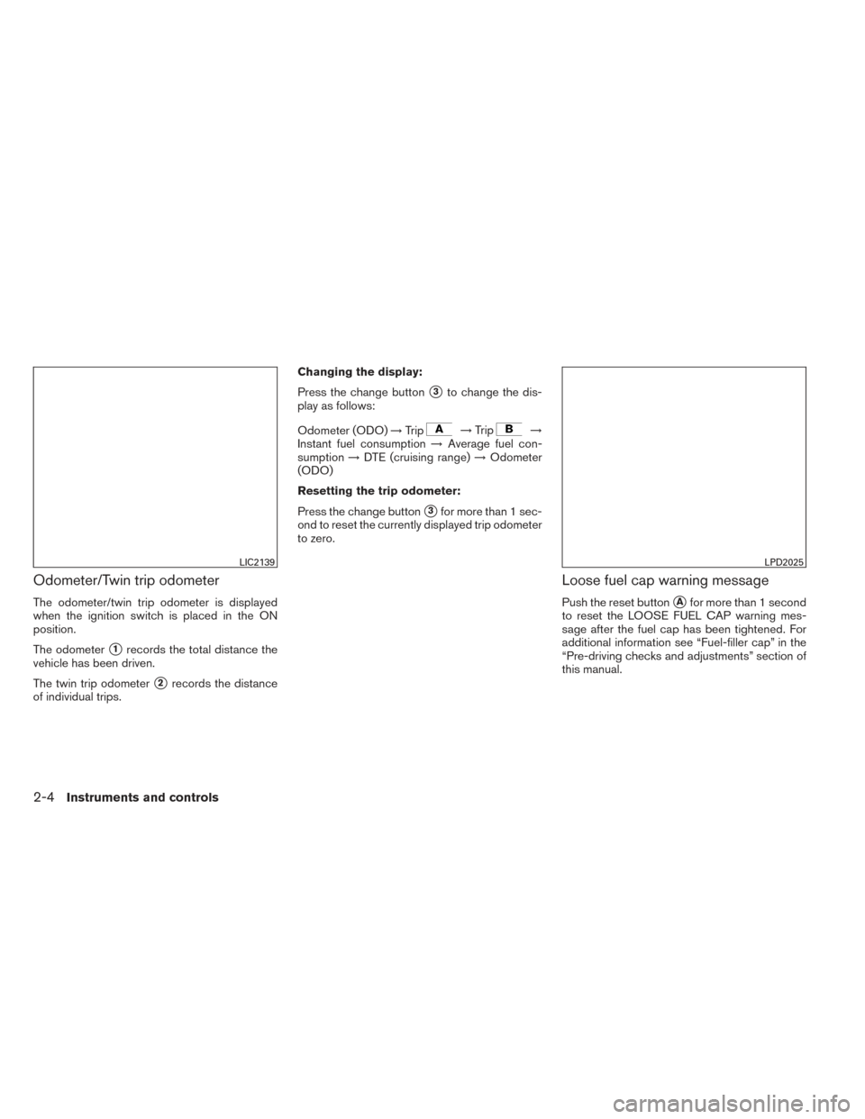
Odometer/Twin trip odometer
The odometer/twin trip odometer is displayed
when the ignition switch is placed in the ON
position.
The odometer
�1records the total distance the
vehicle has been driven.
The twin trip odometer
�2records the distance
of individual trips. Changing the display:
Press the change button
�3to change the dis-
play as follows:
Odometer (ODO) →Trip
→Trip→
Instant fuel consumption →Average fuel con-
sumption →DTE (cruising range) →Odometer
(ODO)
Resetting the trip odometer:
Press the change button
�3for more than 1 sec-
ond to reset the currently displayed trip odometer
to zero.
Loose fuel cap warning message
Push the reset button�Afor more than 1 second
to reset the LOOSE FUEL CAP warning mes-
sage after the fuel cap has been tightened. For
additional information see “Fuel-filler cap” in the
“Pre-driving checks and adjustments” section of
this manual.
LIC2139LPD2025
2-4Instruments and controls
Page 79 of 372

ENGINE COOLANT TEMPERATURE
GAUGE
NOTE:
The ignition switch must be placed in the
ON position for the gauge to give a reading.
The gauge indicates the engine coolant tempera-
ture. The engine coolant temperature will vary
with the outside air temperature and driving con-
ditions.
CAUTION
If the gauge indicates a coolant tempera-
ture near the hot (H) end of the normal
range, reduce vehicle speed to decrease
the temperature. If the gauge is over the
normal range, stop the vehicle as soon as
safely possible. If the engine is over-
heated, continued operation of the vehicle
may seriously damage the engine. See “If
your vehicle overheats” in the “In case of
emergency” section for immediate action
required.
FUEL GAUGE
The gauge indicates�Atheapproximate fuel
level in the tank when the ignition switch is placed
in the ON position.
The gauge may move slightly during braking,
turning, acceleration, or going up or down hills.
The low fuel warning light will turn on when the
amount of fuel in the tank is getting low.
Refill the fuel tank before the gauge regis-
ters E (Empty) .
The
indicates that the fuel-filler door is
located on the driver’s side of the vehicle.
LIC2501LIC2287
2-6Instruments and controls

2. Windshield wiper and washer switch(P. 2-19)
3. Windshield (P. 8-17)
4. Power windows (P. 2-33)
5. Fuel-filler door, fuel-filler cap, fuel rec-
ommendation (P. 3-26, 3-27, 9")
 warn-
ing light 2-10
or
Brake warning light 2-10
Charge warning light 2-11
Door open warning
light
2-11
Engine oil pressure
warning light2-11
L")
")