2014 NISSAN TEANA wiring diagram
[x] Cancel search: wiring diagramPage 2367 of 4801
FRONT FOG LAMP CIRCUITEXL-101
< DTC/CIRCUIT DIAGNOSIS >
C
D E
F
G H
I
J
K
M A
B
EXL
N
O P
FRONT FOG LAMP CIRCUIT
DescriptionINFOID:0000000009463591
The IPDM E/R (intelligent power di stribution module engine room) controls the front fog lamp relay based on
inputs from the BCM over the CAN communication lines . When the front fog lamp relay is energized, power
flows from the front fog lamp relay in the IPDM E/R to the front fog lamps.
Component Function CheckINFOID:0000000009463592
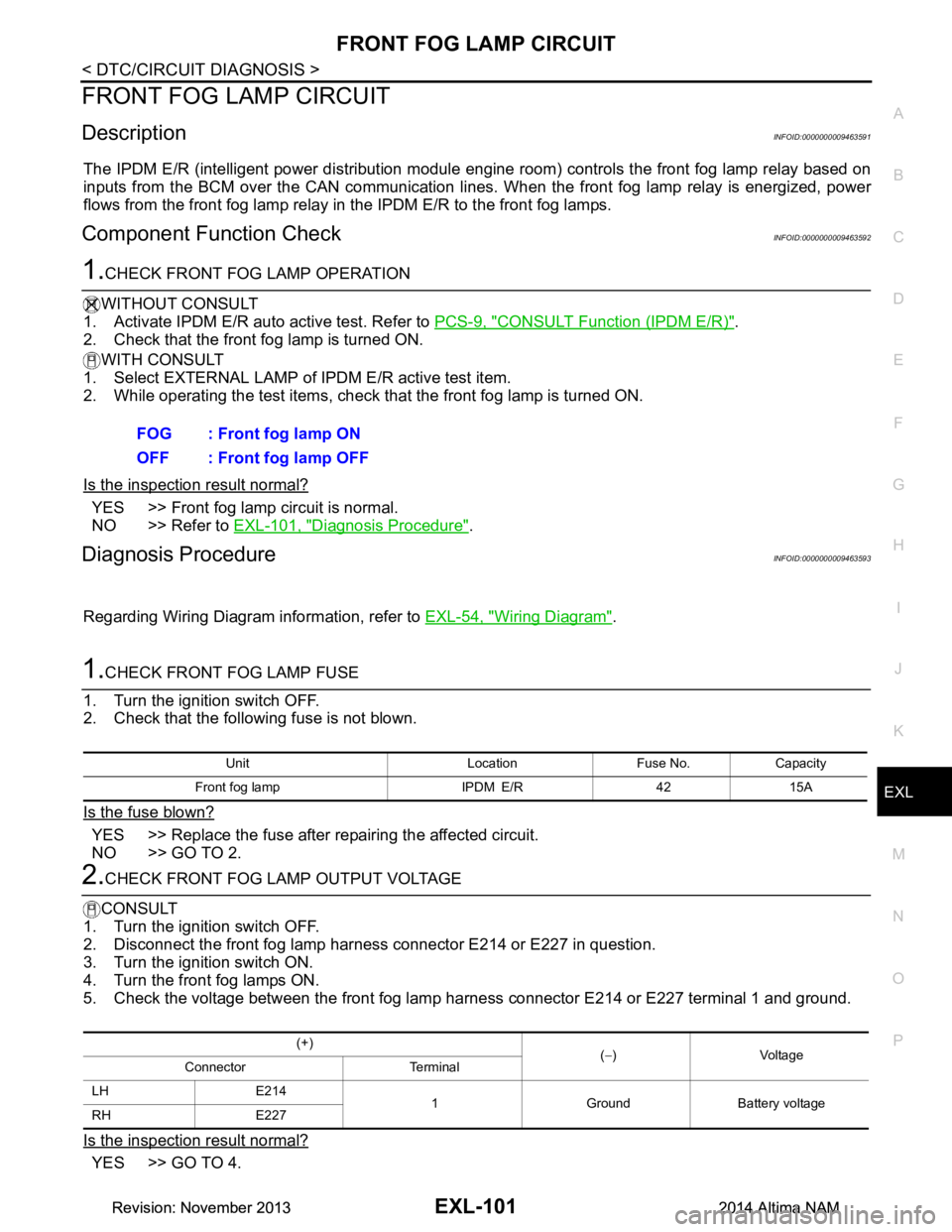
1.CHECK FRONT FOG LAMP OPERATION
WITHOUT CONSULT
1. Activate IPDM E/R auto active test. Refer to PCS-9, "CONSULT Function (IPDM E/R)"
.
2. Check that the front fog lamp is turned ON.
WITH CONSULT
1. Select EXTERNAL LAMP of IP DM E/R active test item.
2. While operating the test items, check that the front fog lamp is turned ON.
Is the inspection result normal?
YES >> Front fog lamp circuit is normal.
NO >> Refer to EXL-101, "Diagnosis Procedure"
.
Diagnosis ProcedureINFOID:0000000009463593
Regarding Wiring Diagram information, refer to EXL-54, "Wiring Diagram".
1.CHECK FRONT FOG LAMP FUSE
1. Turn the ignition switch OFF.
2. Check that the following fuse is not blown.
Is the fuse blown?
YES >> Replace the fuse after repairing the affected circuit.
NO >> GO TO 2.
2.CHECK FRONT FOG LAMP OUTPUT VOLTAGE
CONSULT
1. Turn the ignition switch OFF.
2. Disconnect the front fog lamp harness connector E214 or E227 in question.
3. Turn the ignition switch ON.
4. Turn the front fog lamps ON.
5. Check the voltage between the front fog lamp harness connector E214 or E227 terminal 1 and ground.
Is the inspection result normal?
YES >> GO TO 4. FOG : Front fog lamp ON
OFF : Front fog lamp OFF
Unit Location Fuse No. Capacity
Front fog lamp IPDM E/R 42 15A
(+) (− )Voltage
Connector Terminal
LH E214 1 Ground Battery voltage
RH E227
Revision: November 20132014 Altima NAMRevision: November 20132014 Altima NAM
Page 2369 of 4801
PARKING LAMP CIRCUITEXL-103
< DTC/CIRCUIT DIAGNOSIS >
C
D E
F
G H
I
J
K
M A
B
EXL
N
O P
PARKING LAMP CIRCUIT
DescriptionINFOID:0000000009463594
The IPDM E/R (intelligent power distribution module engi ne room) controls the tail lamp relay based on inputs
from the BCM over the CAN communication lines. When t he tail lamp relay is energized, power flows through
fuses 51 and 52, located in the IPDM E/R. Power then fl ows to the front and rear combination lamps, license
plate lamps.
Component Function CheckINFOID:0000000009463595
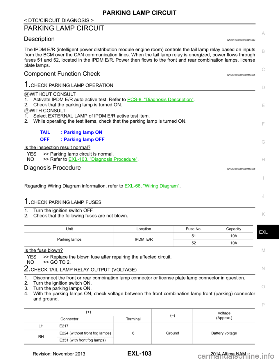
1.CHECK PARKING LAMP OPERATION
WITHOUT CONSULT
1. Activate IPDM E/R auto active test. Refer to PCS-8, "Diagnosis Description"
.
2. Check that the parking lamp is turned ON.
WITH CONSULT
1. Select EXTERNAL LAMP of IP DM E/R active test item.
2. While operating the test items, check that the parking lamp is turned ON.
Is the inspection result normal?
YES >> Parking lamp circuit is normal.
NO >> Refer to EXL-103, "Diagnosis Procedure"
.
Diagnosis ProcedureINFOID:0000000009463596
Regarding Wiring Diagram information, refer to EXL-68, "Wiring Diagram".
1.CHECK PARKING LAMP FUSES
1. Turn the ignition switch OFF.
2. Check that the following fuses are not blown.
Is the fuse blown?
YES >> Replace the blown fuse after repairing the affected circuit.
NO >> GO TO 2.
2.CHECK TAIL LAMP RELAY OUTPUT (VOLTAGE)
1. Disconnect the front or rear combination lamp connector or license plate lamp connector in question.
2. Turn the ignition switch ON.
3. Turn the parking lamps ON.
4. With the parking lamps ON, check voltage between t he front combination lamp front (parking) connector
and ground. TAIL : Parking lamp ON
OFF : Parking lamp OFF
Unit Location Fuse No. Capacity
Parking lamps IPDM E/R 51 10A
52 10A
(+) (− ) Vo l ta g e
(Approx.)
Connector Terminal
LH E217 6 Ground Battery voltage
RH E224 (without front fog lamps)
E351 (with front fog lamps)
Revision: November 20132014 Altima NAMRevision: November 20132014 Altima NAM
Page 2372 of 4801
EXL-106
< DTC/CIRCUIT DIAGNOSIS >
TURN SIGNAL LAMP CIRCUIT
TURN SIGNAL LAMP CIRCUIT
DescriptionINFOID:0000000009463597
The BCM monitors inputs from the combination switch to determine when to activate the turn signals. The
BCM outputs voltage direction to the left and right turn signals during turn signal operation or both during haz-
ard warning operation. The BCM sends a turn signal indicator request to the combination meter via the CAN
communication lines.
The BCM performs the fast flasher operation (fail-safe) if any bulb or harness of the turn signal lamp circuit is
open.
NOTE:
Turn signal lamp blinks at normal speed when using the hazard warning lamp.
Component Function CheckINFOID:0000000009463598
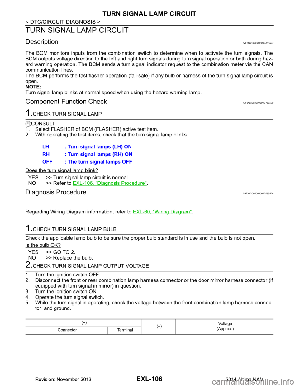
1.CHECK TURN SIGNAL LAMP
CONSULT
1. Select FLASHER of BCM (FLASHER) active test item.
2. With operating the test items, check that the turn signal lamp blinks.
Does the turn signal lamp blink?
YES >> Turn signal lamp circuit is normal.
NO >> Refer to EXL-106, "Diagnosis Procedure"
.
Diagnosis ProcedureINFOID:0000000009463599
Regarding Wiring Diagram information, refer to EXL-60, "Wiring Diagram".
1.CHECK TURN SIGNAL LAMP BULB
Check the applicable lamp bulb to be sure the proper bulb standard is in use and the bulb is not open.
Is the bulb OK?
YES >> GO TO 2.
NO >> Replace the bulb.
2.CHECK TURN SIGNAL LAMP OUTPUT VOLTAGE
1. Turn the ignition switch OFF.
2. Disconnect the front or rear combination lamp har ness connector or the door mirror harness connector (if
equipped with turn signal in mirror) in question.
3. Turn the ignition switch ON.
4. Operate the turn signal switch.
5. While the turn signal is operating, check the vo ltage between the front combination lamp harness connec-
tor and ground. LH : Turn signal lamps (LH) ON
RH : Turn signal lamps (RH) ON
OFF : The turn signal lamps OFF
(+) (− ) Vo l ta g e
(Approx.)
Connector Terminal
Revision: November 20132014 Altima NAMRevision: November 20132014 Altima NAM
Page 2376 of 4801
EXL-110
< DTC/CIRCUIT DIAGNOSIS >
OPTICAL SENSOR
OPTICAL SENSOR
DescriptionINFOID:0000000009463600
The optical sensor measures ambient light and transmits the optical sensor signal to the BCM.
Component Function CheckINFOID:0000000009463601
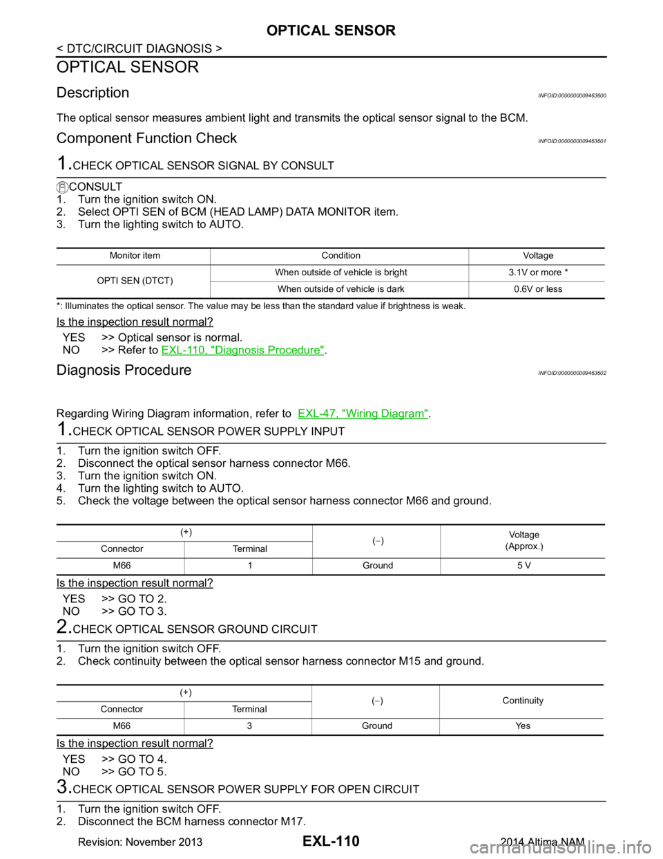
1.CHECK OPTICAL SENSOR SIGNAL BY CONSULT
CONSULT
1. Turn the ignition switch ON.
2. Select OPTI SEN of BCM (HEAD LAMP) DATA MONITOR item.
3. Turn the lighting switch to AUTO.
*: Illuminates the optical sensor. The value may be less than the standard value if brightness is weak.
Is the inspection result normal?
YES >> Optical sensor is normal.
NO >> Refer to EXL-110, "Diagnosis Procedure"
.
Diagnosis ProcedureINFOID:0000000009463602
Regarding Wiring Diagram information, refer to EXL-47, "Wiring Diagram".
1.CHECK OPTICAL SENSOR POWER SUPPLY INPUT
1. Turn the ignition switch OFF.
2. Disconnect the optical sensor harness connector M66.
3. Turn the ignition switch ON.
4. Turn the lighting switch to AUTO.
5. Check the voltage between the optical sensor harness connector M66 and ground.
Is the inspection result normal?
YES >> GO TO 2.
NO >> GO TO 3.
2.CHECK OPTICAL SENSOR GROUND CIRCUIT
1. Turn the ignition switch OFF.
2. Check continuity between the optical sensor harness connector M15 and ground.
Is the inspection result normal?
YES >> GO TO 4.
NO >> GO TO 5.
3.CHECK OPTICAL SENSOR POWER SUPPLY FOR OPEN CIRCUIT
1. Turn the ignition switch OFF.
2. Disconnect the BCM harness connector M17.
Monitor item Condition Voltage
OPTI SEN (DTCT) When outside of vehicle is bright 3.1V or more *
When outside of vehicle is dark 0.6V or less
(+) (− ) Vo l ta g e
(Approx.)
Connector Terminal
M66 1 Ground 5 V
(+) (− )Continuity
Connector Terminal
M66 3 Ground Yes
Revision: November 20132014 Altima NAMRevision: November 20132014 Altima NAM
Page 2378 of 4801
EXL-112
< DTC/CIRCUIT DIAGNOSIS >
HAZARD SWITCH
HAZARD SWITCH
Component Function CheckINFOID:0000000009463603
1.CHECK HAZARD SWITCH SIGNAL BY CONSULT
CONSULT DATA MONITOR
1. Turn ignition switch ON.
2. Select HAZARD SW of BCM (F LASHER) Data Monitor item.
3. While operating the hazard switch, check the monitor status.
Is the inspection result normal?
YES >> Hazard switch circuit is normal.
NO >> Refer to EXL-112, "Diagnosis Procedure"
.
Diagnosis ProcedureINFOID:0000000009463604
Regarding Wiring Diagram information, refer to EXL-60, "Wiring Diagram".
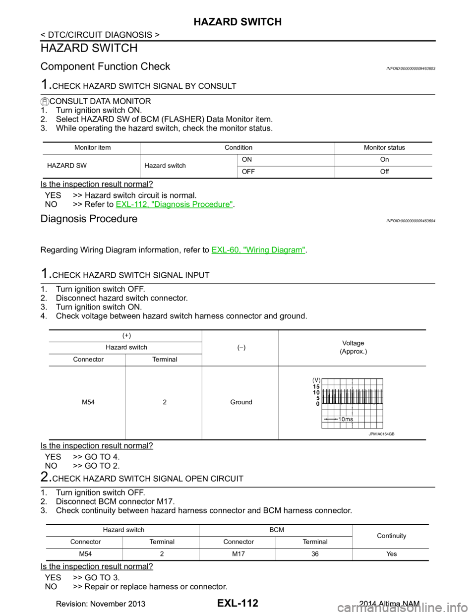
1.CHECK HAZARD SWITCH SIGNAL INPUT
1. Turn ignition switch OFF.
2. Disconnect hazard switch connector.
3. Turn ignition switch ON.
4. Check voltage between hazard s witch harness connector and ground.
Is the inspection result normal?
YES >> GO TO 4.
NO >> GO TO 2.
2.CHECK HAZARD SWITCH SIGNAL OPEN CIRCUIT
1. Turn ignition switch OFF.
2. Disconnect BCM connector M17.
3. Check continuity between hazard har ness connector and BCM harness connector.
Is the inspection result normal?
YES >> GO TO 3.
NO >> Repair or replace harness or connector.
Monitor item Condition Monitor status
HAZARD SW Hazard switch ON On
OFF Off
(+) (− ) Vol tag e
(Approx.)
Hazard switch
Connector Terminal
M54 2 Ground
JPMIA0154GB
Hazard switch BCM Continuity
Connector Terminal Connector Terminal
M54 2 M17 36 Yes
Revision: November 20132014 Altima NAMRevision: November 20132014 Altima NAM
Page 2529 of 4801

GI-1
GENERAL INFORMATION
C
D E
F
G H
I
J
K L
M B
GI
SECTION GI
N
O P
CONTENTS
GENERAL INFORMATION
HOW TO USE THIS MANU AL ......................3
HOW TO USE THIS MANUAL ....................... .....3
Description .......................................................... ......3
Terms ........................................................................3
Units ..........................................................................3
Contents ....................................................................3
Relation between Illustrations and Descriptions .......4
Components ..............................................................4
HOW TO FOLLOW TROUBLE DIAGNOSES .....6
Description ................................................................6
How to Follow Test Groups in Trouble Diagnosis ......6
Key to Symbols Signifying Measurements or Pro-
cedures ............................................................... ......
7
HOW TO READ WIRING DIAGRAMS ................9
Connector symbols ............................................. ......9
Sample/wiring diagram -example- ...........................10
Description ..............................................................11
ABBREVIATIONS .......................................... ....13
Abbreviation List .................................................. ....13
TIGHTENING TORQUE OF STANDARD
BOLTS ............................................................ ....
18
Description .......................................................... ....18
Tightening Torque Table (New Standard Includ-
ed) ....................................................................... ....
18
RECOMMENDED CHEMICAL PRODUCTS
AND SEALANTS ............................................ ....
21
Recommended Chemical Products and Sealants ....21
VEHICLE INFORMATION ............................22
IDENTIFICATION INFORMATION ................. ....22
Model Variation ................................................... ....22
Identification Number ..............................................23
Identification Plate ...................................................24
Engine Serial Number .............................................24
CVT Number ...........................................................25
Dimensions .......................................................... ....25
Wheels & Tires ........................................................25
PRECAUTION ..............................................26
PRECAUTIONS .................................................26
Description ........................................................... ....26
Precaution for Supplemental Restraint System
(SRS) "AIR BAG" and "SEAT BELT PRE-TEN-
SIONER" ............................................................. ....
26
Precautions For Xenon Headlamp Service .............26
Procedures without Cowl Top Cover .......................27
Cautions in Removing Battery Terminal and AV
Control Unit .......................................................... ....
27
General Precautions ................................................27
Three Way Catalyst .................................................29
Fuel (Regular Unleaded Gasoline Recommend-
ed) QR25DE ........................................................ ....
29
Fuel (Regular Unleaded Gasoline Recommend-
ed) VQ35DE ........................................................ ....
29
Multiport Fuel Injection System or Engine Control
System ................................................................. ....
29
Hoses ......................................................................29
Engine Oils ..............................................................30
Air Conditioning .......................................................31
LIFTING POINT .................................................32
Special Service Tool ................................................32
Pantograph Jack ......................................................32
Garage Jack and Safety Stand ................................33
2-Pole Lift ................................................................34
Board-on Lift ............................................................35
TOW TRUCK TOWING .....................................36
Tow Truck Towing ...................................................36
Vehicle Recovery (Freeing a Stuck Vehicle) ...........36
WIRING DIAGRAM ......................................38
CONSULT CHECKING SYSTEM .....................38
Wiring Diagram .................................................... ....38
Revision: November 20132014 Altima NAMRevision: November 20132014 Altima NAM
Page 2534 of 4801
GI-6
< HOW TO USE THIS MANUAL >
HOW TO FOLLOW TROUBLE DIAGNOSES
HOW TO FOLLOW TROUBLE DIAGNOSES
DescriptionINFOID:0000000009462973
NOTICE:
Trouble diagnoses indicate work procedures required to diagnose problems effectively. Observe the following
instructions before diagnosing.
• Before performing trouble diagnoses, read the “Work Flow” in each section.
• After repairs, re-check that the problem has been completely eliminated.
• Refer to Component Parts and Harness Connector Locat ion for the Systems described in each section for
identification/location of components and harness connectors.
• When checking circuit continuity, ignition switch should be OFF.
• Refer to the Circuit Diagram for quick pinpoint check.
If you need to check circuit continui ty between harness connectors in more detail, such as when a sub-har-
ness is used, refer to Wiring Diagram in each individual section and Harness Layout in PG section for identi-
fication of harness connectors.
• Before checking voltage at connectors, check battery voltage.
• After accomplishing the Diagnosis Procedures and Elec trical Components Inspection, make sure that all
harness connectors are reconnected as they were.
How to Follow Test Grou ps in Trouble DiagnosisINFOID:0000000009462974
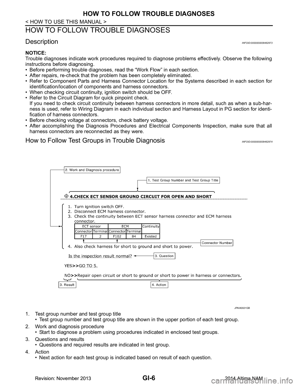
1. Test group number and test group title
• Test group number and test group title are s hown in the upper portion of each test group.
2. Work and diagnosis procedure • Start to diagnose a problem using procedur es indicated in enclosed test groups.
3. Questions and results • Questions and required results are indicated in test group.
4. Action • Next action for each test group is indicated based on result of each question.
JPAIA0021GB
Revision: November 20132014 Altima NAMRevision: November 20132014 Altima NAM
Page 2537 of 4801
HOW TO READ WIRING DIAGRAMSGI-9
< HOW TO USE THIS MANUAL >
C
D E
F
G H
I
J
K L
M B
GI
N
O PHOW TO READ WIRING DIAGRAMS
Connector symbolsINFOID:0000000009462976
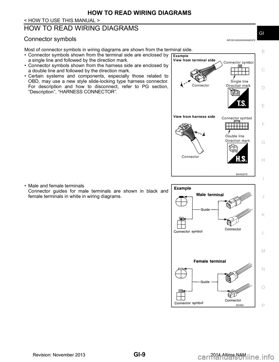
Most of connector symbols in wiring diagrams are shown from the terminal side.
• Connector symbols shown from the terminal side are enclosed by a single line and followed by the direction mark.
• Connector symbols shown from the harness side are enclosed by
a double line and followed by the direction mark.
• Certain systems and components, especially those related to
OBD, may use a new style slide-locking type harness connector.
For description and how to disconnect, refer to PG section,
“Description”, “HARNESS CONNECTOR”.
• Male and female terminals Connector guides for male terminals are shown in black and
female terminals in white in wiring diagrams.
SAIA0257E
SGI363
Revision: November 20132014 Altima NAMRevision: November 20132014 Altima NAM