Page 1989 of 4801
![NISSAN TEANA 2014 Service Manual
ENGINE CONTROL SYSTEM SYMPTOMSEC-989
< SYMPTOM DIAGNOSIS > [VQ35DE]
C
D E
F
G H
I
J
K L
M A
EC
NP
O
SYMPTOM
Reference
page
HARD/NO START/RESTART (EXCP. HA)
ENGINE STALL
HESITATION/SURGING/FLAT SP](/manual-img/5/57390/w960_57390-1988.png "NISSAN TEANA 2014 Service Manual
ENGINE CONTROL SYSTEM SYMPTOMSEC-989
< SYMPTOM DIAGNOSIS > [VQ35DE]
C
D E
F
G H
I
J
K L
M A
EC
NP
O
SYMPTOM
Reference
page
HARD/NO START/RESTART (EXCP. HA)
ENGINE STALL
HESITATION/SURGING/FLAT SP")
ENGINE CONTROL SYSTEM SYMPTOMSEC-989
< SYMPTOM DIAGNOSIS > [VQ35DE]
C
D E
F
G H
I
J
K L
M A
EC
NP
O
SYMPTOM
Reference
page
HARD/NO START/RESTART (EXCP. HA)
ENGINE STALL
HESITATION/SURGING/FLAT SPOT
SPARK KNOCK/DETONATION
LACK OF POWER/POOR ACCELERATION
HIGH IDLE/LOW IDLE
ROUGH IDLE/HUNTING
IDLING VIBRATION
SLOW/NO RETURN TO IDLE
OVERHEATS/WATER TEMPERATURE HIGH
EXCESSIVE FUEL CONSUMPTION
EXCESSIVE OIL CONSUMPTION
BATTERY DEAD (UNDER CHARGE)
Warranty symptom code AA AB AC AD AE AF AG AH AJ AK AL AM HA
Fuel Fuel tank 5
5 FL-5
Fuel piping 5 5 5 5 5 5
Va p o r l o c k —
Valve deposit 5 555 55 5 —
Poor fuel (Heavy weight gasoline,
Low octane) —
Air Air duct
55555 5 EM-144
Air cleaner
EM-137
Air leakage from air duct
(Mass air flow sensor — electric
throttle control actuator) 5555 EM-144
Electric throttle control actuator
EM-146
Air leakage from intake manifold/
Collector/Gasket EM-146,
EM-149
Cranking Battery
111111
11
PG-4
Generator circuit
CHG-17,
CHG-20
Starter circuit 3 STR-12,
STR-16
Signal plate 6 EM-224
PNP signal 4TM-299
Engine Cylinder head
55555 55 5 EM-207
Cylinder head gasket 4 3
Cylinder block
66666 66 6 4
EM-224
Piston
Piston ring
Connecting rod
Bearing
Crankshaft
Revision: November 20132014 Altima NAMRevision: November 20132014 Altima NAM
Page 1990 of 4801
![NISSAN TEANA 2014 Service Manual
EC-990
< SYMPTOM DIAGNOSIS >[VQ35DE]
ENGINE CONTROL SYSTEM SYMPTOMS
1 - 6: The numbers refer to the order of inspection.Va l v e
mecha-
nism Timing chain
55555 55 5 EM-182
Camshaft
EM-194
Intake](/manual-img/5/57390/w960_57390-1989.png "NISSAN TEANA 2014 Service Manual
EC-990
< SYMPTOM DIAGNOSIS >[VQ35DE]
ENGINE CONTROL SYSTEM SYMPTOMS
1 - 6: The numbers refer to the order of inspection.Va l v e
mecha-
nism Timing chain
55555 55 5 EM-182
Camshaft
EM-194
Intake")
EC-990
< SYMPTOM DIAGNOSIS >[VQ35DE]
ENGINE CONTROL SYSTEM SYMPTOMS
1 - 6: The numbers refer to the order of inspection.Va l v e
mecha-
nism Timing chain
55555 55 5 EM-182
Camshaft
EM-194
Intake valve timing controlEM-172,
EM-173
Intake valve 3EM-210
Exhaust valve
Exhaust Exhaust manifold/Tube/Muffler/ Gasket 55555 55 5 EM-152
,
EM-153
,
EX-11
Three way catalyst
Lubrica-
tion Oil pan/Oil strainer/Oil pump/Oil
filter/Oil gallery/Oil cooler 55555 55 5 EM-156
,
LU-27
, LU-
29, LU-32
Oil level (Low)/Filthy oil LU-25
Cooling
Radiator/Hose/Radiator filler cap
55555 55 45 CO-40,
CO-51
Thermostat 5 CO-49
Water pumpCO-44
Water galleryCO-31
Cooling fan
5CO-42
Coolant level (Low)/Contaminat-
ed coolant CO-35
NVIS (NISSAN Vehicle Immobilizer System —
NATS) 11
SEC-11
SYMPTOM
Reference
page
HARD/NO START/RESTART (EXCP. HA)
ENGINE STALL
HESITATION/SURGING/FLAT SPOT
SPARK KNOCK/DETONATION
LACK OF POWER/POOR ACCELERATION
HIGH IDLE/LOW IDLE
ROUGH IDLE/HUNTING
IDLING VIBRATION
SLOW/NO RETURN TO IDLE
OVERHEATS/WATER TEMPERATURE HIGH
EXCESSIVE FUEL CONSUMPTION
EXCESSIVE OIL CONSUMPTION
BATTERY DEAD (UNDER CHARGE)
Warranty symptom code AA AB AC AD AE AF AG AH AJ AK AL AM HA
Revision: November 20132014 Altima NAMRevision: November 20132014 Altima NAM
Page 4160 of 4801

SYSTEMSTC-9
< SYSTEM DESCRIPTION >
C
D E
F
H I
J
K L
M A
B
STC
N
O P
HYDRAULIC PUMP ELECTRIC POWER STEE RING SYSTEM : Protection Function
INFOID:0000000009460346
• When the steering wheel is operated repeatedly or turned all the way for a long period during parking or low
speed driving, the function of the hydraulic pump elec tric power steering system becomes limited to prevent
the system from overheating. Cont inued operation of the steering wheel will cause the hydraulic pump elec-
tric power steering system to stop and the hydraulic pum p electric power steering system warning lamp may
come ON. In this case, the steering wheel operation temporarily becomes hard. This is not a malfunction.
When the engine is turned OFF (ignition switch OFF) and steering operation is stopped for a while, the tem-
perature of the hydraulic pump electric power steer ing system decreases and the steering operation returns
to normal after restarting the engine.
• Then, the hydraulic pump electric power steering syste m warning lamp turns OFF. If the system is OFF
under the protection state, the hydraulic pump electr ic power steering system warning lamp turns ON to
warn that the system is in the manual steering state. (This is not a system malfunction.) In addition, the fol-
lowing DTC remains to distinguish from malfunction.
C1608 Manual steering state
U1000 Normal control
NOTE:
If the cause is in a different ECU, the state changes to fixed steering assist force.
DTC Fail-safe condition
DTC vehicle condition
C160A The system temporarily enters the manual steering state. (This is not a hydraulic pump electric
power steering system malfunction.)
Revision: November 20132014 Altima NAMRevision: November 20132014 Altima NAM
Page 4163 of 4801
STC-12
< ECU DIAGNOSIS INFORMATION >
POWER STEERING CONTROL MODULE
*4: This may not agree with the speedometer indication immediately after the ignition switch is turned ON. This
is not a malfunction.
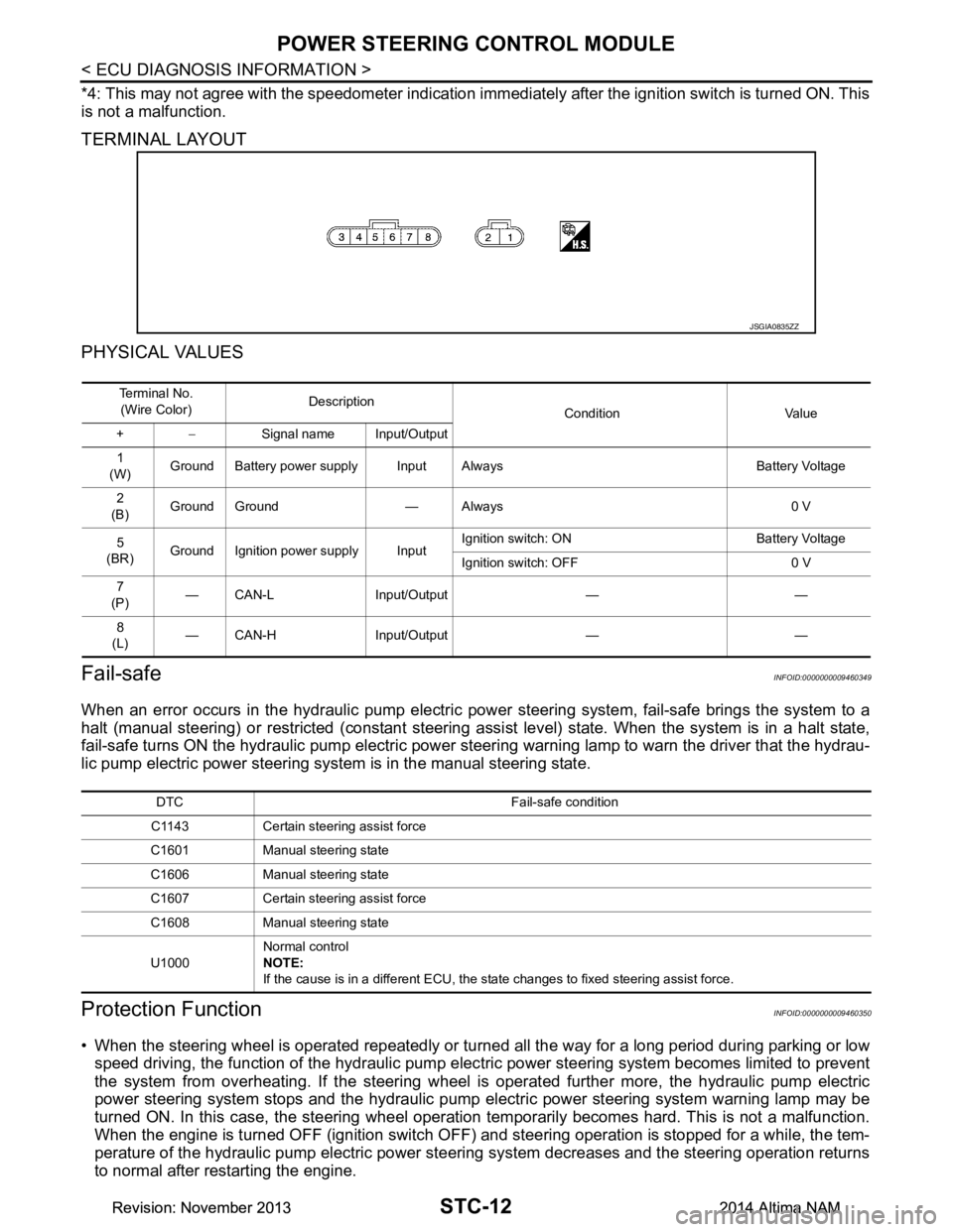
TERMINAL LAYOUT
PHYSICAL VALUES
Fail-safeINFOID:0000000009460349
When an error occurs in the hydraulic pump electric pow er steering system, fail-safe brings the system to a
halt (manual steering) or restricted (constant steering assi st level) state. When the system is in a halt state,
fail-safe turns ON the hydraulic pump electric power steer ing warning lamp to warn the driver that the hydrau-
lic pump electric power steering system is in the manual steering state.
Protection FunctionINFOID:0000000009460350
• When the steering wheel is operated repeatedly or turned all the way for a long period during parking or low
speed driving, the function of the hydraulic pump elec tric power steering system becomes limited to prevent
the system from overheating. If the steering wheel is operated further more, the hydraulic pump electric
power steering system stops and the hydraulic pump el ectric power steering system warning lamp may be
turned ON. In this case, the steering wheel operation temporarily becomes hard. This is not a malfunction.
When the engine is turned OFF (ignition switch OFF) and steering operation is stopped for a while, the tem-
perature of the hydraulic pump electric power steeri ng system decreases and the steering operation returns
to normal after restarting the engine.
JSGIA0835ZZ
Te r m i n a l N o .
(Wire Color) Description
Condition Value
+ − Signal name Input/Output
1
(W) Ground Battery power supply Input Always Battery Voltage
2
(B) Ground Ground — Always 0 V
5
(BR) Ground Ignition power supply Input Ignition switch: ON Battery Voltage
Ignition switch: OFF 0 V
7
(P) — CAN-L Input/Output — —
8
(L) — CAN-H Input/Output — —
DTC Fail-safe condition
C1143 Certain steering assist force
C1601 Manual steering state
C1606 Manual steering state
C1607 Certain steering assist force
C1608 Manual steering state
U1000 Normal control
NOTE:
If the cause is in a different ECU, the state changes to fixed steering assist force.
Revision: November 20132014 Altima NAMRevision: November 20132014 Altima NAM