2014 NISSAN TEANA engine coolant
[x] Cancel search: engine coolantPage 3267 of 4801

MWI-12
< SYSTEM DESCRIPTION >
SYSTEM
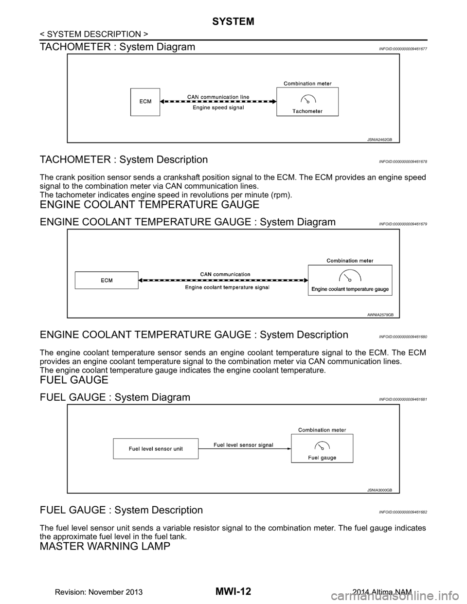
TACHOMETER : System Diagram
INFOID:0000000009461677
TACHOMETER : System DescriptionINFOID:0000000009461678
The crank position sensor sends a crankshaft positi on signal to the ECM. The ECM provides an engine speed
signal to the combination meter via CAN communication lines.
The tachometer indicates engine speed in revolutions per minute (rpm).
ENGINE COOLANT TEMPERATURE GAUGE
ENGINE COOLANT TEMPERATURE GAUGE : System DiagramINFOID:0000000009461679
ENGINE COOLANT TEMPERATURE GAUGE : System DescriptionINFOID:0000000009461680
The engine coolant temperature sensor sends an engine coolant temperature signal to the ECM. The ECM
provides an engine coolant temperature signal to t he combination meter via CAN communication lines.
The engine coolant temperature gauge indicates the engine coolant temperature.
FUEL GAUGE
FUEL GAUGE : System DiagramINFOID:0000000009461681
FUEL GAUGE : System DescriptionINFOID:0000000009461682
The fuel level sensor unit sends a variable resistor signal to the combination meter. The fuel gauge indicates
the approximate fuel level in the fuel tank.
MASTER WARNING LAMP
JSNIA2462GB
AWNIA2579GB
JSNIA3000GB
Revision: November 20132014 Altima NAMRevision: November 20132014 Altima NAM
Page 3269 of 4801

MWI-14
< SYSTEM DESCRIPTION >
SYSTEM
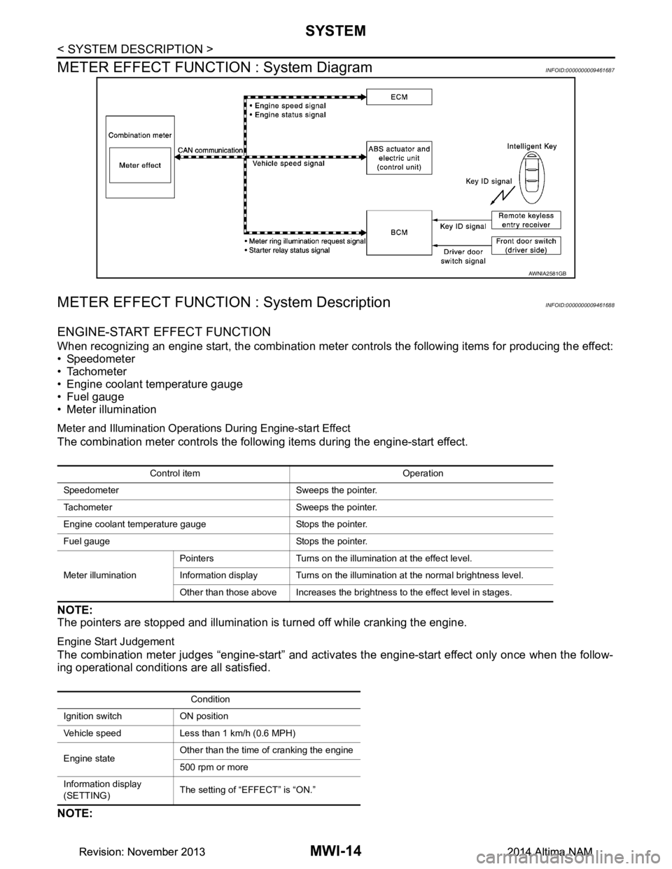
METER EFFECT FUNCTION : System Diagram
INFOID:0000000009461687
METER EFFECT FUNCTION : System DescriptionINFOID:0000000009461688
ENGINE-START EFFECT FUNCTION
When recognizing an engine start, the combination meter c ontrols the following items for producing the effect:
• Speedometer
• Tachometer
• Engine coolant temperature gauge
• Fuel gauge
• Meter illumination
Meter and Illumination Operations During Engine-start Effect
The combination meter controls the following items during the engine-start effect.
NOTE:
The pointers are stopped and illumination is turned off while cranking the engine.
Engine Start Judgement
The combination meter judges “engine-start” and activates the engine-start effect only once when the follow-
ing operational conditions are all satisfied.
NOTE:
AWNIA2581GB
Control item Operation
Speedometer Sweeps the pointer.
Tachometer Sweeps the pointer.
Engine coolant temperature gauge Stops the pointer.
Fuel gauge Stops the pointer.
Meter illumination Pointers Turns on the illumination at the effect level.
Information display Turns on the illumination at the normal brightness level.
Other than those above Increases the brightness to the effect level in stages.
Condition
Ignition switch ON position
Vehicle speed Less than 1 km/h (0.6 MPH)
Engine state Other than the time of cranking the engine
500 rpm or more
Information display
(SETTING) The setting of “EFFECT” is “ON.”
Revision: November 20132014 Altima NAMRevision: November 20132014 Altima NAM
Page 3274 of 4801
![NISSAN TEANA 2014 Service Manual
MWI
DIAGNOSIS SYSTEM (METER)MWI-19
< SYSTEM DESCRIPTION >
C
D E
F
G H
I
J
K L
M B
A
O P
Refer to MWI-27, "DTC Index".
DATA MONITOR
Display Item List
X: Applicable
Display item [Unit] MAIN
SIGNALS NISSAN TEANA 2014 Service Manual
MWI
DIAGNOSIS SYSTEM (METER)MWI-19
< SYSTEM DESCRIPTION >
C
D E
F
G H
I
J
K L
M B
A
O P
Refer to MWI-27, "DTC Index".
DATA MONITOR
Display Item List
X: Applicable
Display item [Unit] MAIN
SIGNALS](/manual-img/5/57390/w960_57390-3273.png)
MWI
DIAGNOSIS SYSTEM (METER)MWI-19
< SYSTEM DESCRIPTION >
C
D E
F
G H
I
J
K L
M B
A
O P
Refer to MWI-27, "DTC Index".
DATA MONITOR
Display Item List
X: Applicable
Display item [Unit] MAIN
SIGNALS Description
SPEED METER
[mph or km/h] X Displays the value of vehicle speed signal.
SPEED OUTPUT
[mph or km/h] X Vehicle speed signal value transmitted to other units via CAN communication.
ODO OUTPUT
[mph or km/h] Odometer signal value transmitted to other units via CAN communication.
TACHO METER
[rpm] X Value of the engine speed signal received from ECM via CAN communication.
FUEL METER
[L] X Fuel level indicated on combination meter.
W TEMP METER
[ ° F] or [ °C] X Displays the value of engine coolant temperature signal, which is input from ECM.
ABS W/L
[On/Off] Displays [ON/OFF] condition of ABS warning indicator.
VDC/TCS IND
[ON/OFF] Displays [ON/OFF] condition of VDC OFF indicator lamp.
SLIP IND
[ON/OFF] Displays [ON/OFF] condition of SLIP indicator lamp.
BRAKE W/L
[ON/OFF] Displays [ON/OFF] condition of brake warning indicator.
DOOR W/L
[ON/OFF] Displays [ON/OFF] condition of door warning message.
TRUNK/GLAS-H
[On/Off] Displays [ON/OFF] condition of trunk warning message.
HI-BEAM IND
[ON/OFF] Displays [ON/OFF] condition of high beam indicator.
TURN IND
[On/Off] Displays [ON/OFF] condition of turn indicator.
FR FOG IND
[On/Off] Displays [ON/OFF] condition of front fog lamp indicator.
LIGHT IND
[On/Off] Displays [ON/OFF] condition of light indicator.
OIL W/L
[ON/OFF] Displays [ON/OFF] condition of low oil pressure warning message.
MIL
[ON/OFF] Displays [ON/OFF] condition of malfunction indicator.
CRUISE IND
[Off] Displays [ON/OFF] condition of CRUISE
indicator in the information display.
CRUISE W/L
[ON/OFF] Displays [ON/OFF] condition of
tire CRUISE warning message.
CVT IND
[Off] Displays [ON/OFF] condition of CVT indicator in the information display.
SET IND
[On/Off] Displays [ON/OFF] condition of SET indicator in the information display.
O/D OFF IND
[ON/OFF] Displays [ON/OFF] condition of O/D OFF indicator.
Revision: November 20132014 Altima NAMRevision: November 20132014 Altima NAM
Page 3277 of 4801

MWI-22
< ECU DIAGNOSIS INFORMATION >
COMBINATION METER
ECU DIAGNOSIS INFORMATION
COMBINATION METER
Reference ValueINFOID:0000000009461694
VALUES ON THE DIAGNOSIS TOOL
Monitor Item Condition Value/Status
SPEED METER
[mph or km/h] Ignition switch ON While driving
Input value of vehicle speed signal
(CAN communication signal)
SPEED OUTPUT
[mph or km/h] Ignition switch ON While driving Output value of vehicle speed sig-
nal (CAN communication signal)
ODO OUTPUT
[mph or km/h] Ignition switch ON — Output value of odometer signal
(CAN communication signal)
TACHO METER
[rpm] Ignition switch ON Engine running
Input value of engine speed signal
(CAN communication signal)
FUEL METER
[L] Ignition switch ON — Input value of fuel level sensor sig-
nal
W TEMP METER
[ ° F] or [ °C] Ignition switch ON — Input value of engine coolant tem-
perature signal (CAN communica-
tion signal)
ABS W/L Ignition switch ON ABS warning lamp ON On
ABS warning lamp OFF Off
VDC/TCS IND Ignition switch ON VDC OFF indica
tor lamp ON On
VDC OFF indicato r lamp OFF Off
SLIP IND Ignition switch ON VDC warning lamp ON On
VDC warning lamp OFF Off
BRAKE W/L Ignition switch ON Brake warning lamp ON On
Brake warning lamp OFF Off
DOOR W/L Ignition switch ON Door open warning ON On
Other than the above Off
TRUNK/GLAS-H Ignition switch ON Trunk open warning ON On
Trunk open warning OFF Off
HI-BEAM IND Ignition switch ON High beam indicator lamp ON On
High beam indicator lamp OFF Off
TURN IND Ignition switch ON Turn signal indicator lamp ON On
Turn signal indicator lamp OFF Off
LIGHT IND Ignition switch ON Tail lamp indicator lamp ON On
Tail lamp indicator lamp OFF Off
FR FOG IND Ignition switch ON Front fog lamp indicator lamp ON On
Front fog lamp indicator lamp OFF Off
OIL W/L Ignition switch ON Oil pressure warning On
Oil pressure warning Off
MIL Ignition switch ON Malfunction indicator lamp ON On
Malfunction indicator lamp OFF Off
CRUISE IND Ignition switch ON CRUISE indicator ON On
CRUISE indicator OFF Off
Revision: November 20132014 Altima NAMRevision: November 20132014 Altima NAM
Page 3282 of 4801

MWI
COMBINATION METERMWI-27
< ECU DIAGNOSIS INFORMATION >
C
D E
F
G H
I
J
K L
M B
A
O PFail-SafeINFOID:0000000009461695
FA I L - S A F E
The combination meter activates the fail-safe contro l if CAN communication with each unit is malfunctioning.
DTC IndexINFOID:0000000009461696
52
(P) Ground O/D OFF/SPORT switch Input Ignition
switch
ON O/D OFF switch pressed 0 V
Other than the above 5 V
Te r m i n a l N o .
(Wire color) Description
ConditionVa l u e
(Approx.)
+ – Signal name Input/
Output
Function Specifications
Speedometer Reset to zero by suspending communication.
Tachometer
Engine coolant temperature gauge
Illumination control When suspending communication, changes to nighttime mode.
Information display Odo/trip meter An indicated value is maintained at communications blackout.
Shift position indicator The display turns OFF by suspending communication.
Warning messages The display turns OFF by suspending communication.
Buzzer The buzzer turns OFF by suspending communication.
Warning lamp/indicator lamp ABS warning lamp
The lamp turns ON by suspending communication.
O/D OFF indicator lamp
Slip indicator lamp
Brake warning lamp
Malfunction indicator lamp
VDC OFF indicator lamp
EPS warning lamp
Low tire pressure warning lamp The lamp blinking caused by suspending communication.
High beam indicator lamp
The lamp turns OFF by suspending communication.
Turn signal indicator lamp
Master warning lamp
Front lamp indicator lamp
Lane departure warning
Tail lamp indicator lamp
Air bag warning lamp
The lamp turns off when disconnected.
Charge warning lamp
Seat belt warning lamp
Security indicator lamp
Display contents of CONSULT Diagnostic item is detected when... Refer to
CAN COMM CIRCUIT
[U1000] When combination meter is not transmitting or receiving CAN communication signal for 2
seconds or more. MWI-53
CONTROL UNIT (CAN)
[U1010] When detecting error during the initial diagnosis of the CAN controller of combination
meter. MWI-54
Revision: November 20132014 Altima NAMRevision: November 20132014 Altima NAM
Page 3283 of 4801
![NISSAN TEANA 2014 Service Manual
MWI-28
< ECU DIAGNOSIS INFORMATION >
COMBINATION METER
VEHICLE SPEED CIRC
[B2205] The abnormal vehicl
e speed signal is input from the ABS actuator and electric unit (control
unit) for 2 seconds NISSAN TEANA 2014 Service Manual
MWI-28
< ECU DIAGNOSIS INFORMATION >
COMBINATION METER
VEHICLE SPEED CIRC
[B2205] The abnormal vehicl
e speed signal is input from the ABS actuator and electric unit (control
unit) for 2 seconds](/manual-img/5/57390/w960_57390-3282.png)
MWI-28
< ECU DIAGNOSIS INFORMATION >
COMBINATION METER
VEHICLE SPEED CIRC
[B2205] The abnormal vehicl
e speed signal is input from the ABS actuator and electric unit (control
unit) for 2 seconds or more. MWI-55
TACHO METER
[B2267] If ECM continuously transmits abnormal engine speed signals for 2 seconds or more.
MWI-56
WATER TEMP METER
[B2268] If ECM continuously transmits abnormal engine coolant temperature signals for 60 sec-
onds or more. MWI-57
Display contents of CONSULT Diagnostic item is detected when... Refer to
Revision: November 20132014 Altima NAMRevision: November 20132014 Altima NAM
Page 3312 of 4801

MWI
B2268 WATER TEMPMWI-57
< DTC/CIRCUIT DIAGNOSIS >
C
D E
F
G H
I
J
K L
M B
A
O P
B2268 WATER TEMP
DescriptionINFOID:0000000009461712
The engine coolant temperature signal is transmitted fr om ECM to the combination meter via CAN communi-
cation.
DTC LogicINFOID:0000000009461713
DTC DETECTION LOGIC
Diagnosis ProcedureINFOID:0000000009461714
1.PERFORM SELF-DIAGNOSIS OF ECM
Perform Self Diagnostic Result of ECM, and repair or replace malfunctioning parts.
>> Refer to (QR25DE) EC-77, "CONSULT Function"
or (VQ35DE) EC-601, "CONSULT Function".
DTC CONSULT Detection condition Probable malfunction location
B2268 WATER TEMP METER ECM continuously transmits abnormal engine coolant
temperature signals for 60 seconds or more • Engine coolant temperature sensor
•ECM
Revision: November 20132014 Altima NAMRevision: November 20132014 Altima NAM
Page 3481 of 4801

PG
HARNESSPG-49
< DTC/CIRCUIT DIAGNOSIS >
C
D E
F
G H
I
J
K L
B
A
O P
N
B5 F6 — : Generator C2 F45 GR/2 : Knock sensor
B4 F7 B/3 : Generator F4 F46 GR/22 : CVT unit
F2 F8 B/3 : Primary speed sensor F5 F47 B/6 : Joint connector-F01
B3 F9 — : Engine ground E5 F48 B/10 : Joint connector-F02
F 3 F 1 0 B / 1 : IPDM E/R (Intelligent power distribution
module engine room) E5 F49 B/10 : Joint connector-F03
F 5 F 1 3 B R / 4 8 : E C M ( Q R 2 5 D E e x c e p t f o r C a l i f o r n i a ) A 2 F 5 1 G / 2 : Intake valve timing intermediate lock
control solenoid valve
E5 F14 B/48 : ECM (QR25DE except for California) B2 F52 B/3 : Intake manifold runner control valve
position sensor
B3 F15 — : Engine ground G4 F53 W/4 : Joint connector-F07
E5 F16 B/48 : TCM (Transmission control module) E3 F54 GR/2 : Engine coolant temperature sensor (With
QR25DE)
B2 F17 GR/2 : Fuel injector no. 1 D3 F55 B/3 : Camshaft position sensor (PHASE)
B2 F18 GR/2 : Fuel injector no. 2 D2 F57 B/6 : Electric throttle control actuator
C 2 F 1 9 G R / 2 : F u e l i n j e c t o r n o . 3 D 3 F 5 8 B / 3 : Exhaust valve timing control position
sensor
D 2 F 2 0 G R / 2 : F u e l i n j e c t o r n o . 4 A 2 F 5 9 G / 2 : Intake valve timing control solenoid
valve
E1 F23 B/3 : Output speed sensor B2 F68 GR/2 : Engine oil temperature sensor
D4 F24 GR/4 : Air fuel ratio (A/F) sensor 1 G4 F70 W/4 : Joint connector-F08
G 4 F 2 5 B R / 8 : To E 2 3 A 3 F 8 0 G / 2 : Exhaust valve timing control solenoid
valve
E 3 F 2 6 W / 2 : C o n d e n s e r G 3 F 8 3 W / 1 0 : IPDM E/R (Intelligent power distribution
module engine room)
E 4 F 2 7 — : S t a r t e r m o t o r G 3 F 8 4 W / 1 2 : IPDM E/R (Intelligent power distribution
module engine room)
E4 F28 — : Starter motor (With QR25DE) E3 F85 B/10 : Transmission range switch
C 1 F 2 9 L / 2 : EVAP canister purge volume control
solenoid valve (With QR25DE) E3 F86 B/3 : Input speed sensor
D2 F30 B/3 : Crankshaft position sensor (POS) A2 F87 B/3 : Engine oil pressure sensor
E2 F31 GR/6 : Mass air flow sensor (With QR25DE) A4 F88 GR/2 : A/C compressor
B 3 F 3 4 G R / 3 : Ignition coil no. 1 (With power
transistor) A1 F89 B/3 : Manifold absolute pressure (Map) sensor
C 3 F 3 5 G R / 3 : Ignition coil no. 2 (With power
transistor) F5 F90 BR/48 : ECM (QR25DE for California)
C 3 F 3 6 G R / 3 : Ignition coil no. 3 (With power
transistor) F5 F91 B/48 : ECM (QR25DE for California)
Revision: November 20132014 Altima NAM