2014 NISSAN TEANA maintenance
[x] Cancel search: maintenancePage 4632 of 4801
VTL-4
< PERIODIC MAINTENANCE >
IN-CABIN MICROFILTER
PERIODIC MAINTENANCE
IN-CABIN MICROFILTER
Removal and InstallationINFOID:0000000009461574
REMOVAL
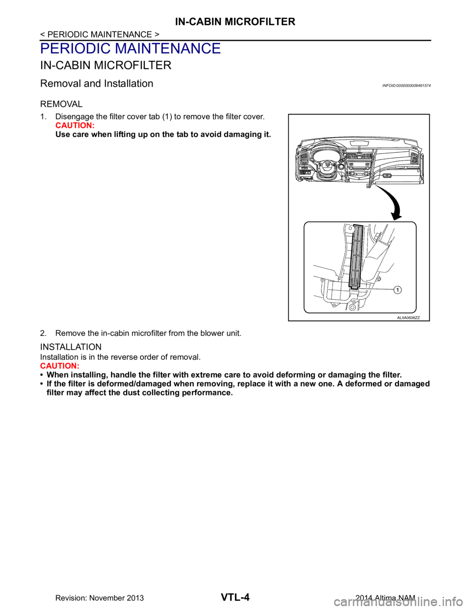
1. Disengage the filter cover tab (1) to remove the filter cover.CAUTION:
Use care when lifting up on th e tab to avoid damaging it.
2. Remove the in-cabin microfilter from the blower unit.
INSTALLATION
Installation is in the reverse order of removal.
CAUTION:
• When installing, handle the filter with extreme care to avoid deforming or damaging the filter.
• If the filter is deformed/damaged when removing , replace it with a new one. A deformed or damaged
filter may affect the du st collecting performance.
ALIIA0636ZZ
Revision: November 20132014 Altima NAM
Page 4645 of 4801
WCS
PRECAUTIONSWCS-3
< PRECAUTION >
C
D E
F
G H
I
J
K L
M B
A
O P
PRECAUTION
PRECAUTIONS
Precaution for Supplemental Restraint System (SRS) "AIR BAG" and "SEAT BELT
PRE-TENSIONER"
INFOID:0000000009955588
The Supplemental Restraint System such as “A IR BAG” and “SEAT BELT PRE-TENSIONER”, used along
with a front seat belt, helps to reduce the risk or severi ty of injury to the driver and front passenger for certain
types of collision. Information necessary to service t he system safely is included in the SR and SB section of
this Service Manual.
WARNING:
• To avoid rendering the SRS inoper ative, which could increase the risk of personal injury or death in
the event of a collision which would result in air bag inflation, all maintenance must be performed by
an authorized NISSAN/INFINITI dealer.
• Improper maintenance, including in correct removal and installation of the SRS, can lead to personal
injury caused by unintentional act ivation of the system. For removal of Spiral Cable and Air Bag
Module, see the SR section.
• Do not use electrical test equipm ent on any circuit related to the SRS unless instructed to in this
Service Manual. SRS wiring harnesses can be identi fied by yellow and/or orange harnesses or har-
ness connectors.
PRECAUTIONS WHEN USING POWER TOOLS (AIR OR ELECTRIC) AND HAMMERS
WARNING:
• When working near the Airbag Diagnosis Sensor Un it or other Airbag System sensors with the Igni-
tion ON or engine running, DO NOT use air or el ectric power tools or strike near the sensor(s) with a
hammer. Heavy vibration could activate the sensor( s) and deploy the air bag(s), possibly causing
serious injury.
• When using air or electric power tools or hammers , always switch the Ignition OFF, disconnect the
battery and wait at least three mi nutes before performing any service.
Revision: November 20132014 Altima NAMRevision: November 20132014 Altima NAM
Page 4677 of 4801

WT-2
C1720, C1721, C1722, C1723 TRANSMITTER ...
37
DTC Logic ............................................................ ...37
Diagnosis Procedure ..............................................37
C1724, C1725, C1726, C1727 TRANSMITTER
(BATT VOLT) .................................................. ...
39
DTC Logic ............................................................ ...39
Diagnosis Procedure ..............................................39
C1729 VEHICLE SPEED SIGNAL ....................41
DTC Logic ............................................................ ...41
Diagnosis Procedure ..............................................41
C1730, C1731, C1732, C1733 FLAT TIRE ........42
DTC Logic ............................................................ ...42
Diagnosis Procedure ..............................................42
C1734 BCM ........................................................44
DTC Logic ............................................................ ...44
Diagnosis Procedure ..............................................44
C1735 IGNITION SIGNAL .................................46
DTC Logic ............................................................ ...46
Diagnosis Procedure ..............................................46
SYMPTOM DIAGNOSIS .............................48
TPMS .............................................................. ...48
Symptom Table ................................................... ...48
LOW TIRE PRESSURE WARNING LAMP
DOES NOT TURN ON .................................... ...
49
Low Tire Pressure Warning Lamp Does Not Come
On When Ignition Switch Is Turned On ............... ...
49
LOW TIRE PRESSURE WARNING LAMP
STAYS ON ...................................................... ...
50
Low Tire Pressure Warning Lamp Stays On When
Ignition Switch Is Turned On ................................ ...
50
EASY FILL TIRE ALERT DOES NOT ACTI-
VATE ............................................................... ...
51
Description ........................................................... ...51
Diagnosis Procedure ...............................................51
NOISE, VIBRATION AND HARSHNESS
(NVH) TROUBLESHOOTING ......................... ...
52
NVH Troubleshooting Chart ....................................52
PERIODIC MAINTENANCE .......................53
ROAD WHEEL ................................................ ...53
Inspection ............................................................. ...53
REMOVAL AND INSTALLATION ..............54
REMOTE KEYLESS ENTRY RECEIVER ...... ...54
Removal and Installation .........................................54
ROAD WHEEL TIRE ASSEMBLY ................. ...55
Adjustment ........................................................... ...55
UNIT REMOVAL AND INSTALLATION ....57
TIRE PRESSURE SENSOR ........................... ...57
Exploded View ..................................................... ...57
Removal and Installation .........................................57
SERVICE DATA AND SPECIFICATIONS
(SDS) ............... ...........................................
60
SERVICE DATA AND SPECIFICATIONS
(SDS) .............................................................. ...
60
Road Wheel ......................................................... ...60
Tire ..........................................................................60
Revision: November 20132014 Altima NAMRevision: November 20132014 Altima NAM
Page 4678 of 4801
PRECAUTIONSWT-3
< PRECAUTION >
C
D
F
G H
I
J
K L
M A
B
WT
N
O P
PRECAUTION
PRECAUTIONS
Precaution for Supplemental Restraint System (SRS) "AIR BAG" and "SEAT BELT
PRE-TENSIONER"
INFOID:0000000009951708
The Supplemental Restraint System such as “A IR BAG” and “SEAT BELT PRE-TENSIONER”, used along
with a front seat belt, helps to reduce the risk or severi ty of injury to the driver and front passenger for certain
types of collision. Information necessary to service t he system safely is included in the SR and SB section of
this Service Manual.
WARNING:
• To avoid rendering the SRS inoper ative, which could increase the risk of personal injury or death in
the event of a collision which would result in air bag inflation, all maintenance must be performed by
an authorized NISSAN/INFINITI dealer.
• Improper maintenance, including in correct removal and installation of the SRS, can lead to personal
injury caused by unintentional act ivation of the system. For removal of Spiral Cable and Air Bag
Module, see the SR section.
• Do not use electrical test equipm ent on any circuit related to the SRS unless instructed to in this
Service Manual. SRS wiring harnesses can be identi fied by yellow and/or orange harnesses or har-
ness connectors.
PRECAUTIONS WHEN USING POWER TOOLS (AIR OR ELECTRIC) AND HAMMERS
WARNING:
• When working near the Airbag Diagnosis Sensor Un it or other Airbag System sensors with the Igni-
tion ON or engine running, DO NOT use air or el ectric power tools or strike near the sensor(s) with a
hammer. Heavy vibration could activate the sensor( s) and deploy the air bag(s), possibly causing
serious injury.
• When using air or electric power tools or hammers , always switch the Ignition OFF, disconnect the
battery and wait at least three mi nutes before performing any service.
Service Notice and Precautions for TPMSINFOID:0000000009464472
WARNING:
Radio waves could adversely affect electrical medi cal equipment. Those who use a pacemaker should
contact the electrical medical equipment manu facturer for possible influences before use.
• Low tire pressure warning lamp blinks for 1 minute, then turns ON when any malfunction occurs except low
tire pressure. Erase the self-diagnosis memories for Tire Pressure Monitoring System (TPMS), or register
the ID to turn low tire pressure warning lamp OFF. For ID registration, refer to WT-25, "Work Procedure"
.
• ID registration is required when replacing or rotating wheels, replacing tire pressure sensor or BCM. Refer to WT-25, "Work Procedure"
.
• For easy fill tire alert function, refer to the following. WT-9, "Easy Fill Tire Alert Function"
- When inflating the tires, park the vehicle in the safe area and ensure the safety of the working area.
- Read and understand the easy fill tire alert function prior to use.
- Inflate the tires one at a time.
- If there is no response for approximately 15 seconds or mo re after inflating the tires, cancel the use of the
easy fill tire alert function or move the vehicle approximately 1 m (3.2 ft) backward or forward to try again.
The air filler pressure may be weak or out of service area.
- Despite the high-precision TPMS pressure sensor, an i ndicated value may differ from that of the pressure
gauge.
- Air pressure is measured rather high due to the rise in tire air temperature after driving.
- If TPMS is malfunctioning, the easy fill tire alert is unusable.
• Replace grommet seal, valve core and valve cap of tire pressure sensor in TPMS when replacing each tire
by reaching the wear limit. Refer to WT-57, "Exploded View"
.
• Because the tire pressure sensor conforms to No rth America radio law, the following items must be
observed.
- The sensor may be used only in North America.
- It may not be used in any method other than the specified method.
- It must not be disassembled or modified.
Revision: November 20132014 Altima NAMRevision: November 20132014 Altima NAM
Page 4728 of 4801
ROAD WHEELWT-53
< PERIODIC MAINTENANCE >
C
D
F
G H
I
J
K L
M A
B
WT
N
O P
PERIODIC MAINTENANCE
ROAD WHEEL
InspectionINFOID:0000000009464520
ALUMINUM WHEEL
1. Check tires for wear and improper inflation.
2. Check wheels for deformation, cracks and other damage. If deformed, remove wheel and check wheel
runout.
3. Remove tire from aluminum wheel and mount wheel on a tire balance machine.
CAUTION:
DO NOT use center hole cone-type clamping machines to
hold the wheel assembly during tire removal/installation or
balancing. Damage to the wheel finish, cladding or chrome
may occur. Use only rim-type or universal lug-type clamp-
ing machines to hold the wheel assembly.
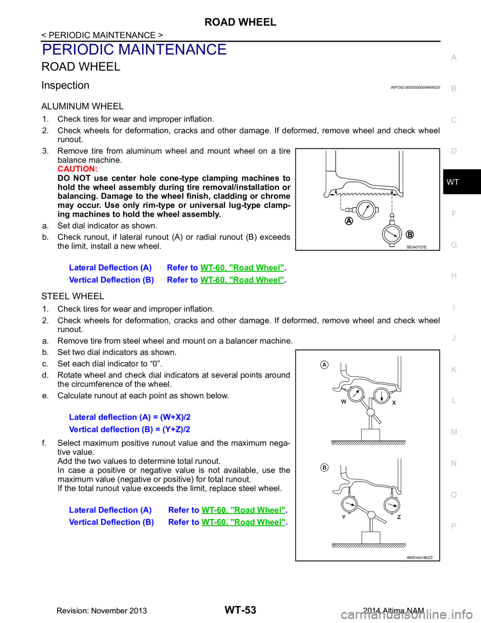
a. Set dial indicator as shown.
b. Check runout, if lateral runout (A) or radial runout (B) exceeds
the limit, install a new wheel.
STEEL WHEEL
1. Check tires for wear and improper inflation.
2. Check wheels for deformation, cracks and other damage. If deformed, remove wheel and check wheel
runout.
a. Remove tire from steel wheel and mount on a balancer machine.
b. Set two dial indicators as shown.
c. Set each dial indicator to “0”.
d. Rotate wheel and check dial indicators at several points around the circumference of the wheel.
e. Calculate runout at each point as shown below.
f. Select maximum positive runout value and the maximum nega- tive value.
Add the two values to determine total runout.
In case a positive or negative value is not available, use the
maximum value (negative or positive) for total runout.
If the total runout value exceeds the limit, replace steel wheel.
Lateral Deflection (A) Refer to
WT-60, "Road Wheel"
.
Vertical Deflection (B) Refer to WT-60, "Road Wheel"
.
SEIA0737E
Lateral deflection (A) = (W+X)/2
Vertical deflection (B) = (Y+Z)/2
Lateral Deflection (A) Refer to WT-60, "Road Wheel"
.
Vertical Deflection (B) Refer to WT-60, "Road Wheel"
.
AWEIA0186ZZ
Revision: November 20132014 Altima NAMRevision: November 20132014 Altima NAM
Page 4731 of 4801
WT-56
< REMOVAL AND INSTALLATION >
ROAD WHEEL TIRE ASSEMBLY
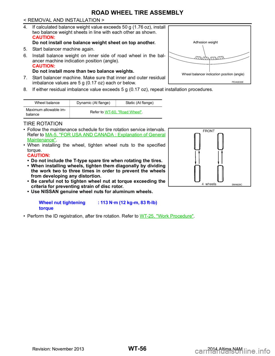
4. If calculated balance weight value exceeds 50 g (1.76 oz), installtwo balance weight sheets in line with each other as shown.
CAUTION:
Do not install one balance weight sheet on top another.
5. Start balancer machine again.
6. Install balance weight on inner side of road wheel in the bal- ancer machine indication position (angle).
CAUTION:
Do not install more than two balance weights.
7. Start balancer machine. Make sure that inner and outer residual imbalance values are 5 g (0.17 oz) each or below.
8. If either residual imbalance value exceeds 5 g (0.17 oz), repeat installation procedures.
TIRE ROTATION
• Follow the maintenance schedule for tire rotation service intervals.
Refer to MA-5, "FOR USA AND CANADA : Explanation of General
Maintenance".
• When installing the wheel, tighten wheel nuts to the specified torque.
CAUTION:
• Do not include the T-type spare tire when rotating the tires.
• When installing wheels, tighten them diagonally by dividing
the work two to three times in order to prevent the wheels
from developing any distortion.
• Be careful not to tighten wheel nut at torque exceeding the criteria for preventing strain of disc rotor.
• Use NISSAN genuine wheel nuts for aluminum wheels.
• Perform the ID registration, after tire rotation. Refer to WT-25, "Work Procedure"
.
Wheel balance Dynamic (At flange) Static (At flange)
Maximum allowable im-
balance Refer to
WT-60, "Road Wheel"
.
PEIA0033E
Wheel nut tightening
torque : 113 N·m (12 kg-m, 83 ft-lb)
SMA829C
Revision: November 20132014 Altima NAMRevision: November 20132014 Altima NAM
Page 4738 of 4801
PRECAUTIONSWW-3
< PRECAUTION >
C
D E
F
G H
I
J
K
M A
B
WW
N
O P
PRECAUTION
PRECAUTIONS
Precaution for Supplemental Restraint System (SRS) "AIR BAG" and "SEAT BELT
PRE-TENSIONER"
INFOID:0000000009951588
The Supplemental Restraint System such as “A IR BAG” and “SEAT BELT PRE-TENSIONER”, used along
with a front seat belt, helps to reduce the risk or severi ty of injury to the driver and front passenger for certain
types of collision. Information necessary to service t he system safely is included in the SR and SB section of
this Service Manual.
WARNING:
• To avoid rendering the SRS inoper ative, which could increase the risk of personal injury or death in
the event of a collision which would result in air bag inflation, all maintenance must be performed by
an authorized NISSAN/INFINITI dealer.
• Improper maintenance, including in correct removal and installation of the SRS, can lead to personal
injury caused by unintentional act ivation of the system. For removal of Spiral Cable and Air Bag
Module, see the SR section.
• Do not use electrical test equipm ent on any circuit related to the SRS unless instructed to in this
Service Manual. SRS wiring harnesses can be identi fied by yellow and/or orange harnesses or har-
ness connectors.
PRECAUTIONS WHEN USING POWER TOOLS (AIR OR ELECTRIC) AND HAMMERS
WARNING:
• When working near the Airbag Diagnosis Sensor Un it or other Airbag System sensors with the Igni-
tion ON or engine running, DO NOT use air or el ectric power tools or strike near the sensor(s) with a
hammer. Heavy vibration could activate the sensor( s) and deploy the air bag(s), possibly causing
serious injury.
• When using air or electric power tools or hammers , always switch the Ignition OFF, disconnect the
battery and wait at least three mi nutes before performing any service.
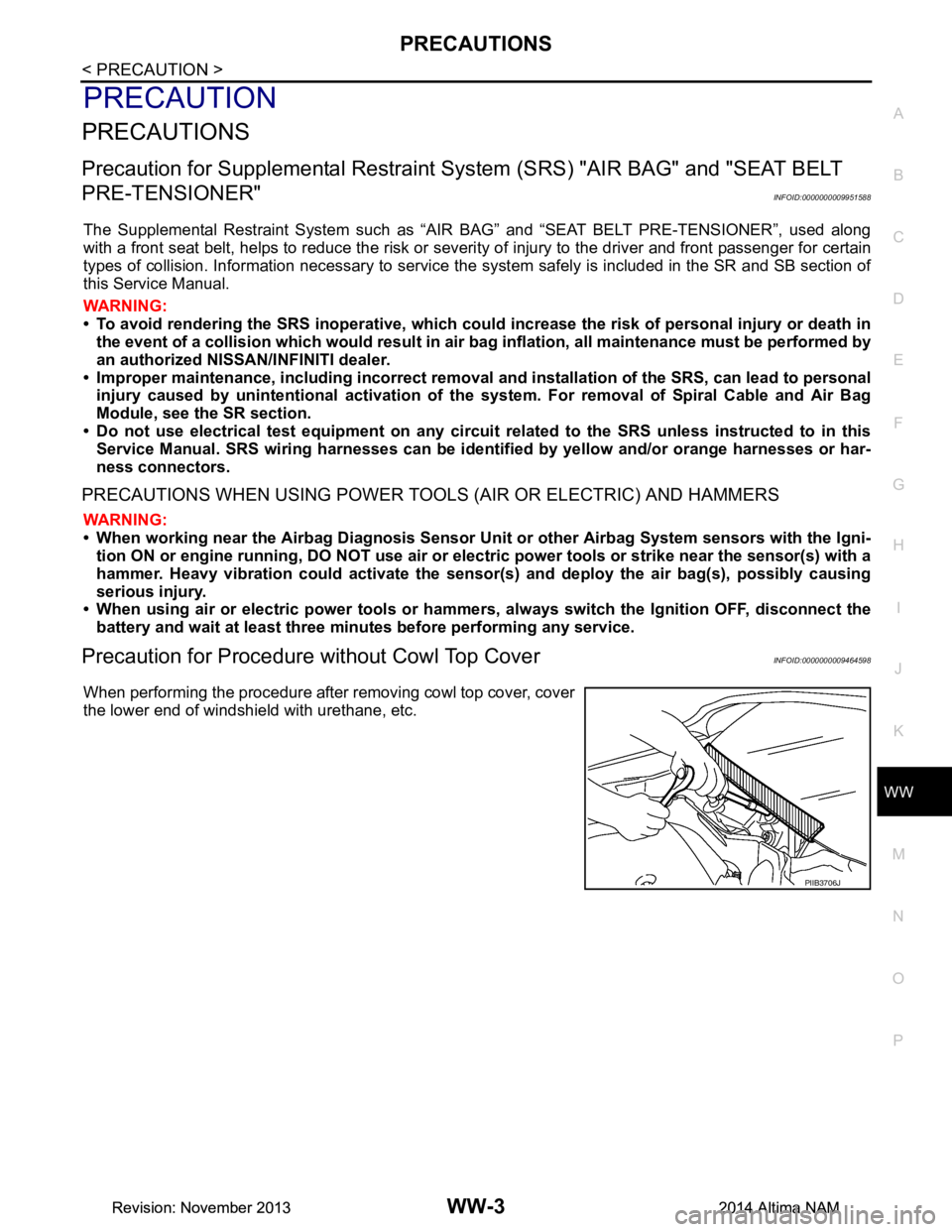
Precaution for Procedure without Cowl Top CoverINFOID:0000000009464598
When performing the procedure after removing cowl top cover, cover
the lower end of windshield with urethane, etc.
PIIB3706J
Revision: November 20132014 Altima NAMRevision: November 20132014 Altima NAM