2014 NISSAN TEANA transmission fluid
[x] Cancel search: transmission fluidPage 2221 of 4801
![NISSAN TEANA 2014 Service Manual
ENGINE ASSEMBLYEM-223
< UNIT REMOVAL AND INSTALLATION > [VQ35DE]
C
D E
F
G H
I
J
K L
M A
EM
NP
O
• Start engine. With engine speed increased, check again for fuel leakage at connection points.
� NISSAN TEANA 2014 Service Manual
ENGINE ASSEMBLYEM-223
< UNIT REMOVAL AND INSTALLATION > [VQ35DE]
C
D E
F
G H
I
J
K L
M A
EM
NP
O
• Start engine. With engine speed increased, check again for fuel leakage at connection points.
�](/manual-img/5/57390/w960_57390-2220.png)
ENGINE ASSEMBLYEM-223
< UNIT REMOVAL AND INSTALLATION > [VQ35DE]
C
D E
F
G H
I
J
K L
M A
EM
NP
O
• Start engine. With engine speed increased, check again for fuel leakage at connection points.
• Run engine to check for unusual noise and vibration. NOTE:
If hydraulic pressure inside timing chain tensioner dr ops after removal and installation, slack in the guide
may generate a pounding noise during and just after engine start. However, this is normal. Noise will stop
after hydraulic pressure rises.
• Warm up engine thoroughly to make sure there is no leak age of fuel, exhaust gas, or any oils/fluids including
engine oil and engine coolant.
• Bleed air from passages in lines and hoses, such as in cooling system.
• After cooling down engine, again check oil/fluid levels including engine oil and engine coolant. Refill to spec- ified level, if necessary.
• Summary of the inspection items:
*Power steering fluid, brake fluid, etc. Item Before starting engine Engine running After engine stopped
Engine coolant Level Leakage Level
Engine oil Level Leakage Level
Transmission/
transaxle fluid CVT Models Leakage Level/Leakage Leakage
Other oils and fluids* Level Leakage Level
Fuel Leakage Leakage Leakage
Exhaust gas — Leakage —
Revision: November 20132014 Altima NAM
Page 3193 of 4801
PERIODIC MAINTENANCEMA-9
< PERIODIC MAINTENANCE >
C
D E
F
G H
I
J
K L
M B
MA
N
O A
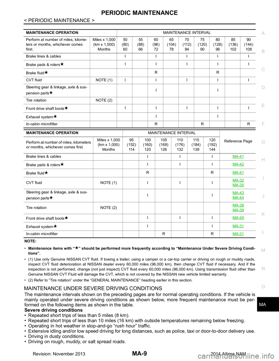
NOTE:
• Maintenance items with “ ” shoul d be performed more frequently according to “Maintenance Under Severe Driving Condi-
tions”.
• (1) Use only Genuine NISSAN CVT fluid. If towing a trailer, using a camper or a car-top carrier or driving on rough or muddy r oads,
inspect CVT fluid deteriorat ion at NISSAN dealer every 60,000 miles (96,000 km), then change CVT fluid if necessary. And if the
inspection is not performed, change (not just inspect) CVT fluid every 60,000 miles (96,000 km). Using transmission fluid other than
Genuine NISSAN CVT Fluid will damage the CVT, which is not covered by the NISSAN new vehicle limited warranty.
• (2) Refer to “Tire rotation” under the “GENERAL MAINTENANCE” heading earlier in this section.
MAINTENANCE UNDER SEVERE DRIVING CONDITIONS
The maintenance intervals shown on the preceding pages are for normal operating conditions. If the vehicle is
mainly operated under severe driving conditions as shown below, more frequent maintenance must be per-
formed on the following items as shown in the table.
Severe driving conditions
• Repeated short trips of less than 5 miles (8 km).
• Repeated short trips of less than 10 miles (16 km) wi th outside temperatures remaining below freezing.
• Operating in hot weather in stop-and-go “rush hour” traffic.
• Extensive idling and/or low speed driving for long distances , such as police, taxi or door-to-door delivery use.
• Driving in dusty conditions.
• Driving on rough, muddy, or salt spread roads.
MAINTENANCE OPERATION MAINTENANCE INTERVAL
Perform at number of miles, kilome-
ters or months, whichever comes
first. Miles x 1,000
(km x 1,000) Months 50
(80) 60 55
(88) 66 60
(96) 72 65
(104) 78 70
(112) 84 75
(120) 90 80
(128) 96 85
(136) 102 90
(144) 108
Brake lines & cables IIIII
Brake pads & roters IIIII
Brake fluid RR
CVT fluid NOTE (1)IIIII
Steering gear & linkage, axle & sus-
pension parts II
Tire rotation NOTE (2)
Front drive shaft boots IIIII
Exhaust system II
In-cabin microfilter R R R
MAINTENANCE OPERATION MAINTENANCE INTERVAL
Reference Page
Perform at number of miles, kilometers
or months, whichever comes first. Miles x 1,000
(km x 1,000)
Months 95
(152)
11 4 100
(160)
120 105
(168)
126 11 0
(176)
132 11 5
(184)
138 120
(192)
144
Brake lines & cables I I I MA-41
Brake pads & rotersIII
MA-42
Brake fluid RR
MA-41
CVT fluid NOTE (1)III MA-32MA-35
Steering gear & linkage, axle & sus-
pension parts II
MA-43
MA-44
Tire rotation NOTE (2) MA-38MA-39
Front drive shaft boots
III
MA-45
Exhaust system II
MA-31
In-cabin microfilter R R MA-31
Revision: November 20132014 Altima NAM
Page 3195 of 4801
RECOMMENDED FLUIDS AND LUBRICANTSMA-11
< PERIODIC MAINTENANCE >
C
D E
F
G H
I
J
K L
M B
MA
N
O A
RECOMMENDED FLUIDS AND LUBRICANTS
FOR USA AND CANADA
FOR USA AND CANADA :
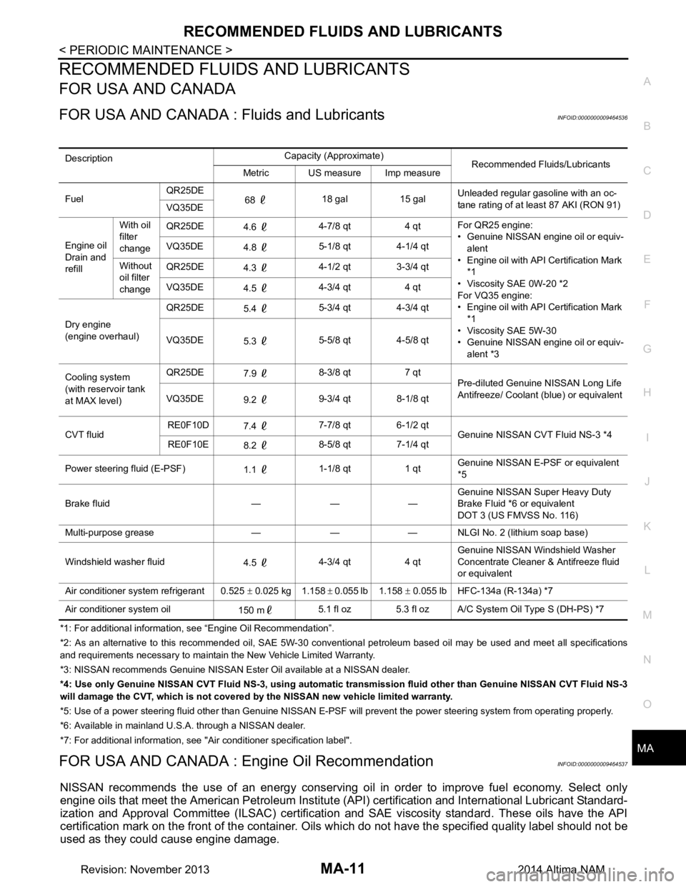
Fluids and LubricantsINFOID:0000000009464536
*1: For additional information, see “Engine Oil Recommendation”.
*2: As an alternative to this recommended oil, SAE 5W-30 conventional petroleum based oil may be used and meet all specificatio ns
and requirements necessary to maintain the New Vehicle Limited Warranty.
*3: NISSAN recommen ds Genuine NISSAN Ester Oil av ailable at a NISSAN dealer.
*4: Use only Genuine NISSAN CVT Fluid NS -3, using automatic transmission fluid other than Genuine NISSAN CVT Fluid NS-3
will damage the CVT, which is not covered by the NISSAN new vehicle limited warranty.
*5: Use of a power steering fluid other than Genuine NISSAN E-PSF will prevent the power steering system from operating properly.
*6: Available in mainland U. S.A. through a NISSAN dealer.
*7: For additional information, see "Air conditioner specification label".
FOR USA AND CANADA : En gine Oil RecommendationINFOID:0000000009464537
NISSAN recommends the use of an energy conserving o il in order to improve fuel economy. Select only
engine oils that meet the American Petroleum Institut e (API) certification and International Lubricant Standard-
ization and Approval Committee (ILSAC) certificati on and SAE viscosity standard. These oils have the API
certification mark on the front of the container. Oils which do not have the specified quality label should not be
used as they could cause engine damage.
Description Capacity (Approximate)
Recommended Fluids/Lubricants
Metric US measure Imp measure
Fuel QR25DE
68 18 gal 15 gal Unleaded regular gasoline with an oc-
tane rating of at least 87 AKI (RON 91)
VQ35DE
Engine oil
Drain and
refill With oil
filter
change QR25DE
4.6 4-7/8 qt 4 qt For QR25 engine:
• Genuine NISSAN engine oil or equiv- alent
• Engine oil with API Certification Mark
*1
• Viscosity SAE 0W-20 *2
For VQ35 engine:
• Engine oil with API Certification Mark
*1
• Viscosity SAE 5W-30
• Genuine NISSAN engine oil or equiv-
alent *3
VQ35DE
4.8 5-1/8 qt 4-1/4 qt
Without
oil filter
change QR25DE
4.3 4-1/2 qt 3-3/4 qt
VQ35DE 4.5 4-3/4 qt 4 qt
Dry engine
(engine overhaul) QR25DE
5.4 5-3/4 qt 4-3/4 qt
VQ35DE 5.3 5-5/8 qt 4-5/8 qt
Cooling system
(with reservoir tank
at MAX level) QR25DE
7.9 8-3/8 qt 7 qt
Pre-diluted Genuine NISSAN Long Life
Antifreeze/ Coolant (blue) or equivalent
VQ35DE 9.2 9-3/4 qt 8-1/8 qt
CVT fluid RE0F10D
7.4 7-7/8 qt 6-1/2 qt
Genuine NISSAN CVT Fluid NS-3 *4
RE0F10E 8.2 8-5/8 qt 7-1/4 qt
Power steering fluid (E-PSF) 1.1 1-1/8 qt 1 qt Genuine NISSAN E-PSF or equivalent
*5
Brake fluid — — — Genuine NISSAN Super Heavy Duty
Brake Fluid *6 or equivalent
DOT 3 (US FMVSS No. 116)
Multi-purpose grease — — — NLGI No. 2 (lithium soap base)
Windshield washer fluid 4.5 4-3/4 qt 4 qt Genuine NISSAN Windshield Washer
Concentrate Cleaner & Antifreeze fluid
or equivalent
Air conditioner system refrigerant 0.525 ± 0.025 kg 1.158 ± 0.055 lb 1.158 ± 0.055 lb HFC-134a (R-134a) *7
Air conditioner system oil 150 m5.1 fl oz 5.3 fl oz A/C System Oil Type S (DH-PS) *7
Revision: November 20132014 Altima NAM
Page 3199 of 4801
ENGINE MAINTENANCE (QR25DE)MA-15
< PERIODIC MAINTENANCE >
C
D E
F
G H
I
J
K L
M B
MA
N
O A
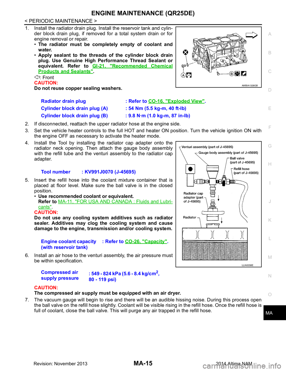
1. Install the radiator drain plug. Install the reservoir tank and cylin-
der block drain plug, if removed for a total system drain or for
engine removal or repair.
• The radiator must be completely empty of coolant and
water.
• Apply sealant to the threads of the cylinder block drain
plug. Use Genuine High Pe rformance Thread Sealant or
equivalent. Refer to GI-21, "Recommended Chemical
Products and Sealants".
: Front
CAUTION:
Do not reuse copper sealing washers.
2. If disconnected, reattach the upper radiator hose at the engine side.
3. Set the vehicle heater controls to the full HOT and heat er ON position. Turn the vehicle ignition ON with
the engine OFF as necessary to activate the heater mode.
4. Install the Tool by installing the radiator cap adapter onto the radiator neck opening. Then attach the gauge body assembly
with the refill tube and the venturi assembly to the radiator cap
adapter.
5. Insert the refill hose into the coolant mixture container that is
placed at floor level. Make sure the ball valve is in the closed
position.
• Use recommended coolant or equivalent.
Refer to MA-11, "FOR USA AND CANADA : Fluids and Lubri-
cants".
CAUTION:
Do not use any cooling system additives such as radiator
sealer. Additives may clog th e cooling system and cause
damage to the engine, transmission and/or cooling system.
6. Install an air hose to the venturi assembly, the air pressure must be within specification.
CAUTION:
The compressed air supply must be equipped with an air dryer.
7. The vacuum gauge will begin to rise and there will be an audible hissing noise. During this process open the ball valve on the refill hose slightly. Coolant will be vi sible rising in the refill hose. Once the refill hose is
full of coolant, close the ball valve. Th is will purge any air trapped in the refill hose.
Radiator drain plug : Refer to
CO-16, "Exploded View"
.
Cylinder block drain plug (A) : 54 Nm (5.5 kg-m, 40 ft-lb)
Cylinder block drain plug (B) : 9.8 N·m (1.0 kg-m, 87 in-lb)
Tool number : KV991J0070 (J-45695)
Engine coolant capacity
(with reservoir tank) : Refer to
CO-26, "Capacity"
.
Compressed air
supply pressure : 549 - 824 kPa (5.6 - 8.4 kg/cm
2,
80 - 119 psi)
AWBIA1328GB
LLIA0058E
Revision: November 20132014 Altima NAM
Page 3218 of 4801
MA-34
< PERIODIC MAINTENANCE >
CHASSIS AND BODY MAINTENANCE
34. Select “Data Monitor” in “TRANSMISSION” using CONSULT.
35. Select “CONFORM CVTF DETERIORTN”.
36. Select “Erase”.
37. Stop the engine.
CVT FLUID : AdjustmentINFOID:0000000009464569
CAUTION:
• During adjustment of the CVT fluid level, check CO NSULT so that the oil temperature may be main-
tained from 35 to 45 °C (95 to 113 °F).
• During adjustment of the CVT fluid level, check that the engine speed is maintaining 500 rpm.
• Use caution when looking into the drain hole as th ere is a risk of dripping fluid entering the eye.
1. Check that the selector lever is in the “P ” position, then completely engage the parking brake.
2. Start the engine.
3. Adjust the CVT fluid temperature to be approximately 40 °C (104 °F).
NOTE:
The CVT fluid is largely affected by temperature. Therefore be sure to use CONSULT and check the
“FLUID TEMP” under “TRANSMISSION” in “Data Monitor” while adjusting.
4. While depressing the brake pedal, shift the selector lever to the entire position from “P” to “DS”, and shift it to the “P” position.
NOTE:
Hold the lever at each position for 5 seconds.
5. Lift up the vehicle.
6. Check that there is no CVT fluid leakage.
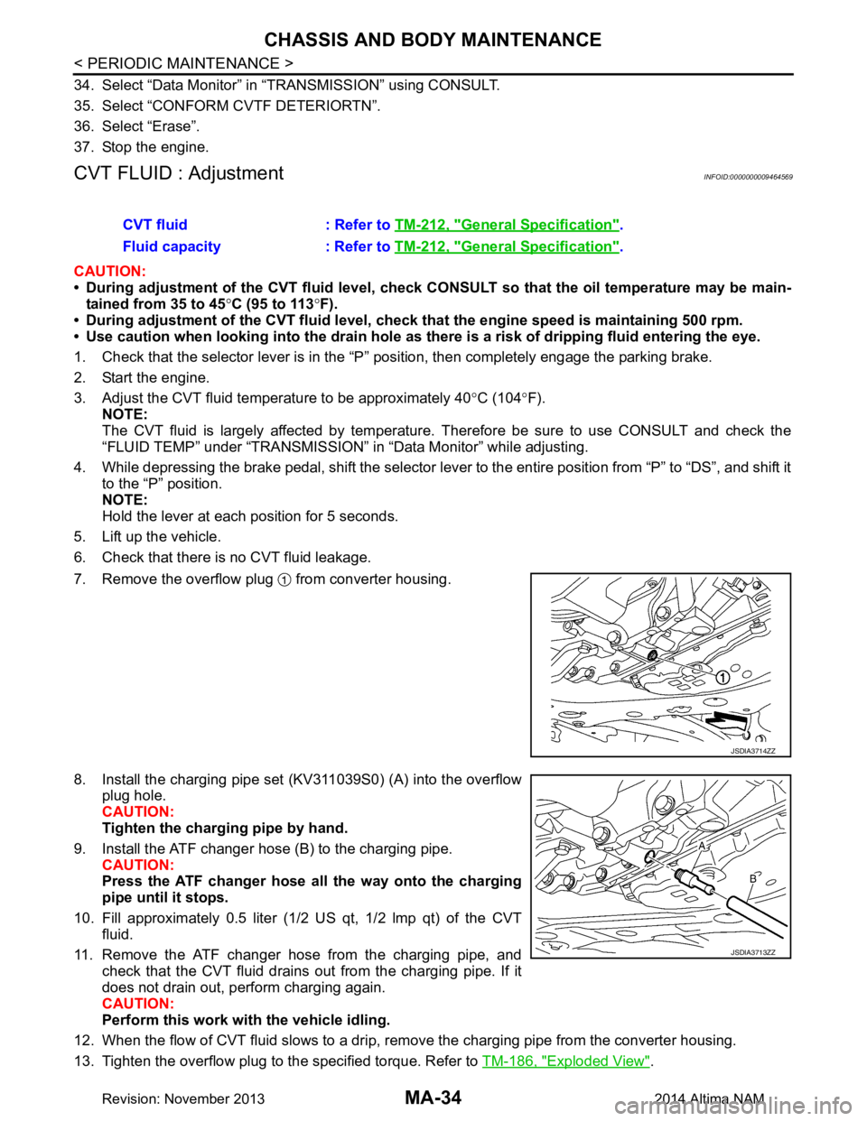
7. Remove the overflow plug from converter housing.
8. Install the charging pipe set (KV311039S0) (A) into the overflow plug hole.
CAUTION:
Tighten the charging pipe by hand.
9. Install the ATF changer hose (B) to the charging pipe. CAUTION:
Press the ATF changer hose all the way onto the charging
pipe until it stops.
10. Fill approximately 0.5 liter (1/2 US qt, 1/2 lmp qt) of the CVT
fluid.
11. Remove the ATF changer hose from the charging pipe, and check that the CVT fluid drains out from the charging pipe. If it
does not drain out, perform charging again.
CAUTION:
Perform this work with the vehicle idling.
12. When the flow of CVT fluid slows to a drip, re move the charging pipe from the converter housing.
13. Tighten the overflow plug to the specified torque. Refer to TM-186, "Exploded View"
.
CVT fluid : Refer to
TM-212, "General Specification"
.
Fluid capacity : Refer to TM-212, "General Specification"
.
JSDIA3714ZZ
JSDIA3713ZZ
Revision: November 20132014 Altima NAM
Page 3219 of 4801
CHASSIS AND BODY MAINTENANCEMA-35
< PERIODIC MAINTENANCE >
C
D E
F
G H
I
J
K L
M B
MA
N
O A
CAUTION:
Do not reuse O-ring.
14. Lift down the vehicle.
15. Stop the engine.
CVT FLUID : RE0F10EINFOID:0000000009464570
CVT FLUID : InspectionINFOID:0000000009464571
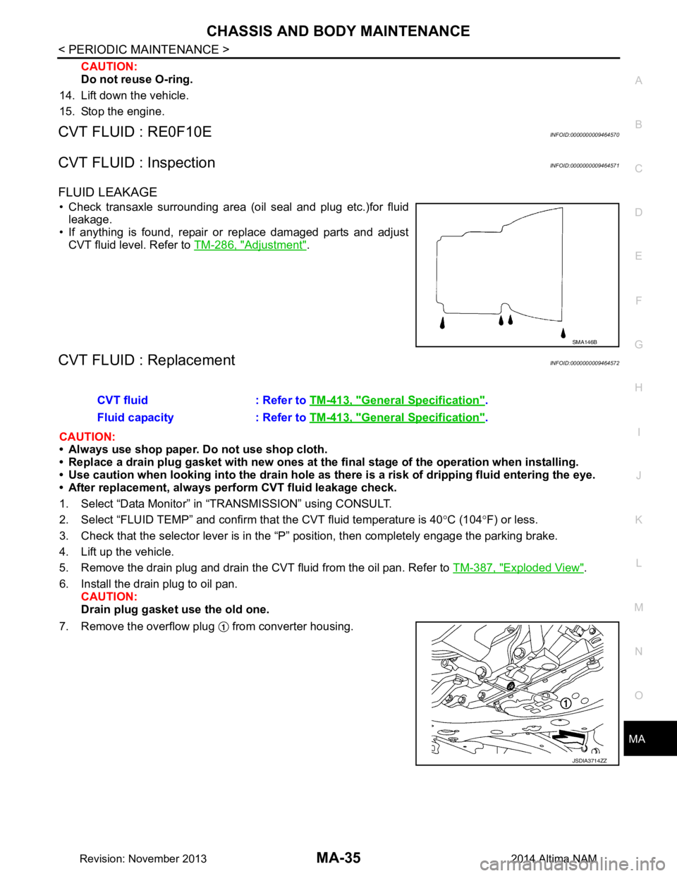
FLUID LEAKAGE
• Check transaxle surrounding area (oil seal and plug etc.)for fluid leakage.
• If anything is found, repair or replace damaged parts and adjust
CVT fluid level. Refer to TM-286, "Adjustment"
.
CVT FLUID : ReplacementINFOID:0000000009464572
CAUTION:
• Always use shop paper. Do not use shop cloth.
• Replace a drain plug gasket with new ones at the fi nal stage of the operation when installing.
• Use caution when looking into the drain hole as there is a risk of dripping fluid entering the eye.
• After replacement, always pe rform CVT fluid leakage check.
1. Select “Data Monitor” in “TRANSMISSION” using CONSULT.
2. Select “FLUID TEMP” and confirm t hat the CVT fluid temperature is 40°C (104 °F) or less.
3. Check that the selector lever is in the “P ” position, then completely engage the parking brake.
4. Lift up the vehicle.
5. Remove the drain plug and drain the CVT fluid from the oil pan. Refer to TM-387, "Exploded View"
.
6. Install the drain plug to oil pan. CAUTION:
Drain plug gasket use the old one.
7. Remove the overflow plug from converter housing.
SMA146B
CVT fluid : Refer to TM-413, "General Specification".
Fluid capacity : Refer to TM-413, "General Specification"
.
JSDIA3714ZZ
Revision: November 20132014 Altima NAM
Page 3221 of 4801
CHASSIS AND BODY MAINTENANCEMA-37
< PERIODIC MAINTENANCE >
C
D E
F
G H
I
J
K L
M B
MA
N
O A
34. Select “Data Monitor” in “TRANSMISSION” using CONSULT.
35. Select “CONFORM CVTF DETERIORTN”.
36. Select “Erase”.
37. Stop the engine.
CVT FLUID : AdjustmentINFOID:0000000009464573
CAUTION:
• During adjustment of the CVT fluid level, check CO NSULT so that the oil temperature may be main-
tained from 35 to 45 °C (95 to 113 °F).
• During adjustment of the CVT fluid level, check that the engine speed is maintaining 500 rpm.
• Use caution when looking into the drain hole as there is a risk of dripping fluid entering the eye.
1. Check that the selector lever is in the “P ” position, then completely engage the parking brake.
2. Start the engine.
3. Adjust the CVT fluid temperature to be approximately 40 °C (104 °F).
NOTE:
The CVT fluid is largely affected by temperature. Therefore be sure to use CONSULT and check the
“FLUID TEMP” under “TRA NSMISSION” in “Data Monitor” while adjusting.
4. While depressing the brake pedal, shift the selector leve r to the entire position from “P” to “DS”, and shift it
to the “P” position.
NOTE:
Hold the lever at each position for 5 seconds.
5. Lift up the vehicle.
6. Check that there is no CVT fluid leakage.
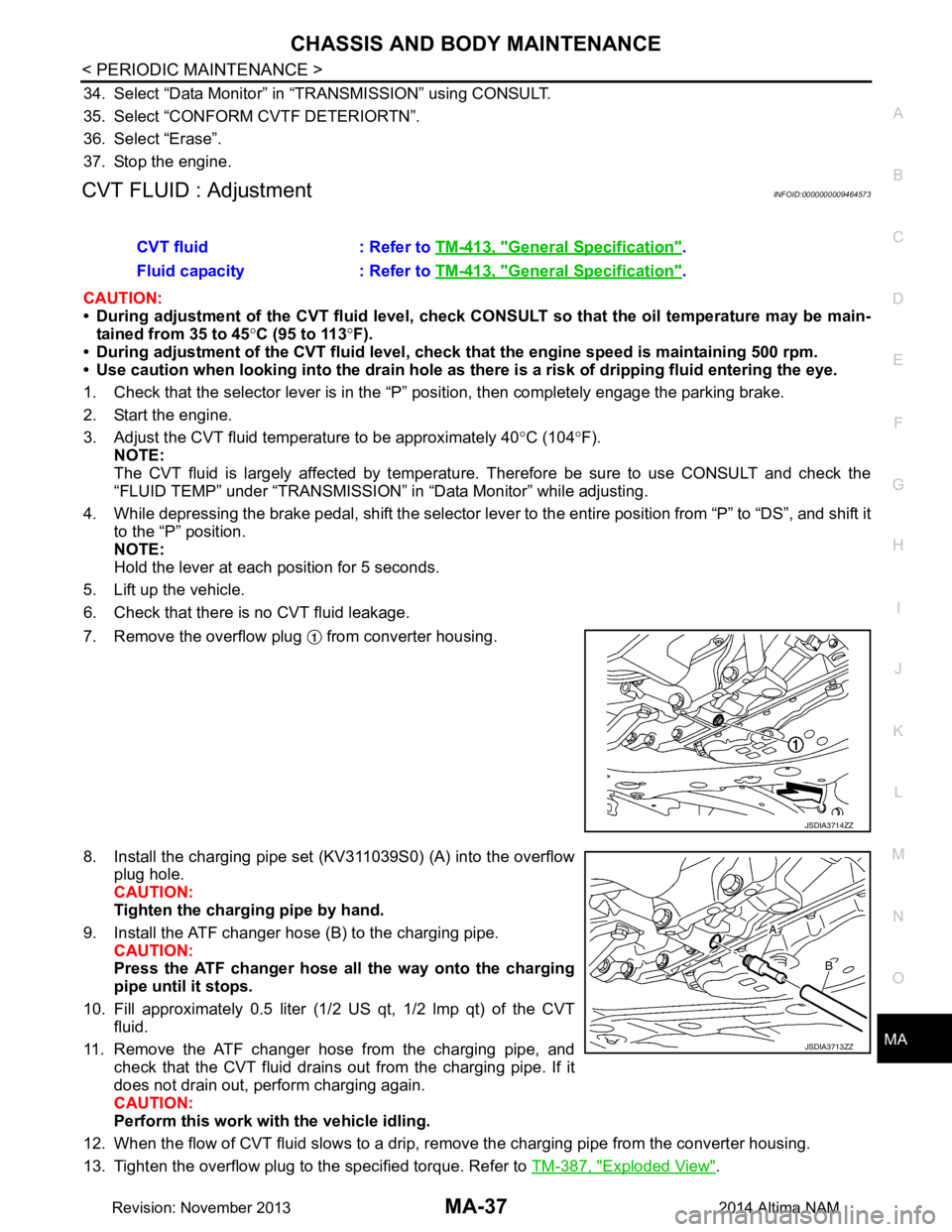
7. Remove the overflow plug from converter housing.
8. Install the charging pipe set (KV311039S0) (A) into the overflow plug hole.
CAUTION:
Tighten the charging pipe by hand.
9. Install the ATF changer hose (B) to the charging pipe. CAUTION:
Press the ATF changer hose all the way onto the charging
pipe until it stops.
10. Fill approximately 0.5 liter (1/2 US qt, 1/2 lmp qt) of the CVT
fluid.
11. Remove the ATF changer hose from the charging pipe, and check that the CVT fluid drains out from the charging pipe. If it
does not drain out, perform charging again.
CAUTION:
Perform this work with the vehicle idling.
12. When the flow of CVT fluid slows to a drip, re move the charging pipe from the converter housing.
13. Tighten the overflow plug to the specified torque. Refer to TM-387, "Exploded View"
.
CVT fluid : Refer to
TM-413, "General Specification"
.
Fluid capacity : Refer to TM-413, "General Specification"
.
JSDIA3714ZZ
JSDIA3713ZZ
Revision: November 20132014 Altima NAM
Page 4216 of 4801

TM-1
TRANSMISSION & DRIVELINE
CEF
G H
I
J
K L
M
SECTION TM
A
B
TM
N
O P
CONTENTS
TRANSAXLE & TRANSMISSION
CVT: RE0F10D
PRECAUTION ................ ...............................
9
PRECAUTIONS .............................................. .....9
Precaution for Supplemental Restraint System
(SRS) "AIR BAG" and "SEAT BELT PRE-TEN-
SIONER" ............................................................. ......
9
Precaution for Procedure without Cowl Top Cover ......9
Precaution for TCM and Transaxle Assembly Re-
placement ............................................................ ......
9
General Precautions ...............................................10
On Board Diagnosis (OBD) System of CVT and
Engine ................................................................. ....
11
Removal and Installation Procedure for CVT Unit
Connector ............................................................ ....
11
PREPARATION ...........................................13
PREPARATION .............................................. ....13
Special Service Tools .......................................... ....13
Commercial Service Tools ......................................13
SYSTEM DESCRIPTION .............................14
COMPONENT PARTS ................................... ....14
CVT CONTROL SYSTEM .........................................14
CVT CONTROL SYSTEM : Component Parts Lo-
cation ................................................................... ....
14
CVT CONTROL SYSTEM : TCM ............................16
CVT CONTROL SYSTEM : Transmission Range
Switch .................................................................. ....
16
CVT CONTROL SYSTEM : Primary Speed Sen-
sor ....................................................................... ....
16
CVT CONTROL SYSTEM : Output Speed Sensor ....16
CVT CONTROL SYSTEM : In put Speed Sensor ....17
CVT CONTROL SYSTEM : CVT Fluid Tempera-
ture Sensor .......................................................... ....
17
CVT CONTROL SYSTEM : Primary Pressure
Sensor ................................................................. ....
18
CVT CONTROL SYSTEM : Secondary Pressure
Sensor ................................................................. ....
18
CVT CONTROL SYSTEM : Primary Pressure So-
lenoid Valve ......................................................... ....
19
CVT CONTROL SYSTEM : Secondary Pressure
Solenoid Valve ..................................................... ....
19
CVT CONTROL SYSTEM : Select Solenoid Valve
....
19
CVT CONTROL SYSTEM : Torque Converter
Clutch Solenoid Valve ......................................... ....
19
CVT CONTROL SYSTEM : Line Pressure Sole-
noid Valve ............................................................ ....
20
CVT CONTROL SYSTEM : Overdrive Control
Switch .................................................................. ....
20
CVT CONTROL SYSTEM : O/D OFF Indicator
Lamp .................................................................... ....
20
CVT CONTROL SYSTEM : Shift Position Indica-
tor ........................................................................ ....
20
SHIFT LOCK SYSTEM ..............................................20
SHIFT LOCK SYSTEM : Component Parts Loca-
tion ....................................................................... ....
21
STRUCTURE AND OPERATION .....................22
TRANSAXLE .......................................................... ....22
TRANSAXLE : Cross-Sectional View ......................22
TRANSAXLE : Operation Stat us .............................23
TRANSAXLE : Transaxle Me chanism .....................23
TRANSAXLE : Oil Pressure System .......................26
TRANSAXLE : Component De scription ...................27
FLUID COOLER & FLUID WARMER SYSTEM .... ....27
FLUID COOLER & FLUID WARMER SYSTEM :
System Description .............................................. ....
28
SHIFT LOCK SYSTEM ..............................................28
SHIFT LOCK SYSTEM : Syst em Description ..........28
SYSTEM ...................... ......................................30
CVT CONTROL SYSTEM ..... .....................................30
CVT CONTROL SYSTEM : S ystem Description .....30
Revision: November 20132014 Altima NAMRevision: November 20132014 Altima NAM