2014 NISSAN TEANA air bleeding
[x] Cancel search: air bleedingPage 206 of 4801
![NISSAN TEANA 2014 Service Manual
BRC-60
< BASIC INSPECTION >[VDC/TCS/ABS]
CONFIGURATION [ABS ACTUATOR AND ELECTRIC UNIT (CONTROL UNIT)]
CONFIGURATION [ABS ACTUATOR
AND ELECTRIC UNIT (CONTROL
UNIT)]
Work ProcedureINFOID:000000000946 NISSAN TEANA 2014 Service Manual
BRC-60
< BASIC INSPECTION >[VDC/TCS/ABS]
CONFIGURATION [ABS ACTUATOR AND ELECTRIC UNIT (CONTROL UNIT)]
CONFIGURATION [ABS ACTUATOR
AND ELECTRIC UNIT (CONTROL
UNIT)]
Work ProcedureINFOID:000000000946](/manual-img/5/57390/w960_57390-205.png)
BRC-60
< BASIC INSPECTION >[VDC/TCS/ABS]
CONFIGURATION [ABS ACTUATOR AND ELECTRIC UNIT (CONTROL UNIT)]
CONFIGURATION [ABS ACTUATOR
AND ELECTRIC UNIT (CONTROL
UNIT)]
Work ProcedureINFOID:0000000009463769
CAUTION:
• Use “Manual Configuration” only when “TYPE ID” of ABS actuator an d electric unit (control unit)
cannot be read.
• After configuration, turn the ignition switch from OFF to ON and check that the VDC warning lamp
turns OFF after staying illuminated for approximately two seconds.
• If an error occurs during configurat ion, start over from the beginning.
1.CHECKING TYPE ID (1)
Use FAST (service parts catalogue) to search ABS ac tuator and electric unit (control unit) of the applicable
vehicle and find “Type ID”.
Is
“Type ID” displayed?
YES >> Print out “Type ID” and GO TO 2.
NO >> “Configuration” is not required for ABS actuat or and electric unit (control unit). Replace in the
usual manner. Refer to BRC-128, "Removal and Installation"
.
2.CHECKING TYPE ID (2)
CONSULT Configuration
1. Select “Before Replace ECU” of “Read/Write Configuration”.
2. Check that “Type ID” is displayed on the CONSULT screen.
Is
“Type ID” displayed?
YES >> GO TO 3.
NO >> GO TO 7.
3.VERIFYING TYPE ID (1)
CONSULT Configuration
Compare a “Type ID” displayed on the CONSULT screen with the one searched by using FAST (service parts
catalogue) to check that these “Type ID” agree with each other.
NOTE:
For the “Type ID” searched by using FA ST (service parts catalog), use the last five digits of the “Type ID”.
>> GO TO 4.
4.SAVING TYPE ID
CONSULT Configuration
Save “Type ID” on CONSULT.
>> GO TO 5.
5.REPLACING ABS ACTUATOR AND ELECTRIC UNIT (CONTROL UNIT) (1)
Replace ABS actuator and electric unit (control unit). Refer to BRC-128, "Removal and Installation"
.
CAUTION:
Never perform the following work items:
• Air bleeding
>> GO TO 6.
6.WRITING (AUTOMATIC WRITING)
CONSULT Configuration
1. Select “After Replace ECU” of “R e/programming, Configuration” or that of “Read / Write Configuration”.
2. Select the “Type ID” agreeing with the one stored on CONSULT and the one searched by using FAST (service parts catalogue) to write the “Type ID” in to the ABS actuator and electric unit (control unit).
NOTE:
Revision: November 20132014 Altima NAMRevision: November 20132014 Altima NAM
Page 207 of 4801
![NISSAN TEANA 2014 Service Manual
CONFIGURATION [ABS ACTUATOR AND ELECTRIC UNIT (CONTROL UNIT)]
BRC-61
< BASIC INSPECTION > [VDC/TCS/ABS]
C
D E
G H
I
J
K L
M A
B
BRC
N
O P
For the “Type ID” searched by using FAST (service parts NISSAN TEANA 2014 Service Manual
CONFIGURATION [ABS ACTUATOR AND ELECTRIC UNIT (CONTROL UNIT)]
BRC-61
< BASIC INSPECTION > [VDC/TCS/ABS]
C
D E
G H
I
J
K L
M A
B
BRC
N
O P
For the “Type ID” searched by using FAST (service parts](/manual-img/5/57390/w960_57390-206.png)
CONFIGURATION [ABS ACTUATOR AND ELECTRIC UNIT (CONTROL UNIT)]
BRC-61
< BASIC INSPECTION > [VDC/TCS/ABS]
C
D E
G H
I
J
K L
M A
B
BRC
N
O P
For the “Type ID” searched by using FAST (service parts catalog), use the last five digits of the “Type ID”.
>> GO TO 9.
7.REPLACING ABS ACTUATOR AND ELECTRIC UNIT (CONTROL UNIT) (2)
Replace ABS actuator and electric unit (control unit). Refer to BRC-128, "Removal and Installation"
.
CAUTION:
Never perform the following work items:
• Air bleeding
>> GO TO 8.
8.WRITING (MANUAL WRITING)
CONSULT Configuration
1. Select “Manual Configuration”.
2. Select the “Type ID” searched by using FAST (service parts catalogue) to write the “Type ID” into the ABS
actuator and electric unit (control unit).
NOTE:
For the “Type ID” searched by using FAST (service parts catalog), use the last five digits of the “Type ID”.
>> GO TO 9.
9.VERIFYING TYPE ID (2)
Compare “Type ID” written into the ABS actuator and el ectric unit (control unit) with the one searched by using
FAST (service parts catalogue) to check that these “Type ID” agree with each other.
NOTE:
For the “Type ID” searched by using FAST (service parts catalog), use the last five digits of the “Type ID”.
>> GO TO 10.
10.CHECKING VDC WARNING LAMP
1. Turn the ignition switch OFF.
2. Turn the ignition switch ON and check that the VDC warning lamp turns OFF after staying illuminated for
approximately two seconds.
CAUTION:
Never start the engine.
Is the inspection result normal?
YES >> GO TO 11.
NO >> Perform the self-diagnosis of “ABS”. Refer to BRC-33, "CONSULT Function (ABS)"
.
11 .PERFORMING SUPPLEMENTARY WORK
1. Perform the air bleeding. Refer to BR-14, "Bleeding Brake System"
.
2. Perform the self-diagnosis of all systems.
3. Erase self-diagnosis results.
>> End of work.
Revision: November 20132014 Altima NAMRevision: November 20132014 Altima NAM
Page 264 of 4801
![NISSAN TEANA 2014 Service Manual
BRC-118
< SYMPTOM DIAGNOSIS >[VDC/TCS/ABS]
UNEXPECTED PEDAL REACTION
UNEXPECTED PEDAL REACTION
Diagnosis ProcedureINFOID:0000000009463840
1.CHECK BRAKE PEDAL STROKE
Check brake pedal stroke. Refer to NISSAN TEANA 2014 Service Manual
BRC-118
< SYMPTOM DIAGNOSIS >[VDC/TCS/ABS]
UNEXPECTED PEDAL REACTION
UNEXPECTED PEDAL REACTION
Diagnosis ProcedureINFOID:0000000009463840
1.CHECK BRAKE PEDAL STROKE
Check brake pedal stroke. Refer to](/manual-img/5/57390/w960_57390-263.png)
BRC-118
< SYMPTOM DIAGNOSIS >[VDC/TCS/ABS]
UNEXPECTED PEDAL REACTION
UNEXPECTED PEDAL REACTION
Diagnosis ProcedureINFOID:0000000009463840
1.CHECK BRAKE PEDAL STROKE
Check brake pedal stroke. Refer to BR-13, "Inspection and Adjustment"
.
Is the stroke too big?
YES >> • Bleed air from brake line and hose. Refer to BR-14, "Bleeding Brake System".
• Check brake pedal, brake booster, and master cylinder for mount play, looseness, brake system fluid leakage, etc. Refer to brake pedal: BR-13, "Inspection and Adjustment"
or brake booster
assembly BR-10, "Inspection"
.
NO >> GO TO 2
2.CHECK ABS FUNCTION
1. Disconnect ABS actuator and electric unit (control unit) connector to deactivate ABS.
2. Check if braking force is normal in this condition.
3. Reconnect connector after inspection.
Is the inspection result normal?
YES >> Inspection End.
NO >> Check brake system.
Revision: November 20132014 Altima NAMRevision: November 20132014 Altima NAM
Page 274 of 4801
![NISSAN TEANA 2014 Service Manual
BRC-128
< REMOVAL AND INSTALLATION >[VDC/TCS/ABS]
ABS ACTUATOR AND ELECTRIC UNIT (CONTROL UNIT)
ABS ACTUATOR AND ELECTRIC
UNIT (CONTROL UNIT)
Exploded ViewINFOID:0000000009463852
Removal and Install NISSAN TEANA 2014 Service Manual
BRC-128
< REMOVAL AND INSTALLATION >[VDC/TCS/ABS]
ABS ACTUATOR AND ELECTRIC UNIT (CONTROL UNIT)
ABS ACTUATOR AND ELECTRIC
UNIT (CONTROL UNIT)
Exploded ViewINFOID:0000000009463852
Removal and Install](/manual-img/5/57390/w960_57390-273.png)
BRC-128
< REMOVAL AND INSTALLATION >[VDC/TCS/ABS]
ABS ACTUATOR AND ELECTRIC UNIT (CONTROL UNIT)
ABS ACTUATOR AND ELECTRIC
UNIT (CONTROL UNIT)
Exploded ViewINFOID:0000000009463852
Removal and InstallationINFOID:0000000009463853
CAUTION:
• When replacing the ABS actuator and electric unit (c ontrol unit), the calibration of the ABS actuator
and electric unit (control unit) is required. Refer to BRC-57, "Description"
.
• Before servicing, disconnect the ba ttery cable from negative terminal.
• To remove brake tubes, use a suitable tool (flare nut wrench) to prevent flare nuts and brake tubes
from being damaged. To install, use su itable tool (flare nut torque wrench).
• Do not apply excessive impact to ABS actuator and elect ric unit (control unit), such as by dropping
it.
• Do not remove and install ABS actuator and el ectric unit (control unit) by holding harness.
• After work is completed, bleed air from brake tubes. Refer to BR-14, "Bleeding Brake System"
.
• After installing harness connector on the ABS act uator and electric unit (control unit), make sure
connector is securely locked.
NOTE:
When removing components such as hoses, tubes/lines, etc. , cap or plug openings to prevent fluid from spill-
ing.
REMOVAL
1. Disconnect battery cable from negative terminal. Refer to PG-73, "Removal and Installation (Battery)".
2. Remove cowl top and cowl top extensions. Refer to EXT-24, "Removal and Installation"
.
1. ABS actuator and electric unit (con-
trol unit) 2. Bracket A. ABS actuator an
d electric unit (con-
trol unit) harness connector
B. To master cylinder secondary side 23 N-m (2.3 kg-m, 17 ft-lb) C. To master cylinder primary side
23 N-m (2.3 kg-m, 17 ft-lb) D. To rear LH
16.2 N-m (1.7kg-m, 12 ft-lb)
E. To front RH 16.2 N-m (1.7kg-m, 12 ft-lb) F. To f r o n t L H
16.2 N-m (1.7kg-m, 12 ft-lb) G. To rear RH
16.2 N-m (1.7kg-m, 12 ft-lb)
Front
ALFIA0316ZZ
Revision: November 20132014 Altima NAMRevision: November 20132014 Altima NAM
Page 3226 of 4801

MA-42
< PERIODIC MAINTENANCE >
CHASSIS AND BODY MAINTENANCE
1. Make sure no foreign material is in the reservoir, and refill withnew brake fluid.
CAUTION:
Do not reuse drained brake fluid.
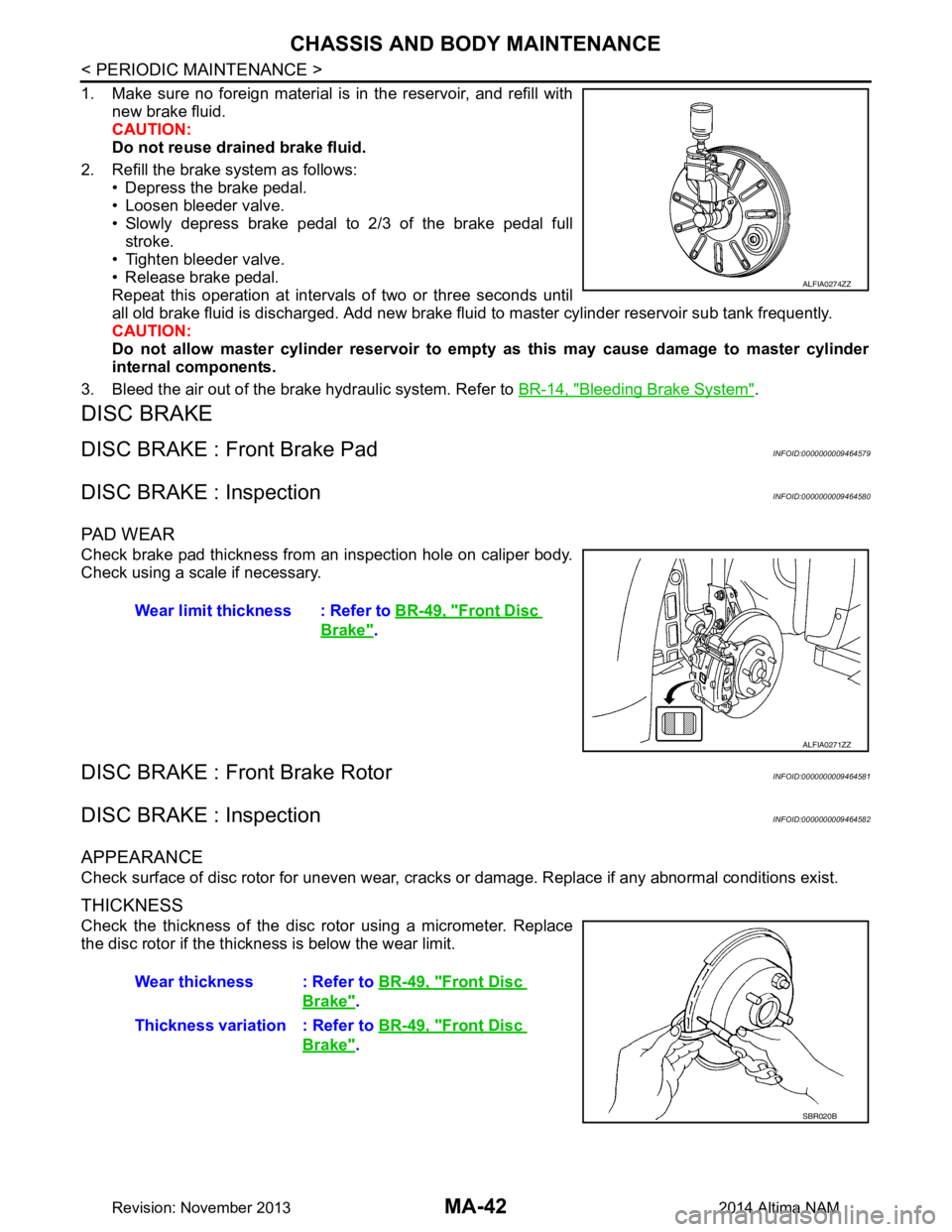
2. Refill the brake system as follows: • Depress the brake pedal.
• Loosen bleeder valve.
• Slowly depress brake pedal to 2/3 of the brake pedal full stroke.
• Tighten bleeder valve.
• Release brake pedal.
Repeat this operation at intervals of two or three seconds until
all old brake fluid is discharged. Add new brake flui d to master cylinder reservoir sub tank frequently.
CAUTION:
Do not allow master cylinder reservoir to empt y as this may cause damage to master cylinder
internal components.
3. Bleed the air out of the brake hydraulic system. Refer to BR-14, "Bleeding Brake System"
.
DISC BRAKE
DISC BRAKE : Front Brake PadINFOID:0000000009464579
DISC BRAKE : InspectionINFOID:0000000009464580
PA D W E A R
Check brake pad thickness from an inspection hole on caliper body.
Check using a scale if necessary.
DISC BRAKE : Front Brake RotorINFOID:0000000009464581
DISC BRAKE : InspectionINFOID:0000000009464582
APPEARANCE
Check surface of disc rotor for uneven wear, cracks or damage. Replace if any abnormal conditions exist.
THICKNESS
Check the thickness of the disc rotor using a micrometer. Replace
the disc rotor if the thickness is below the wear limit.
ALFIA0274ZZ
Wear limit thickness : Refer to BR-49, "Front Disc
Brake".
ALFIA0271ZZ
Wear thickness : Refer to BR-49, "Front Disc
Brake".
Thickness variation : Refer to BR-49, "Front Disc
Brake".
SBR020B
Revision: November 20132014 Altima NAM
Page 4105 of 4801

ST-2
Symptom Table ......................................................28
NOISE, VIBRATION AND HARSHNESS
(NVH) TROUBLESHOOTING ......................... ...
29
NVH Troubleshooting Chart ................................ ...29
PERIODIC MAINTENANCE ..................... ...30
POWER STEERING FLUID ............................ ...30
Draining and Refilling .......................................... ...30
Air Bleeding Hydraulic System ...............................30
REMOVAL AND INSTAL LATION ...............31
STEERING WHEEL ........................................ ...31
Exploded View ..................................................... ...31
Removal and Installation ........................................31
STEERING COLUMN ........................................33
Exploded View ..................................................... ...33
Removal and Installation ........................................33
STEERING GEAR AND LINKAGE ....................36
Exploded View ..................................................... ...36
Removal and Installation ........................................36
POWER STEERING OIL PUMP ........................38
Exploded View ..................................................... ...38
Removal and Installation .........................................38
HYDRAULIC LINE .......................................... ...40
Exploded View ..................................................... ...40
Removal and Installation .........................................41
UNIT DISASSEMBLY AND ASSEMBLY ...43
STEERING GEAR AND LINKAGE ................ ...43
Exploded View ..................................................... ...43
Disassembly and Assembly ....................................43
POWER STEERING OIL PUMP ........................45
Disassembly and Assembly ................................. ...45
SERVICE DATA AND SPECIFICATIONS
(SDS) ............... ...........................................
46
SERVICE DATA AND SPECIFICATIONS
(SDS) .............................................................. ...
46
Steering Wheel .................................................... ...46
Steering Angle ........................................................46
Steering Column .....................................................46
Power Steering Gear ..............................................47
Power Steering Oil Pump ........................................48
Power Steering Fluid ...............................................48
Revision: November 20132014 Altima NAMRevision: November 20132014 Altima NAM
Page 4122 of 4801

POWER STEERING OIL PUMPST-19
< BASIC INSPECTION >
C
D E
F
H I
J
K L
M A
B
ST
N
O P
POWER STEERING OIL PUMP
InspectionINFOID:0000000009461254
RELIEF OIL PRESSURE
CAUTION:
Make sure that belt tension is normal be fore starting the following procedure.
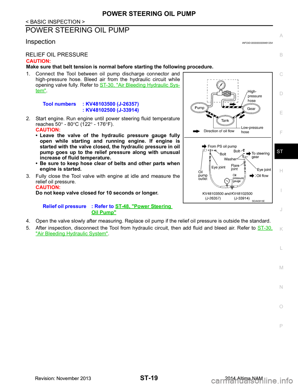
1. Connect the Tool between oil pump discharge connector and high-pressure hose. Bleed air from the hydraulic circuit while
opening valve fully. Refer to ST-30, "Air Bleeding Hydraulic Sys-
tem".
2. Start engine. Run engine until power steering fluid temperature reaches 50 ° - 80 °C (122 ° - 176 °F).
CAUTION:
• Leave the valve of the hydraulic pressure gauge fully open while starting and ru nning engine. If engine is
started with the valve closed, th e hydraulic pressure in oil
pump goes up to the relief pressure along with unusual
increase of fluid temperature.
• Be sure to keep hose clear of belts and other parts when engine is started.
3. Fully close the Tool valve with engine at idle and measure the relief oil pressure.
CAUTION:
Do not keep valve closed for 10 seconds or longer.
4. Open the valve slowly after measuring. Replace oil pump if the relief oil pressure is outside the standard.
5. After inspection, disconnect the Tool from hydraul ic circuit, then add fluid and bleed air. Refer to ST-30,
"Air Bleeding Hydraulic System".
Tool numbers : KV48103500 (J-26357)
: KV48102500 (J-33914)
Relief oil pressure : Refer to ST-48, "Power Steering
Oil Pump"
SGIA0915E
Revision: November 20132014 Altima NAMRevision: November 20132014 Altima NAM
Page 4133 of 4801

ST-30
< PERIODIC MAINTENANCE >
POWER STEERING FLUID
PERIODIC MAINTENANCE
POWER STEERING FLUID
Draining and RefillingINFOID:0000000009461266
DRAINING
1. Disconnect the high and low pressure piping from power steering gear.
2. Drain power steering fluid into a suitable container.
REFILLING
1. Fill power steering reservoir while checking power steering fluid level.
2. Bleed air from power steering hydraulic system. Refer to ST-30, "Air Bleeding Hydraulic System"
.
3. Check for power steering fluid leaks.
Air Bleeding Hydraulic SystemINFOID:0000000009461267
AIR BLEEDING HYDRAULIC SYSTEM
If air bleeding is not complete, excessive noise in the power steering oil pump will be present.
1. Make sure engine is off.
2. Turn the steering wheel from the full right stop pos ition and then to full left stop position several times.
Repeat until bubbles are no longer being generated in the reservoir.
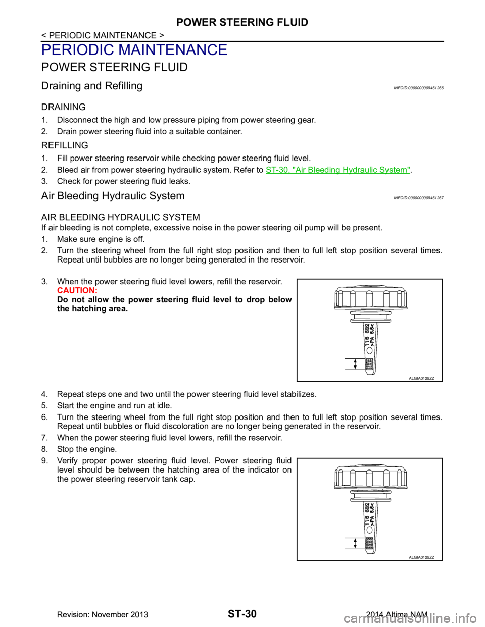
3. When the power steering fluid level lowers, refill the reservoir. CAUTION:
Do not allow the power steerin g fluid level to drop below
the hatching area.
4. Repeat steps one and two until the power steering fluid level stabilizes.
5. Start the engine and run at idle.
6. Turn the steering wheel from the full right stop pos ition and then to full left stop position several times.
Repeat until bubbles or fluid discoloration are no longer being generated in the reservoir.
7. When the power steering fluid level lowers, refill the reservoir.
8. Stop the engine.
9. Verify proper power steering fluid level. Power steering fluid level should be between the hatching area of the indicator on
the power steering reservoir tank cap.
ALGIA0125ZZ
ALGIA0125ZZ
Revision: November 20132014 Altima NAMRevision: November 20132014 Altima NAM