2014 NISSAN QUEST warning
[x] Cancel search: warningPage 95 of 482
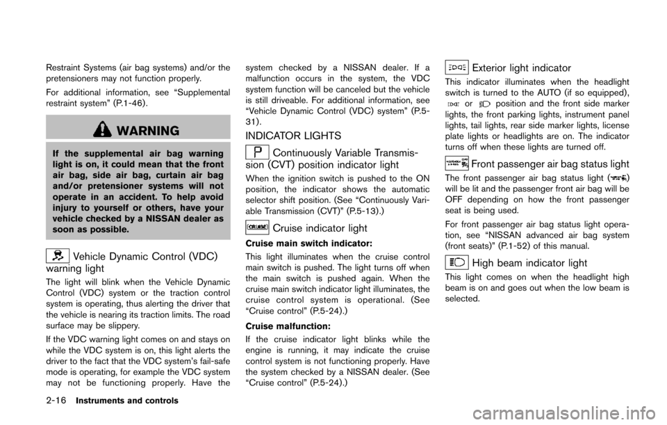
2-16Instruments and controls
Restraint Systems (air bag systems) and/or the
pretensioners may not function properly.
For additional information, see “Supplemental
restraint system” (P.1-46) .
WARNING
If the supplemental air bag warning
light is on, it could mean that the front
air bag, side air bag, curtain air bag
and/or pretensioner systems will not
operate in an accident. To help avoid
injury to yourself or others, have your
vehicle checked by a NISSAN dealer as
soon as possible.
Vehicle Dynamic Control (VDC)
warning light
The light will blink when the Vehicle Dynamic
Control (VDC) system or the traction control
system is operating, thus alerting the driver that
the vehicle is nearing its traction limits. The road
surface may be slippery.
If the VDC warning light comes on and stays on
while the VDC system is on, this light alerts the
driver to the fact that the VDC system’s fail-safe
mode is operating, for example the VDC system
may not be functioning properly. Have the system checked by a NISSAN dealer. If a
malfunction occurs in the system, the VDC
system function will be canceled but the vehicle
is still driveable. For additional information, see
“Vehicle Dynamic Control (VDC) system” (P.5-
31).
INDICATOR LIGHTS
Continuously Variable Transmis-
sion (CVT) position indicator light
When the ignition switch is pushed to the ON
position, the indicator shows the automatic
selector shift position. (See “Continuously Vari-
able Transmission (CVT)” (P.5-13) .)
Cruise indicator light
Cruise main switch indicator:
This light illuminates when the cruise control
main switch is pushed. The light turns off when
the main switch is pushed again. When the
cruise main switch indicator light illuminates, the
cruise control system is operational. (See
“Cruise control” (P.5-24).)
Cruise malfunction:
If the cruise indicator light blinks while the
engine is running, it may indicate the cruise
control system is not functioning properly. Have
the system checked by a NISSAN dealer. (See
“Cruise control” (P.5-24).)
Exterior light indicator
This indicator illuminates when the headlight
switch is turned to the AUTO (if so equipped) ,
orposition and the front side marker
lights, the front parking lights, instrument panel
lights, tail lights, rear side marker lights, license
plate lights or headlights are on. The indicator
turns off when these lights are turned off.
Front passenger air bag status light
The front passenger air bag status light ()
will be lit and the passenger front air bag will be
OFF depending on how the front passenger
seat is being used.
For front passenger air bag status light opera-
tion, see “NISSAN advanced air bag system
(front seats)” (P.1-52) of this manual.
High beam indicator light
This light comes on when the headlight high
beam is on and goes out when the low beam is
selected.
Page 96 of 482
Malfunction Indicator Light (MIL)
If the malfunction indicator light comes on
steady or blinks while the engine is running, it
may indicate a potential emission control and/or
Continuously Variable Transmission (CVT) mal-
function.
The malfunction indicator light may also come on
steady if the fuel-filler cap is loose or missing, or
if the vehicle runs out of fuel. Check to make
sure the fuel-filler cap is installed and closed
tightly, and that the vehicle has at least 3 US
gallons (11.4 liters) of fuel in the fuel tank.
After a few driving trips, the
light should
turn off if no other potential emission control
system malfunction exists.
If this indicator light remains on for 20 seconds
and then blinks for 10 seconds when the engine
is not running, it indicates that the vehicle is not
ready for an emission control system inspection/
maintenance test. (See “Readiness for inspec-
tion/maintenance (I/M) test” (P.9-27).)
Operation:
The malfunction indicator light will come on in
one of two ways:
. Malfunction indicator light on steady — An
emission control system and/or CVT mal-
function has been detected. Check the fuel-
filler cap if the LOOSE FUEL CAP warning appears on the dot matrix liquid crystal
display. If the fuel-filler cap is loose or
missing, tighten or install the cap and
continue to drive the vehicle. The
light
should turn off after a few driving trips. If the
light does not turn off after a few driving
trips, have the vehicle inspected by a
NISSAN dealer. You do not need to have
your vehicle towed to the dealer.
. Malfunction indicator light blinking — An
engine misfire has been detected which may
damage the emission control system.
To reduce or avoid emission control system
damage:
1) Do not drive at speeds above 45 MPH
(72 km/h).
2) Avoid hard acceleration or deceleration.
3) Avoid steep uphill grades.
4) If possible, reduce the amount of cargo being hauled or towed.
The malfunction indicator light may stop
blinking and remain on.
Have the vehicle inspected by a NISSAN
dealer. You do not need to have your vehicle
towed to the dealer.
CAUTION
Continued vehicle operation without
having the emission control system
and/or CVT system checked and re-
paired as necessary could lead to poor
driveability, reduced fuel economy, and
possible damage to the emission con-
trol system.
Overdrive off indicator light
The overdrive off indicator light illuminates when
the overdrive off mode is selected.
For additional information, see “Continuously
Variable Transmission (CVT)” (P.5-13) of this
manual.
Security indicator light
The light blinks when the ignition switch is in the
ACC, OFF or LOCK position. This function
indicates the security system equipped on the
vehicle is operational.
If the security system is malfunctioning, this light
will remain on while the ignition switch is in the
ON position. For additional information, see
“Security systems” (P.2-27) .
Instruments and controls2-17
Page 97 of 482
2-18Instruments and controls
Turn signal/hazard indicator lights
The light flashes when the turn signal switch
lever or hazard switch is turned on.
Vehicle Dynamic Control (VDC) off
indicator light
The light comes on when the vehicle dynamic
control off switch is pushed to OFF. This
indicates that the vehicle dynamic control
system and traction control system are not
operating.
AUDIBLE REMINDERS
Key reminder chime
A chime will sound if the driver side door is
opened while the ignition switch is pushed to
the ACC position. Make sure the ignition switch
is pushed to the OFF position, and take the
Intelligent Key with you when leaving the vehicle.
Light reminder chime
A chime will sound when the driver side door is
opened with the light switch in theorposition and the ignition switch in the ACC
or OFF position.
Turn the light switch off when you leave the
vehicle.
Models with Autolight system:
The chime will also sound for 2 seconds when the ignition switch is turned to the OFF position
with the fog lights on while the headlight switch
is in the AUTO position.
Parking brake reminder chime
The chime will sound if the vehicle is driven at
more than 4 MPH (7 km/h) with the parking
brake applied. Stop the vehicle and release the
parking brake.
Brake pad wear warning
The disc brake pads have audible wear warn-
ings. When a brake pad requires replacement, it
will make a high pitched scraping sound when
the vehicle is in motion. This scraping sound will
first occur only when the brake pedal is
depressed. After more wear of the brake pad,
the sound will always be heard even if the brake
pedal is not depressed. Have the brakes
checked as soon as possible if the warning
sound is heard.
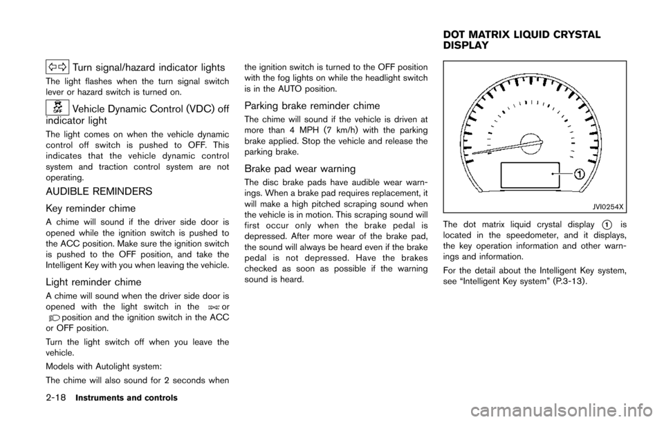
JVI0254X
The dot matrix liquid crystal display*1is
located in the speedometer, and it displays,
the key operation information and other warn-
ings and information.
For the detail about the Intelligent Key system,
see “Intelligent Key system” (P.3-13) .
DOT MATRIX LIQUID CRYSTAL
DISPLAY
Page 99 of 482
2-20Instruments and controls
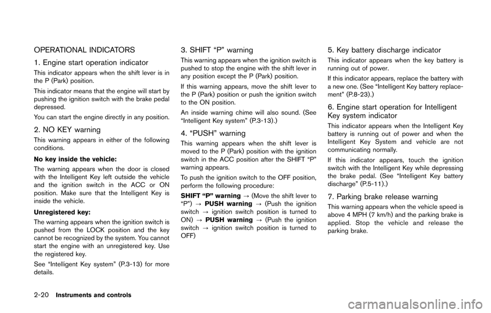
OPERATIONAL INDICATORS
1. Engine start operation indicator
This indicator appears when the shift lever is in
the P (Park) position.
This indicator means that the engine will start by
pushing the ignition switch with the brake pedal
depressed.
You can start the engine directly in any position.
2. NO KEY warning
This warning appears in either of the following
conditions.
No key inside the vehicle:
The warning appears when the door is closed
with the Intelligent Key left outside the vehicle
and the ignition switch in the ACC or ON
position. Make sure that the Intelligent Key is
inside the vehicle.
Unregistered key:
The warning appears when the ignition switch is
pushed from the LOCK position and the key
cannot be recognized by the system. You cannot
start the engine with an unregistered key. Use
the registered key.
See “Intelligent Key system” (P.3-13) for more
details.
3. SHIFT “P” warning
This warning appears when the ignition switch is
pushed to stop the engine with the shift lever in
any position except the P (Park) position.
If this warning appears, move the shift lever to
the P (Park) position or push the ignition switch
to the ON position.
An inside warning chime will also sound. (See
“Intelligent Key system” (P.3-13) .)
4. “PUSH” warning
This warning appears when the shift lever is
moved to the P (Park) position with the ignition
switch in the ACC position after the SHIFT “P”
warning appears.
To push the ignition switch to the OFF position,
perform the following procedure:
SHIFT “P” warning?(Move the shift lever to
“P”) ?PUSH warning ?(Push the ignition
switch ?ignition switch position is turned to
ON) ?PUSH warning ?(Push the ignition
switch ?ignition switch position is turned to
OFF)
5. Key battery discharge indicator
This indicator appears when the key battery is
running out of power.
If this indicator appears, replace the battery with
a new one. (See “Intelligent Key battery replace-
ment” (P.8-23) .)
6. Engine start operation for Intelligent
Key system indicator
This indicator appears when the Intelligent Key
battery is running out of power and when the
Intelligent Key System and vehicle are not
communicating normally.
If this indicator appears, touch the ignition
switch with the Intelligent Key while depressing
the brake pedal. (See “Intelligent Key battery
discharge” (P.5-11).)
7. Parking brake release warning
This warning appears when the vehicle speed is
above 4 MPH (7 km/h) and the parking brake is
applied. Stop the vehicle and release the
parking brake.
Page 100 of 482
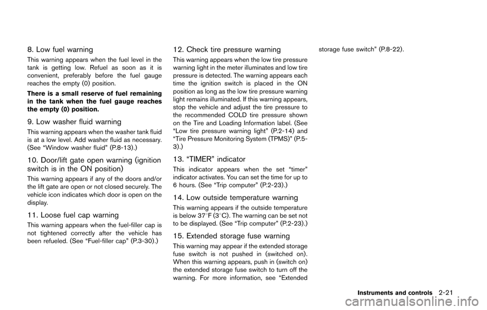
8. Low fuel warning
This warning appears when the fuel level in the
tank is getting low. Refuel as soon as it is
convenient, preferably before the fuel gauge
reaches the empty (0) position.
There is a small reserve of fuel remaining
in the tank when the fuel gauge reaches
the empty (0) position.
9. Low washer fluid warning
This warning appears when the washer tank fluid
is at a low level. Add washer fluid as necessary.
(See “Window washer fluid” (P.8-13).)
10. Door/lift gate open warning (ignition
switch is in the ON position)
This warning appears if any of the doors and/or
the lift gate are open or not closed securely. The
vehicle icon indicates which door is open on the
display.
11. Loose fuel cap warning
This warning appears when the fuel-filler cap is
not tightened correctly after the vehicle has
been refueled. (See “Fuel-filler cap” (P.3-30) .)
12. Check tire pressure warning
This warning appears when the low tire pressure
warning light in the meter illuminates and low tire
pressure is detected. The warning appears each
time the ignition switch is placed in the ON
position as long as the low tire pressure warning
light remains illuminated. If this warning appears,
stop the vehicle and adjust the tire pressure to
the recommended COLD tire pressure shown
on the Tire and Loading Information label. (See
“Low tire pressure warning light” (P.2-14) and
“Tire Pressure Monitoring System (TPMS)” (P.5-
3) .)
13. “TIMER” indicator
This indicator appears when the set “timer”
indicator activates. You can set the time for up to
6 hours. (See “Trip computer” (P.2-23) .)
14. Low outside temperature warning
This warning appears if the outside temperature
is below 378F(38C) . The warning can be set not
to be displayed. (See “Trip computer” (P.2-23) .)
15. Extended storage fuse warning
This warning may appear if the extended storage
fuse switch is not pushed in (switched on) .
When this warning appears, push in (switch on)
the extended storage fuse switch to turn off the
warning. For more information, see “Extended storage fuse switch” (P.8-22) .
Instruments and controls2-21
Page 101 of 482
2-22Instruments and controls
SIC4237
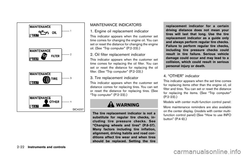
MAINTENANCE INDICATORS
1. Engine oil replacement indicator
This indicator appears when the customer set
time comes for changing the engine oil. You can
set or reset the distance for changing the engine
oil. (See “Trip computer” (P.2-23) .)
2. Oil filter replacement indicator
This indicator appears when the customer set
time comes for replacing the oil filter. You can
set or reset the distance for replacing the oil
filter. (See “Trip computer” (P.2-23).)
3. Tire replacement indicator
This indicator appears when the customer set
distance comes for replacing tires. You can set
or reset the distance for replacing tires. (See
“Trip computer” (P.2-23) .)
WARNING
The tire replacement indicator is not a
substitute for regular tire checks, in-
cluding tire pressure checks. See
“Changing wheels and tires” (P.8-37) .
Many factors including tire inflation,
alignment, driving habits and road con-
ditions affect tire wear and when tires
should be replaced. Setting the tirereplacement indicator for a certain
driving distance does not mean your
tires will last that long. Use the tire
replacement indicator as a guide only
and always perform regular tire checks.
Failure to perform regular tire checks,
including tire pressure checks could
result in tire failure. Serious vehicle
damage could occur and may lead to a
collision, which could result in serious
personal injury or death.
4. “OTHER” indicator
This indicator appears when the set time comes
for replacing items other than the engine oil, oil
filter and tires. You can set or reset the distance
for replacing the items. (See “Trip computer”
(P.2-23) .)
Models with center multi-function control panel:
More maintenance reminders are also available
on the center display. (models with center multi-
function control panel) (See “How to use INFO
button” (P.4-9).)
Page 102 of 482
SIC3580
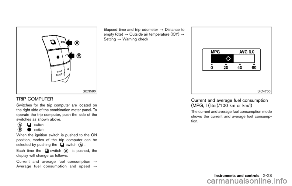
TRIP COMPUTER
Switches for the trip computer are located on
the right side of the combination meter panel. To
operate the trip computer, push the side of the
switches as shown above.
*Aswitch
*Bswitch
When the ignition switch is pushed to the ON
position, modes of the trip computer can be
selected by pushing the
switch*A.
Each time the
switch*Ais pushed, the
display will change as follows:
Current and average fuel consumption ?
Average fuel consumption and speed ?Elapsed time and trip odometer
?Distance to
empty (dte) ?Outside air temperature (ICY) ?
Setting ?Warning check
SIC4700
Current and average fuel consumption
(MPG, l (liter)/100 km or km/l)
The current and average fuel consumption mode
shows the current and average fuel consump-
tion.
Instruments and controls2-23
Page 104 of 482
SIC4702
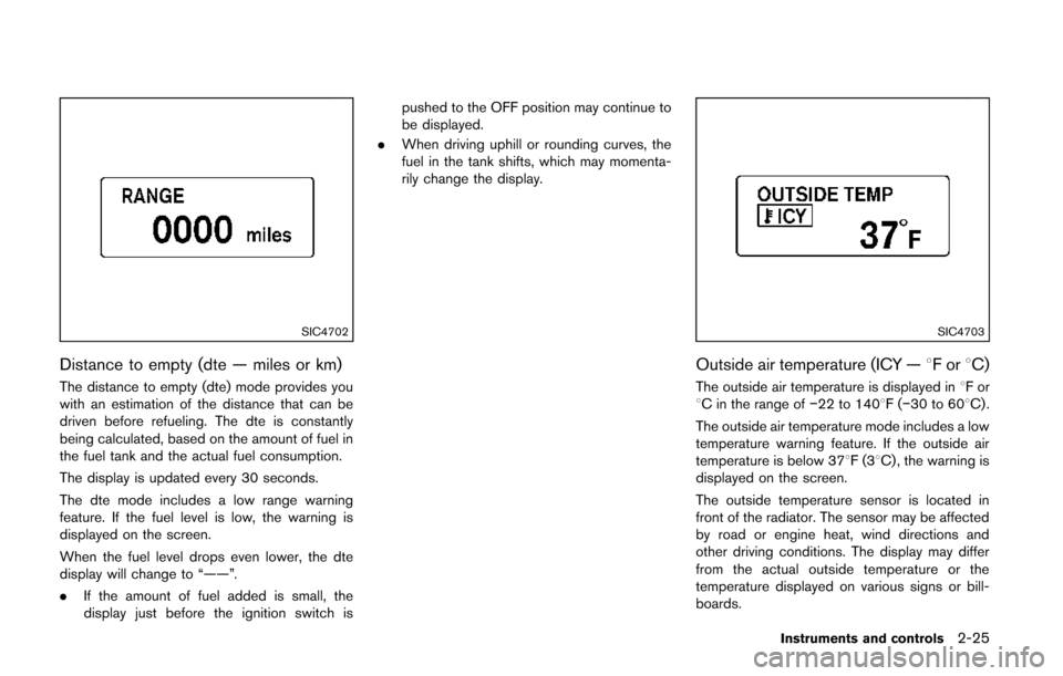
Distance to empty (dte — miles or km)
The distance to empty (dte) mode provides you
with an estimation of the distance that can be
driven before refueling. The dte is constantly
being calculated, based on the amount of fuel in
the fuel tank and the actual fuel consumption.
The display is updated every 30 seconds.
The dte mode includes a low range warning
feature. If the fuel level is low, the warning is
displayed on the screen.
When the fuel level drops even lower, the dte
display will change to “——”.
.If the amount of fuel added is small, the
display just before the ignition switch is pushed to the OFF position may continue to
be displayed.
. When driving uphill or rounding curves, the
fuel in the tank shifts, which may momenta-
rily change the display.
SIC4703
Outside air temperature (ICY — 8For8C)
The outside air temperature is displayed in 8For
8C in the range of −22 to 1408F(−30 to 608C) .
The outside air temperature mode includes a low
temperature warning feature. If the outside air
temperature is below 378F(3 8C) , the warning is
displayed on the screen.
The outside temperature sensor is located in
front of the radiator. The sensor may be affected
by road or engine heat, wind directions and
other driving conditions. The display may differ
from the actual outside temperature or the
temperature displayed on various signs or bill-
boards.
Instruments and controls2-25