Page 102 of 482
SIC3580
TRIP COMPUTER
Switches for the trip computer are located on
the right side of the combination meter panel. To
operate the trip computer, push the side of the
switches as shown above.
*Aswitch
*Bswitch
When the ignition switch is pushed to the ON
position, modes of the trip computer can be
selected by pushing the
switch*A.
Each time the
switch*Ais pushed, the
display will change as follows:
Current and average fuel consumption ?
Average fuel consumption and speed ?Elapsed time and trip odometer
?Distance to
empty (dte) ?Outside air temperature (ICY) ?
Setting ?Warning check
SIC4700
Current and average fuel consumption
(MPG, l (liter)/100 km or km/l)
The current and average fuel consumption mode
shows the current and average fuel consump-
tion.
Instruments and controls2-23
Page 108 of 482
by releasing the door inside lock knob, the
alarm will activate.)
How to stop an activated alarm
The alarm will stop by unlocking a door by
pushing the unlock button on the Intelligent Key,
the door handle request switch or using the
mechanical key. The alarm will not stop if the
ignition switch is pushed to the ACC or ON
position.
If the system does not operate as de-
scribed above, have it checked by a
NISSAN dealer.
NISSAN VEHICLE IMMOBILIZER SYS-
TEM
The NISSAN Vehicle Immobilizer System will not
allow the engine to start without the use of the
registered Intelligent Key.Never leave these
keys in the vehicle.
FCC Notice:
For USA:
This device complies with Part 15 of the
FCC Rules. Operation is subject to the
following two conditions:
(1) This device may not cause harmful
interference, and (2) this device must
accept any interference received, including
interference that may cause undesired operation.
Note: Changes or modifications not ex-
pressly approved by the party responsible
for compliance could void the user’s
authority to operate the equipment.
For Canada:
This device complies with RSS-210 of
Industry Canada. Operation is subject to
the following two conditions:
(1) this device may not cause interference,
and (2) this device must accept any inter-
ference, including interference that may
cause undesired operation of the device.
SIC2045
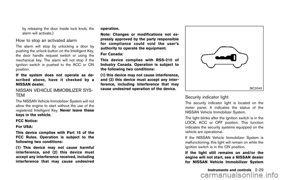
Security indicator light
The security indicator light is located on the
meter panel. It indicates the status of the
NISSAN Vehicle Immobilizer System.
The light blinks after the ignition switch is in the
LOCK, ACC or OFF position. This function
indicates the security systems equipped on the
vehicle are operational.
If the NISSAN Vehicle Immobilizer System is
malfunctioning, this light will remain on while the
ignition switch is in the ON position.
If the light still remains on and/or the
engine will not start, see a NISSAN dealer
for NISSAN Vehicle Immobilizer System
Instruments and controls2-29
Page 110 of 482
SIC3664
The windshield wiper and washer operates
when the ignition switch is in the ON position.
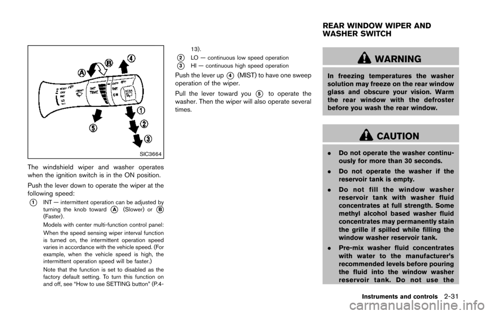
Push the lever down to operate the wiper at the
following speed:
*1INT — intermittent operation can be adjusted by
turning the knob toward*A(Slower) or*B(Faster) .
Models with center multi-function control panel:
When the speed sensing wiper interval function
is turned on, the intermittent operation speed
varies in accordance with the vehicle speed. (For
example, when the vehicle speed is high, the
intermittent operation speed will be faster.)
Note that the function is set to disabled as the
factory default setting. To turn this function on
and off, see “How to use SETTING button” (P.4-13).
*2LO — continuous low speed operation
*3HI — continuous high speed operation
Push the lever up*4(MIST) to have one sweep
operation of the wiper.
Pull the lever toward you
*5to operate the
washer. Then the wiper will also operate several
times.
WARNING
In freezing temperatures the washer
solution may freeze on the rear window
glass and obscure your vision. Warm
the rear window with the defroster
before you wash the rear window.
CAUTION
. Do not operate the washer continu-
ously for more than 30 seconds.
. Do not operate the washer if the
reservoir tank is empty.
. Do not fill the window washer
reservoir tank with washer fluid
concentrates at full strength. Some
methyl alcohol based washer fluid
concentrates may permanently stain
the grille if spilled while filling the
window washer reservoir tank.
. Pre-mix washer fluid concentrates
with water to the manufacturer’s
recommended levels before pouring
the fluid into the window washer
reservoir tank. Do not use the
Instruments and controls2-31
REAR WINDOW WIPER AND
WASHER SWITCH
Page 113 of 482
2-34Instruments and controls
SIC3669
Autolight system (if so equipped)
The autolight system allows the headlights to be
set so they turn on and off automatically.
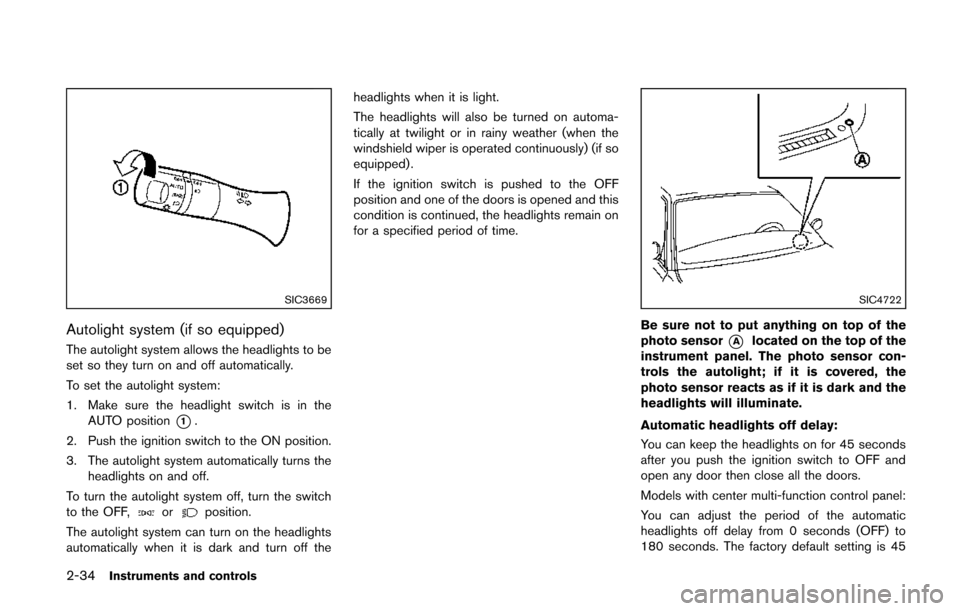
To set the autolight system:
1. Make sure the headlight switch is in theAUTO position
*1.
2. Push the ignition switch to the ON position.
3. The autolight system automatically turns the headlights on and off.
To turn the autolight system off, turn the switch
to the OFF,
orposition.
The autolight system can turn on the headlights
automatically when it is dark and turn off the headlights when it is light.
The headlights will also be turned on automa-
tically at twilight or in rainy weather (when the
windshield wiper is operated continuously) (if so
equipped) .
If the ignition switch is pushed to the OFF
position and one of the doors is opened and this
condition is continued, the headlights remain on
for a specified period of time.
SIC4722
Be sure not to put anything on top of the
photo sensor
*Alocated on the top of the
instrument panel. The photo sensor con-
trols the autolight; if it is covered, the
photo sensor reacts as if it is dark and the
headlights will illuminate.
Automatic headlights off delay:
You can keep the headlights on for 45 seconds
after you push the ignition switch to OFF and
open any door then close all the doors.
Models with center multi-function control panel:
You can adjust the period of the automatic
headlights off delay from 0 seconds (OFF) to
180 seconds. The factory default setting is 45
Page 114 of 482
seconds.
For automatic headlights off delay setting, see
“Vehicle information and settings (models with
center multi-function control panel)” (P.4-8).
SIC3670
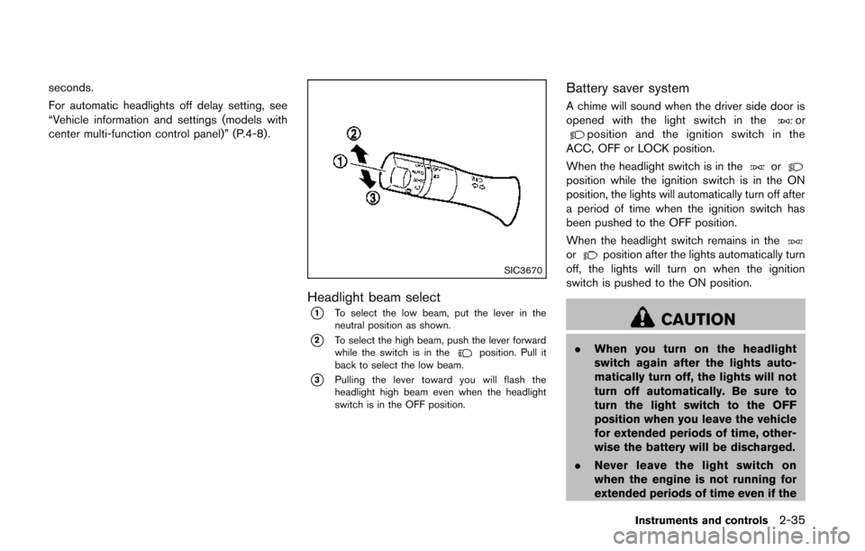
Headlight beam select
*1To select the low beam, put the lever in the
neutral position as shown.
*2To select the high beam, push the lever forward
while the switch is in theposition. Pull it
back to select the low beam.
*3Pulling the lever toward you will flash the
headlight high beam even when the headlight
switch is in the OFF position.
Battery saver system
A chime will sound when the driver side door is
opened with the light switch in theorposition and the ignition switch in the
ACC, OFF or LOCK position.
When the headlight switch is in the
orposition while the ignition switch is in the ON
position, the lights will automatically turn off after
a period of time when the ignition switch has
been pushed to the OFF position.
When the headlight switch remains in the
orposition after the lights automatically turn
off, the lights will turn on when the ignition
switch is pushed to the ON position.
CAUTION
. When you turn on the headlight
switch again after the lights auto-
matically turn off, the lights will not
turn off automatically. Be sure to
turn the light switch to the OFF
position when you leave the vehicle
for extended periods of time, other-
wise the battery will be discharged.
. Never leave the light switch on
when the engine is not running for
extended periods of time even if the
Instruments and controls2-35
Page 116 of 482
running lights will remain on until the ignition
switch is pushed to the OFF position.
WARNING
When the daytime running light system
is active, tail lights on your vehicle are
not on. It is necessary at dusk to turn on
your headlights. Failure to do so could
cause an accident injuring yourself and
others.
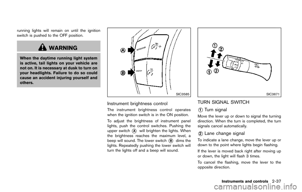
SIC3585
Instrument brightness control
The instrument brightness control operates
when the ignition switch is in the ON position.
To adjust the brightness of instrument panel
lights, push the control switches. Pushing the
upper switch
*Awill brighten the lights. When
the brightness reaches the maximum level, a
beep will sound. The lower switch
*Bdims the
lights. Repeatedly pushing the lower switch will
turn the lights off and a beep will sound.
SIC3671
TURN SIGNAL SWITCH
*1Turn signal
Move the lever up or down to signal the turning
direction. When the turn is completed, the turn
signals cancel automatically.
*2Lane change signal
To indicate a lane change, move the lever up or
down to the point where lights begin flashing.
If the lever is moved back right after moving up
or down, the light will flash 3 times.
To cancel the flashing, move the lever to the
opposite direction.
Instruments and controls2-37
Page 118 of 482
damage to the heater.
. Any liquid spilled on the heated seat
should be removed immediately
with a dry cloth.
. When cleaning the seat, never use
gasoline, thinner, or any similar
materials.
. If any malfunctions are found or the
heated seat does not operate, turn
the switch off and have the system
checked by a NISSAN dealer.
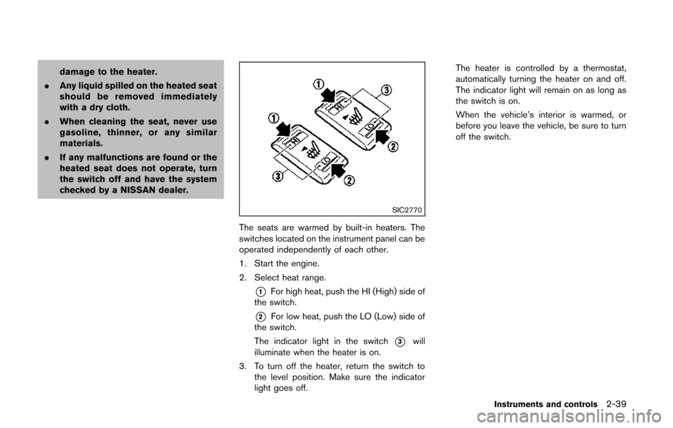
SIC2770
The seats are warmed by built-in heaters. The
switches located on the instrument panel can be
operated independently of each other.
1. Start the engine.
2. Select heat range.
*1For high heat, push the HI (High) side of
the switch.
*2For low heat, push the LO (Low) side of
the switch.
The indicator light in the switch
*3will
illuminate when the heater is on.
3. To turn off the heater, return the switch to the level position. Make sure the indicator
light goes off. The heater is controlled by a thermostat,
automatically turning the heater on and off.
The indicator light will remain on as long as
the switch is on.
When the vehicle’s interior is warmed, or
before you leave the vehicle, be sure to turn
off the switch.
Instruments and controls2-39
Page 120 of 482
CAUTION
.Use power outlet with the engine
running to avoid discharging the
vehicle battery.
. Avoid using power outlet when the
air conditioner, headlights or rear
window defroster is on.
. Before inserting or disconnecting a
plug, be sure the electrical acces-
sory being used is turned OFF.
. When not in use, be sure to close
the cap. Do not allow water or any
liquid to contact the outlet.
SIC4723Instrument panel
SIC4724Cargo area
Type A
To use the power outlet, pull the cover as
illustrated.
CAUTION
.The outlet and plug may be hot
during or immediately after use.
. Do not use with accessories that
exceed a 12 volt, 120W (10A) power
draw. Do not use double adapters or
more than one electrical accessory.
. This power outlet is not designed
for use with a cigarette lighter unit.
. Push the plug in as far as it will go.
If good contact is not made, the plug
may overheat or the internal tem-
perature fuse may open.
Instruments and controls2-41
POWER OUTLET