2014 NISSAN QUEST check engine light
[x] Cancel search: check engine lightPage 163 of 482
3-20Pre-driving checks and adjustments
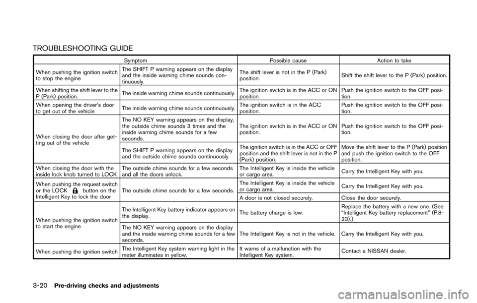
TROUBLESHOOTING GUIDE
SymptomPossible causeAction to take
When pushing the ignition switch
to stop the engine The SHIFT P warning appears on the display
and the inside warning chime sounds con-
tinuously.
The shift lever is not in the P (Park)
position.
Shift the shift lever to the P (Park) position.
When shifting the shift lever to the
P (Park) position. The inside warning chime sounds continuously.
The ignition switch is in the ACC or ON
position.Push the ignition switch to the OFF posi-
tion.
When opening the driver’s door
to get out of the vehicle The inside warning chime sounds continuously. The ignition switch is in the ACC
position.Push the ignition switch to the OFF posi-
tion.
When closing the door after get-
ting out of the vehicle The NO KEY warning appears on the display,
the outside chime sounds 3 times and the
inside warning chime sounds for a few
seconds.
The ignition switch is in the ACC or ON
position.
Push the ignition switch to the OFF posi-
tion.
The SHIFT P warning appears on the display
and the outside chime sounds continuously. The ignition switch is in the ACC or OFF
position and the shift lever is not in the P
(Park) position.Move the shift lever to the P (Park) position
and push the ignition switch to the OFF
position.
When closing the door with the
inside lock knob turned to LOCK The outside chime sounds for a few seconds
and all the doors unlock. The Intelligent Key is inside the vehicle
or cargo area.
Carry the Intelligent Key with you.
When pushing the request switch
or the LOCK
button on the
Intelligent Key to lock the door The outside chime sounds for a few seconds. The Intelligent Key is inside the vehicle
or cargo area.
Carry the Intelligent Key with you.
A door is not closed securely. Close the door securely.
When pushing the ignition switch
to start the engine The Intelligent Key battery indicator appears on
the display.
The battery charge is low.Replace the battery with a new one. (See
“Intelligent Key battery replacement” (P.8-
23).)
The NO KEY warning appears on the display
and the inside warning chime sounds for a few
seconds. The Intelligent Key is not in the vehicle. Carry the Intelligent Key with you.
When pushing the ignition switch The Intelligent Key system warning light in the
meter illuminates in yellow. It warns of a malfunction with the
Intelligent Key system.
Contact a NISSAN dealer.
Page 168 of 482
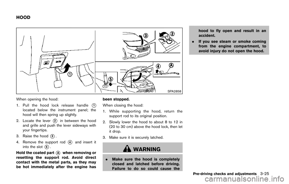
SPA2858
When opening the hood:
1. Pull the hood lock release handle
*1located below the instrument panel; the
hood will then spring up slightly.
2. Locate the lever
*2in between the hood
and grille and push the lever sideways with
your fingertips.
3. Raise the hood
*3.
4. Remove the support rod
*4and insert it
into the slot
*5.
Hold the coated part
*Awhen removing or
resetting the support rod. Avoid direct
contact with the metal parts, as they may
be hot immediately after the engine has been stopped.
When closing the hood:
1. While supporting the hood, return the
support rod to its original position.
2. Slowly lower the hood to about 8 to 12 in (20 to 30 cm) above the hood lock, then let
it drop.
3. Make sure it is securely latched.WARNING
. Make sure the hood is completely
closed and latched before driving.
Failure to do so could cause the hood to fly open and result in an
accident.
. If you see steam or smoke coming
from the engine compartment, to
avoid injury do not open the hood.
Pre-driving checks and adjustments3-25
HOOD
Page 173 of 482
3-30Pre-driving checks and adjustments
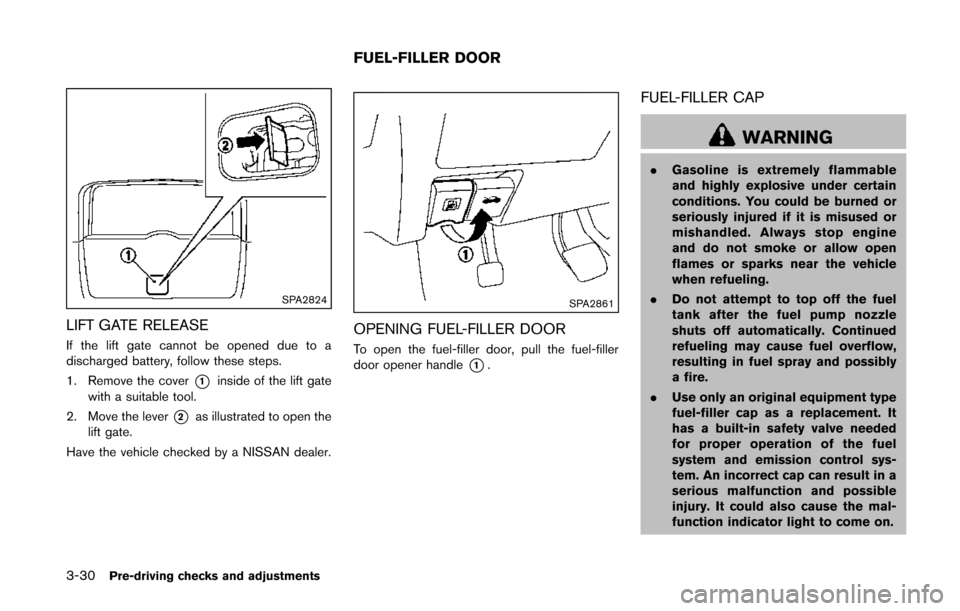
SPA2824
LIFT GATE RELEASE
If the lift gate cannot be opened due to a
discharged battery, follow these steps.
1. Remove the cover
*1inside of the lift gate
with a suitable tool.
2. Move the lever
*2as illustrated to open the
lift gate.
Have the vehicle checked by a NISSAN dealer.
SPA2861
OPENING FUEL-FILLER DOOR
To open the fuel-filler door, pull the fuel-filler
door opener handle
*1.
FUEL-FILLER CAP
WARNING
. Gasoline is extremely flammable
and highly explosive under certain
conditions. You could be burned or
seriously injured if it is misused or
mishandled. Always stop engine
and do not smoke or allow open
flames or sparks near the vehicle
when refueling.
. Do not attempt to top off the fuel
tank after the fuel pump nozzle
shuts off automatically. Continued
refueling may cause fuel overflow,
resulting in fuel spray and possibly
a fire.
. Use only an original equipment type
fuel-filler cap as a replacement. It
has a built-in safety valve needed
for proper operation of the fuel
system and emission control sys-
tem. An incorrect cap can result in a
serious malfunction and possible
injury. It could also cause the mal-
function indicator light to come on.
FUEL-FILLER DOOR
Page 181 of 482
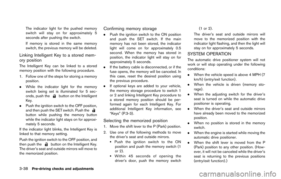
3-38Pre-driving checks and adjustments
The indicator light for the pushed memory
switch will stay on for approximately 5
seconds after pushing the switch.
If memory is stored in the same memory
switch, the previous memory will be deleted.
Linking Intelligent Key to a stored mem-
ory position
The Intelligent Key can be linked to a stored
memory position with the following procedure.
1. Follow one of the steps for storing a memoryposition.
. While the indicator light for the memory
switch being set is illuminated for 5 sec-
onds, push the
button on the Intelligent
Key.
. Push the ignition switch to the OFF position,
and then push the SET switch. Push the
button while pushing the memory button
while the indicator light stays on for approxi-
mately 5 seconds.
If the indicator light blinks, the Intelligent Key is
linked to that memory setting.
Push the ignition switch to the OFF position, and
then push the
button on the Intelligent Key.
The driver’s seat and outside mirrors will move to
the memorized position.
Confirming memory storage
. Push the ignition switch to the ON position
and push the SET switch. If the main
memory has not been stored, the indicator
light will come on for approximately 0.5
second. When the memory has stored in
position, the indicator light will stay on for
approximately 5 seconds.
. If the battery cable is disconnected, or if the
fuse opens, the memory will be canceled. In
this case, reset the desired position using
the previous procedure.
. If optional keys are added to your vehicle,
the memory storage procedure to switch 1
or 2 and linking Intelligent Key procedure to
a stored memory position should be per-
formed again for each Intelligent Key. For
additional Intelligent Key information, see
“Keys” (P.3-3) .
Selecting the memorized position
1. Move the shift lever to the P (Park) position.
2. Use one of the following methods to move
the driver’s seat and outside mirrors.
.Push the ignition switch to the ONposition and push the memory switch (1
or 2) .
.Within 45 seconds of opening thedriver’s door, push the memory switch (1 or 2) .
The driver’s seat and outside mirrors will
move to the memorized position with the
indicator light flashing, and then the light will
stay on for approximately 5 seconds.
SYSTEM OPERATION
The automatic drive positioner system will not
work or will stop operating under the following
conditions:
. When the vehicle speed is above 4 MPH (7
km/h) (entry/exit function) .
. When the vehicle is driven (memory sto-
rage).
. When the adjusting switch for the driver’s
seat is turned on while the automatic drive
positioner is operating.
. When the driver’s seat and outside mirrors
have already been moved to the memorized
position.
. When no position is stored in the memory
switch.
. When the engine is started while moving the
automatic drive positioner.
. When the shift lever is moved from the P
(Park) position to any other position. (How-
ever, it will not be canceled while the driver’s
seat is returning to the previous positions
(entry/exit function).)
Page 355 of 482
5-12Starting and driving
.Make sure the area around the vehicle is
clear.
. Check fluid levels such as engine oil, cool-
ant, brake fluid and window washer fluid as
frequently as possible, or at least whenever
you refuel.
. Check that all windows and lights are clean.
. Visually inspect tires for their appearance
and condition. Also check tires for proper
inflation.
. Lock all doors.
. Position seats and adjust head restraints/
headrests.
. Adjust inside and outside mirrors.
. Fasten seat belts and ask all passengers to
do likewise.
. Check the operation of warning lights when
the ignition switch is pushed to the ON
position. (See “Warning/indicator lights and
audible reminders” (P.2-11) .) 1. Apply the parking brake.
2. Move the shift lever to the P (Park) or N
(Neutral) position. (P is recommended.)
The starter is designed not to operate unless
the shift lever is in either of the above
positions.
3. Push the ignition switch to the ON position. Depress the brake pedal and push the
ignition switch to start the engine.
To start the engine immediately, push and
release the ignition switch while depressing
the brake pedal with the ignition switch in
any position.
.If the engine is very hard to start inextremely cold weather or when restart-
ing, depress the accelerator pedal a little
(approximately 1/3 to the floor) and while
holding, crank the engine. Release the
accelerator pedal when the engine starts.
.If the engine is very hard to start becauseit is flooded, depress the accelerator
pedal all the way to the floor and hold it.
Push the ignition switch to the ON
position to start cranking the engine.
After 5 or 6 seconds, stop cranking by
pushing the ignition switch to OFF. After
cranking the engine, release the accel-
erator pedal. Crank the engine with your
foot off the accelerator pedal bydepressing the brake pedal and pushing
the push-button ignition switch to start
the engine. If the engine starts, but fails
to run, repeat the above procedure.
CAUTION
Do not operate the starter for more
than 15 seconds at a time. If the engine
does not start, push the ignition switch
to OFF and wait 10 seconds before
cranking again, otherwise the starter
could be damaged.
4. Warm-up
Allow the engine to idle for at least 30
seconds after starting. Do not race the
engine while warming it up. Drive at
moderate speed for a short distance first,
especially in cold weather. In cold weather,
keep the engine running for a minimum of 2 -
3 minutes before shutting it off. Starting and
stopping the engine over a short period of
time may make the vehicle more difficult to
start.
5. To stop the engine, shift the shift lever to the P (Park) position and push the ignition
switch to the OFF position.
BEFORE STARTING THE ENGINE STARTING THE ENGINE
Page 359 of 482
5-16Starting and driving
ing condition. If it does not return to its
normal operating condition, have a
NISSAN dealer check the transmission
and repair if necessary.
WARNING
When the high fluid temperature pro-
tection mode or fail-safe operation
occurs, vehicle speed may be gradually
reduced. The reduced speed may be
lower than other traffic, which could
increase the chance of a collision. Be
especially careful when driving. If ne-
cessary, pull to the side of the road at a
safe place and allow the transmission
to return to normal operation, or have it
repaired if necessary.
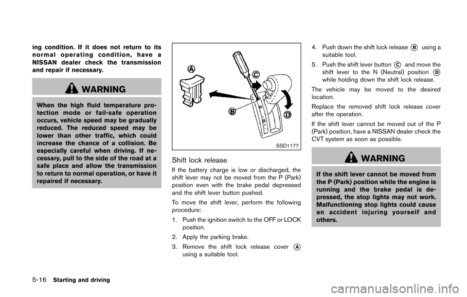
SSD1177
Shift lock release
If the battery charge is low or discharged, the
shift lever may not be moved from the P (Park)
position even with the brake pedal depressed
and the shift lever button pushed.
To move the shift lever, perform the following
procedure:
1. Push the ignition switch to the OFF or LOCKposition.
2. Apply the parking brake.
3. Remove the shift lock release cover
*Ausing a suitable tool. 4. Push down the shift lock release
*Busing a
suitable tool.
5. Push the shift lever button
*Cand move the
shift lever to the N (Neutral) position
*Dwhile holding down the shift lock release.
The vehicle may be moved to the desired
location.
Replace the removed shift lock release cover
after the operation.
If the shift lever cannot be moved out of the P
(Park) position, have a NISSAN dealer check the
CVT system as soon as possible.
WARNING
If the shift lever cannot be moved from
the P (Park) position while the engine is
running and the brake pedal is de-
pressed, the stop lights may not work.
Malfunctioning stop lights could cause
an accident injuring yourself and
others.
Page 366 of 482
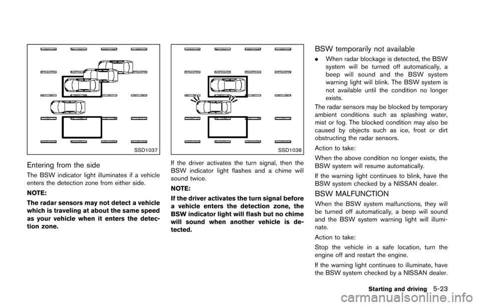
SSD1037
Entering from the side
The BSW indicator light illuminates if a vehicle
enters the detection zone from either side.
NOTE:
The radar sensors may not detect a vehicle
which is traveling at about the same speed
as your vehicle when it enters the detec-
tion zone.
SSD1038
If the driver activates the turn signal, then the
BSW indicator light flashes and a chime will
sound twice.
NOTE:
If the driver activates the turn signal before
a vehicle enters the detection zone, the
BSW indicator light will flash but no chime
will sound when another vehicle is de-
tected.
BSW temporarily not available
.When radar blockage is detected, the BSW
system will be turned off automatically, a
beep will sound and the BSW system
warning light will blink. The BSW system is
not available until the condition no longer
exists.
The radar sensors may be blocked by temporary
ambient conditions such as splashing water,
mist or fog. The blocked condition may also be
caused by objects such as ice, frost or dirt
obstructing the radar sensors.
Action to take:
When the above condition no longer exists, the
BSW system will resume automatically.
If the warning light continues to blink, have the
BSW system checked by a NISSAN dealer.
BSW MALFUNCTION
When the BSW system malfunctions, they will
be turned off automatically, a beep will sound
and the BSW system warning light will illumi-
nate.
Action to take:
Stop the vehicle in a safe location, turn the
engine off and restart the engine.
If the warning light continues to illuminate, have
the BSW system checked by a NISSAN dealer.
Starting and driving5-23
Page 367 of 482
5-24Starting and driving
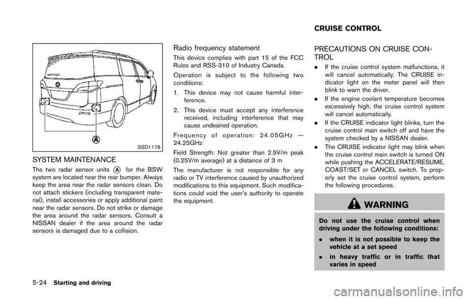
SSD1178
SYSTEM MAINTENANCE
The two radar sensor units*Afor the BSW
system are located near the rear bumper. Always
keep the area near the radar sensors clean. Do
not attach stickers (including transparent mate-
rial) , install accessories or apply additional paint
near the radar sensors. Do not strike or damage
the area around the radar sensors. Consult a
NISSAN dealer if the area around the radar
sensors is damaged due to a collision.
Radio frequency statement
This device complies with part 15 of the FCC
Rules and RSS-310 of Industry Canada.
Operation is subject to the following two
conditions:
1. This device may not cause harmful inter- ference.
2. This device must accept any interference received, including interference that may
cause undesired operation.
Frequency of operation: 24.05GHz —
24.25GHz
Field Strength: Not greater than 2.5V/m peak
(0.25V/m average) at a distance of 3 m
The manufacturer is not responsible for any
radio or TV interference caused by unauthorized
modifications to this equipment. Such modifica-
tions could void the user’s authority to operate
the equipment.
PRECAUTIONS ON CRUISE CON-
TROL
. If the cruise control system malfunctions, it
will cancel automatically. The CRUISE in-
dicator light on the meter panel will then
blink to warn the driver.
. If the engine coolant temperature becomes
excessively high, the cruise control system
will cancel automatically.
. If the CRUISE indicator light blinks, turn the
cruise control main switch off and have the
system checked by a NISSAN dealer.
. The CRUISE indicator light may blink when
the cruise control main switch is turned ON
while pushing the ACCELERATE/RESUME,
COAST/SET or CANCEL switch. To prop-
erly set the cruise control system, perform
the following procedures.
WARNING
Do not use the cruise control when
driving under the following conditions:
. when it is not possible to keep the
vehicle at a set speed
. in heavy traffic or in traffic that
varies in speed
CRUISE CONTROL