2014 NISSAN QASHQAI spare wheel
[x] Cancel search: spare wheelPage 235 of 338

Driving downhill
The engine braking action is effective for controlling
the vehicle while descending hills.
The shift lever (MT models) should be placed in a
gear position low enough to obtain sufficient engine
braking.
For XTRONIC transmission models, a low gear po-
sition in the manual shift mode, low enough to obtain
sufficient engine braking, should be selected.WARNING
•The Anti-lock Braking System (ABS) is a so-
phisticated device, but it cannot prevent acci-
dents resulting from careless or dangerous
driving techniques. It can help maintain ve-
hicle control during braking on slippery sur-
faces. Remember that stopping distances on
slippery surfaces will be longer than on nor-
mal surfaces even with ABS. Stopping dis-
tances may also be longer on rough, gravel or
snow covered roads, or if you are using snow
chains. Always maintain a safe distance from
the vehicle in front of you. Ultimately, the
driver is responsible for safety.
•Tyre type and condition may also affect brak-
ing effectiveness.
– When replacing tyres, install the specified
size of tyres on all four wheels.
– When installing a spare tyre, make sure
that it is the proper size and type as speci-
fied on the tyre placard. (See “Vehicle
identification” in the “9. Technical
information” section.)
– For detailed information, see “Wheels and
tyres” in the “8. Maintenance and
do-it-yourself” section.
The Anti-lock Braking System (ABS) controls the
brakes so the wheels do not lock during hard brak-
ing or when braking on slippery surfaces. The sys-
tem detects the rotation speed at each wheel and
varies the brake fluid pressure to prevent each wheelfrom locking and sliding. By preventing each wheel
from locking, the system helps the driver maintain
steering control and helps to minimise swerving and
spinning on slippery surfaces.
USING SYSTEM
Depress the brake pedal and hold it down. Depress
the brake pedal with firm steady pressure, but do
not pump the brakes. The ABS will operate to pre-
vent the wheels from locking up. Steer the vehicle to
avoid obstacles.
WARNING
Do not pump the brake pedal. Doing so may re-
sult in increased stopping distances.
SELF-TEST FEATURE
The ABS includes electronic sensors, electric
pumps, hydraulic solenoids and a computer. The
computer has a built-in diagnostic feature that tests
the system each time you start the engine and move
the vehicle at a low speed in forward or reverse.
When the self-test occurs, you may hear a “clunk”
noise and/or feel a pulsation in the brake pedal. This
is normal and does not indicate a malfunction. If the
computer senses a malfunction, it switches the ABS
off and illuminates the ABS warning light on the
instrument panel. The brake system then operates
normally, but without anti-lock assistance.
If the ABS warning light illuminates during the self-
test or while driving, have the vehicle checked by a
NISSAN dealer or qualified workshop.
ANTI-LOCK BRAKING SYSTEM
(ABS)
Starting and driving5-59
Page 245 of 338

6In case of emergencyIn case of emergency
Hazard warning flasher switch ................................. 6-2
Spare tyre................................................................ 6-2
Temporary-use spare tyre (where fitted) .............. 6-2
Conventional spare tyre (where fitted) ................. 6-2
Flat tyre ................................................................... 6-3
Stopping the vehicle ........................................... 6-3
Changing flat tyre (Models with spare wheel,
where fitted) ....................................................... 6-3
Tyre Pressure Monitoring System (TPMS)
(where fitted) ...................................................... 6-7
Repairing flat tyre (Models with emergency
tyre puncture repair kit) ....................................... 6-8Jump-starting ........................................................... 6-11
Push-starting ........................................................... 6-13
Engine overheat ....................................................... 6-13
Tow truck towing ..................................................... 6-14
Towing precautions ............................................ 6-14
Recommended towing for two-wheel drive
(2WD) models .................................................... 6-15
Recommended towing for four-wheel drive
(4WD) models .................................................... 6-15
Towing eye ......................................................... 6-16
Freeing the vehicle from sand, snow or mud ....... 6-16
Page 246 of 338

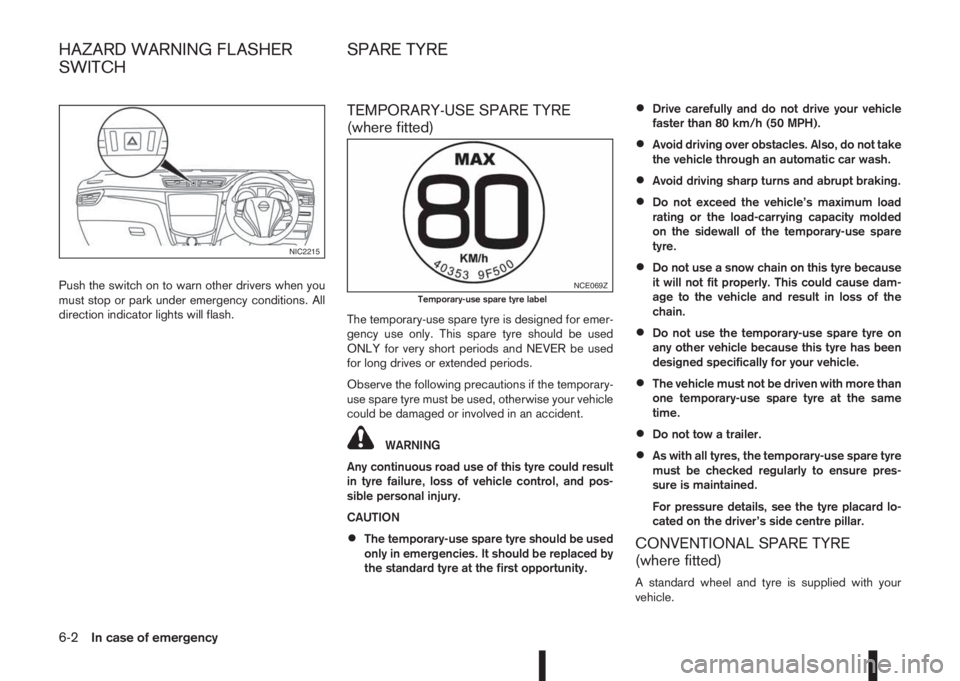
Push the switch on to warn other drivers when you
must stop or park under emergency conditions. All
direction indicator lights will flash.
TEMPORARY-USE SPARE TYRE
(where fitted)
The temporary-use spare tyre is designed for emer-
gency use only. This spare tyre should be used
ONLY for very short periods and NEVER be used
for long drives or extended periods.
Observe the following precautions if the temporary-
use spare tyre must be used, otherwise your vehicle
could be damaged or involved in an accident.
WARNING
Any continuous road use of this tyre could result
in tyre failure, loss of vehicle control, and pos-
sible personal injury.
CAUTION
•The temporary-use spare tyre should be used
only in emergencies. It should be replaced by
the standard tyre at the first opportunity.
•Drive carefully and do not drive your vehicle
faster than 80 km/h (50 MPH).
•Avoid driving over obstacles. Also, do not take
the vehicle through an automatic car wash.
•Avoid driving sharp turns and abrupt braking.
•Do not exceed the vehicle’s maximum load
rating or the load-carrying capacity molded
on the sidewall of the temporary-use spare
tyre.
•Do not use a snow chain on this tyre because
it will not fit properly. This could cause dam-
age to the vehicle and result in loss of the
chain.
•Do not use the temporary-use spare tyre on
any other vehicle because this tyre has been
designed specifically for your vehicle.
•The vehicle must not be driven with more than
one temporary-use spare tyre at the same
time.
•Do not tow a trailer.
•As with all tyres, the temporary-use spare tyre
must be checked regularly to ensure pres-
sure is maintained.
For pressure details, see the tyre placard lo-
cated on the driver’s side centre pillar.
CONVENTIONAL SPARE TYRE
(where fitted)
A standard wheel and tyre is supplied with your
vehicle.
NIC2215
NCE069ZTemporary-use spare tyre label
HAZARD WARNING FLASHER
SWITCHSPARE TYRE
6-2In case of emergency
Page 247 of 338

In case of a flat tyre, follow the instructions as de-
scribed below:
STOPPING THE VEHICLE
WARNING
•Make sure that the parking brake is securely
applied.
•For Manual Transmission (MT) models: Make
sure the shift lever is in the R (Reverse) posi-
tion.
For XTRONIC models: Make sure that the shift
lever is in the P (Park) position.
•Never change tyres when the vehicle is on a
slope, ice or a slippery area. This is hazard-
ous.
•Never change tyres if oncoming traffic is close
to your vehicle. Wait for professional road as-
sistance.
1. Safely move the vehicle off the road, away from
traffic.
2. Switch on the hazard warning flashers.
3. Park on a level surface.
4. Apply the parking brake.
5. Shift the shift lever (MT models) into the R (Re-
verse) position [XTRONIC models, move the shift
lever to the P (Park) position].
6. Turn off the engine.7. Open the bonnet (for details, see “Bonnet
release” in the “3. Pre-driving checks and
adjustments” section) in order to:
•Warn other traffic.
•Signal to professional road assistance that
you require assistance.
8. Have all passengers exit the vehicle and stand in
a safe place, away from traffic and clear of the
vehicle.
CHANGING FLAT TYRE (Models with
spare wheel, where fitted)
Blocking the wheels
WARNING
Make sure to block the appropriate wheel to pre-
vent the vehicle from moving, which may cause
personal injury.
Place suitable blocks
j1 in front of and behind thewheel diagonally opposite the flat tyre
jA to prevent
the vehicle from moving when it is on the jack.
Getting the tools and spare wheel
The spare wheel, jack and tools are located inside
the luggage compartment.
1. Open the back door.
2. Remove the luggage boards and luggage com-
partment floor cover.
3. Remove the retainer by turning it anticlockwise.
4. Remove the jack, tools and spare wheel.
MCE0001DZ
NCE395
FLAT TYRE
In case of emergency6-3
Page 249 of 338

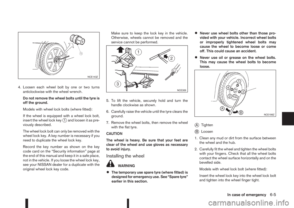
4. Loosen each wheel bolt by one or two turns
anticlockwise with the wheel wrench.
Do not remove the wheel bolts until the tyre is
off the ground.
Models with wheel lock bolts (where fitted):
If the wheel is equipped with a wheel lock bolt,
insert the wheel lock key
j1 and loosen it as pre-
viously described.
The wheel lock bolt can only be removed with the
wheel lock key. A key number is necessary if you
need to duplicate the wheel lock key.
Record the key number as shown on the key
code card on the “Security information” page at
the end of this manual and keep it in a safe place,
not in the vehicle. If you loose the wheel lock key,
see your NISSAN dealer for a duplicate with the
original wheel lock key code.Make sure to keep the lock key in the vehicle.
Otherwise, wheels cannot be removed and the
service cannot be performed.
5. To lift the vehicle, securely hold and turn the
handle clockwise as shown.
6. Carefully raise the vehicle until the tyre clears the
ground.
7. Remove the wheel bolts, then remove the wheel
with the flat tyre.
CAUTION
The wheel is heavy. Be sure that your feet are
clear of the wheel and use gloves as necessary
to avoid injury.
Installing the wheel
WARNING
•The temporary use spare tyre (where fitted) is
designed for emergency use. See “Spare tyre”
earlier in this section.
•Never use wheel bolts other than those pro-
vided with your vehicle. Incorrect wheel bolts
or improperly tightened wheel bolts may
cause the wheel to become loose or come
off. This could cause an accident.
•Never use oil or grease on the wheel bolts.
This may cause the wheel bolts to become
loose.
jATighten
jBLoosen
1. Clean any mud or dirt from the surface between
the wheel and the hub.
2. Carefully fit the wheel and tighten the wheel bolts
with your fingers. Check that all the wheel bolts
contact the wheel surface horizontally and on the
bevelled side.
Models with wheel lock bolt (where fitted):
Insert the wheel lock key into the wheel lock bolt
and tighten into the wheel finger tight.
NCE143Z
NCE309
NCE198Z
In case of emergency6-5
Page 251 of 338

TYRE PRESSURE MONITORING
SYSTEM (TPMS) (where fitted)
j
ATyre valve with sensor
WARNING
•If the TPMS indicator light illuminates while
driving:
– avoid sudden steering manoeuvres
– avoid abrupt braking
– reduce vehicle speed
– pull off the road to a safe location
– stop the vehicle as soon as possible
•Driving with under-inflated tyres may perma-
nently damage the tyres and increase the like-
lihood of tyre failure. Serious vehicle damage
could occur which may lead to an accident
and could result in serious personal injury.
•Check the tyre pressure for all four tyres. Ad-
just the tyre pressure to the recommended
COLD tyre pressure shown on the tyre plac-
ard to turn the TPMS indicator light “OFF”. In
case of a flat tyre, replace it with a spare tyre
as soon as possible.
•When a spare tyre is mounted or a wheel is
replaced, the TPMS will not function and the
TPMS indicator light will flash for approxi-
mately 1 minute. The light will remain on after
1 minute. Be sure to follow all instructions for
wheel replacement and make sure the TPMS
system is mounted correctly.
•Replacing tyres with those not originally speci-
fied by NISSAN could affect the proper opera-
tion of the TPMS.
•The Genuine NISSAN Emergency Tyre Repair
Sealant can be used for temporarily repairing
a tyre. Do not inject any other tyre liquid or
aerosol tyre sealant into the tyres, as this may
cause a malfunction of the tyre pressure sen-
sors.
•NISSAN recommends using only Genuine
NISSAN Emergency Tyre Sealant provided
with your vehicle. Other tyre sealants may
damage the valve stem seal which can cause
the tyre to lose air pressure. Visit a NISSAN
dealer or qualified workshop as soon as pos-
sible after using tyre repair sealant (for mod-
els equipped with the emergency tyre punc-
ture repair kit).CAUTION
•The TPMS may not function properly when the
wheels are equipped with tyre chains or the
wheels are buried in snow.
•Do not place metalised film or any metal parts
(antenna, etc.) on the windows. This may
cause poor reception of the signals from the
tyre pressure sensors, and the TPMS will not
function properly.
Some devices and transmitters may tempo-
rarily interfere with the operation of the TPMS
and cause the TPMS indicator light to illumi-
nate. Some examples are:
– Facilities or electric devices using similar
radio frequencies are near the vehicle.
– If a transmitter set to similar frequencies is
being used in or near the vehicle.
– If a computer (or similar equipment) or a
DC/AC converter is being used in or near
the vehicle.
•When inflating the tyres and checking the tyre
pressure, never bend the valves.
•Special aluminium valves are fitted to mount
the TPMS sensors on the wheels. The TPMS
sensor is fixed at the wheels by a nut. The nut
needs to be correctly fitted at a torque setting
of 7.5 ± 0.5 Nm. If the TPMS sensor is tight-
ened exceeding the limit, there is a possibility
NCE373
In case of emergency6-7
Page 252 of 338

the sensor grommet will be damaged. If the
sensor is tightened under the limit, there is a
possibility to cause an air leak.
•Use Genuine NISSAN valve caps that comply
with the factory-fitted valve cap specifications.
•Do not use metal valve caps.
•Fit the valve caps properly. Without the valve
caps the valve and tyre pressure monitor sen-
sors could be damaged.
•Do not damage the valves and sensors when
storing the wheels or fitting different tyres.
•Replace the sensor grommet and washer dur-
ing a tyre change. Once they have been re-
moved, the sensor grommet and washer can-
not be reused and must be replaced. The
TPMS sensors can be used again.
The Tyre Pressure Monitoring System (TPMS) moni-
tors the tyre pressure of the four wheels except the
spare wheel. When the TPMS indicator light comes
on together with the TPMS tyre location indicator
light (in the meter panel), one or more of the tyres is
significantly under-inflated. If the vehicle is being
driven with low tyre pressure, the TPMS will activate
and TPMS indicator light together with the TPMS
tyre location indicator light remains on. This system
will deactivate only when tyre pressure is corrected
and the vehicle is driven at speeds above 25 km/h
(16 MPH).
For more details about the TPMS, see “Tyre Pres-
sure Monitoring System (TPMS)” in the “5. Starting
and driving” section.
REPAIRING FLAT TYRE (Models with
emergency tyre puncture repair kit)
The emergency tyre puncture repair kit is supplied
with the vehicle instead of a spare tyre. This repair
kit must be used for temporarily fixing a minor tyre
puncture. After using the repair kit, see a NISSAN
dealer or qualified workshop as soon as possible for
tyre inspection and repair/replacement.
CAUTION
Do not use the emergency tyre puncture repair
kit under the following conditions. Contact a
NISSAN dealer or qualified workshop or profes-
sional road assistance.
•when the sealant has passed its expiration
date (shown on the label attached to the
bottle)
•when the cut or the puncture is approximately
4 mm (0.16 in) or longer
•when the side of the tyre is damaged
•when the vehicle has been driven with a con-
siderable loss of air from the tyre
•when the tyre is completely displaced inside
or outside the rim
•when the tyre rim is damaged
•when two or more tyres are flat
Getting emergency tyre puncture repair
kit
Take the emergency tyre puncture repair kit out of
the boot. The repair kit consists of the following
items:
j1Tyre sealant bottle
j2Air compressor
j3Speed restriction sticker
NOTE
For models with the emergency tyre puncture
repair kit, a spare tyre, jack and rod are not
equipped as standard. These parts are dealer
options. Contact a NISSAN dealer or qualified
workshop about obtaining these parts. See “Re-
moving the wheel” earlier in this section for us-
age of jacking tools and tyre replacement.
NCE371
6-8In case of emergency
Page 260 of 338

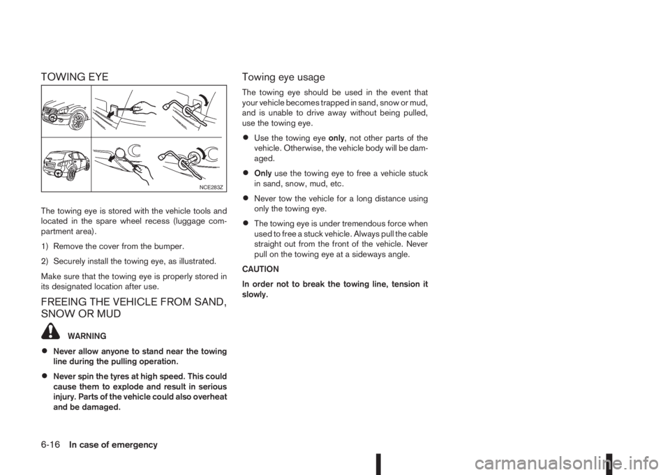
TOWING EYE
The towing eye is stored with the vehicle tools and
located in the spare wheel recess (luggage com-
partment area).
1) Remove the cover from the bumper.
2) Securely install the towing eye, as illustrated.
Make sure that the towing eye is properly stored in
its designated location after use.
FREEING THE VEHICLE FROM SAND,
SNOW OR MUD
WARNING
•Never allow anyone to stand near the towing
line during the pulling operation.
•Never spin the tyres at high speed. This could
cause them to explode and result in serious
injury. Parts of the vehicle could also overheat
and be damaged.
Towing eye usage
The towing eye should be used in the event that
your vehicle becomes trapped in sand, snow or mud,
and is unable to drive away without being pulled,
use the towing eye.
•Use the towing eyeonly, not other parts of the
vehicle. Otherwise, the vehicle body will be dam-
aged.
•Onlyuse the towing eye to free a vehicle stuck
in sand, snow, mud, etc.
•Never tow the vehicle for a long distance using
only the towing eye.
•The towing eye is under tremendous force when
used to free a stuck vehicle. Always pull the cable
straight out from the front of the vehicle. Never
pull on the towing eye at a sideways angle.
CAUTION
In order not to break the towing line, tension it
slowly.
NCE283Z
6-16In case of emergency