Page 294 of 338

•Be careful not to damage the connector sup-
port bracket when disconnecting the connec-
tor.
If any electrical equipment does not operate, check
for an open fuse.
The fuse box is located in the lower part of the
instrument panel at the driver’s side.
The affected circuits
j2 are shown on the inside of
the fuse box lid.
1. Make sure the ignition switch and the headlight
switch are in the “OFF” position.
2. Open the fuse box lid.
3. Locate and remove the fuse with the fuse puller
j1 (where fitted).
NOTE
The fuse puller is stored in the fuse box.
4. If the fuse is open
jA , replace it with a new fusejB.
5. Close the fuse box lid.
NOTE
If the new fuse opens again, after installing,
have the electrical system checked and re-
paired by a NISSAN dealer or qualified work-
shop.
Extended storage fuse switch
To reduce battery drain, the extended storage fuse
switchj3 comes from the factory switched off. Prior
to delivery of your vehicle, the switch is pushed in
(switched on) and should always remain on.
If any electrical equipment does not operate, re-
move the extended storage fuse switch and check
for an open fuse.
NOTE
If the extended storage fuse switch malfunctions
or if the fuse is open, it is not necessary to re-
place the switch. In this case, remove the ex-
tended storage fuse switch and replace it with a
new fuse of the same rating.
How to remove the extended storage fuse
switch:
1. To remove the extended storage fuse switch, be
sure the ignition switch is in the “OFF” or LOCK
position.
2. Be sure the headlight switch is in the “OFF”
position.
3. Remove the fuse box cover.
4. Pinch the locking tabs found on each side of the
extended storage fuse switch
j3.
5. Pull the extended storage fuse switch straight
out from the fuse box.
ENGINE COMPARTMENT
CAUTION
Never use a fuse of higher or lower amperage
rating than that specified on the fuse box cover.
If any electrical equipment does not operate, check
for an open fuse.
NDI1089
8-26Maintenance and do-it-yourself
Page 295 of 338
1. Make sure the ignition switch and the headlight
switch are in the “OFF” position.
2. Open the bonnet. For details, see “Bonnet
release” in the “3. Pre-driving checks and
adjustments” section.
3. Remove the air duct, see “Air duct removal” ear-
lier in this section.
4. Remove the fusible link covers.
5. Locate the fuse that needs to be replaced.
6. Remove the fuse with the fuse puller (where fit-
ted). The fuse puller is located in the fuse box of
the passenger compartment.
7. If the fuse is open
jA , replace it with a new fusejB.
8. Install the fusible link covers.
9. Install the air duct in the reverse order of re-
moval.
10. Close the bonnet.
NOTE
If the new fuse opens again, after installing,
have the electrical system checked and re-
paired by a NISSAN dealer or qualified work-
shop.
NDI1493
LIGHTS
Maintenance and do-it-yourself8-27
Page 296 of 338

HEADLIGHTS
LED headlight (where fitted)
The LED headlight is a projector style which uses a
LED module without serviceable parts.
CAUTION
•To prevent an electric shock, never attempt to
modify or disassemble the LED headlights as-
sembly.
•If replacement is required, contact a NISSAN
dealer or qualified workshop.
Replacing the halogen headlight bulb
CAUTION
•High pressure halogen gas is sealed inside
the halogen bulb. The bulb may break if the
glass envelope is scratched or the bulb is
dropped.
•When handling the bulb, DO NOT TOUCH THE
GLASS ENVELOPE.
•Use the same number type and wattage as
originally installed.
•Aiming is usually not necessary after replac-
ing the bulb. When aiming adjustment is nec-
essary, contact a NISSAN dealer or qualified
workshop.
•Do not leave the bulb out of the headlight
reflector for a long period of time as dust,moisture or smoke may enter the headlight
body and affect the performance of the head-
light.
The headlight is a semi-sealed beam type which
uses a replaceable headlight (halogen) bulb. A bulb
can be replaced from inside the engine compart-
ment without removing the headlight assembly.
Contact a NISSAN dealer or qualified workshop, if
you need assistance for bulb replacement.
High beam bulb replacement:
1. Open the bonnet. For details, see “Bonnet
release” in the “3. Pre-driving checks and
adjustments” section.
2. Disconnect the negative (—) battery cable.
3. When the broken bulb is located in the headlight
assembly under the air duct, carefully remove the
air duct, see “Air duct removal” earlier in this
section.
4. Remove the connector from the back of the cover
assembly
j1.
5. Turn the cover assembly 1/4 of a turn in the anti
clockwise direction and remove the cover by dis-
connecting the internal connector
j2.
6. Push and turn the retaining pin to loosen it
j3.
7. Remove the headlight bulb. Do not shake or ro-
tate the bulb when removing it.
8. Install the new bulb in the reverse order of re-
moval.9. Re-install the covers internal connector on the
back of the bulb.
10. Re-install the cover by turning the cover assem-
bly 1/4 of a turn in the clockwise direction.
11. Re-install the connector on the back of the cover
assembly.
12. Where removed (step 3.), re-install the air duct,
bolt and clips in the reverse order of removal.
13. Reconnect the negative (—) battery cable and
close the bonnet.
Low beam bulb replacement:
1. Open the bonnet. For details, see “Bonnet
release” in the “3. Pre-driving checks and
adjustments” section.
2. Disconnect the negative (—) battery cable.
3. When the broken bulb is located in the headlight
assembly under the air duct, carefully remove the
air duct, see “Air duct removal” earlier in this
section.
4. Remove the connector from the back of the bulb
assembly
j4.
5. Turn the bulb assembly 1/8 of a turn in the anti
clockwise direction and remove the headlight
bulb
j5.
6. Install the new bulb in the headlight body by turn-
ing it clockwise until it is securely sealed within
the headlight body.
7. Re-install the connector on the back of the bulb
assembly.
8-28Maintenance and do-it-yourself
Page 297 of 338

8. Where removed (step 3.), re-install the air duct,
bolt and clips in the reverse order of removal.
9. Reconnect the negative (—) battery cable and
close the bonnet.
NOTE
Fog may temporarily form inside the lens of the
exterior lights in the rain or in a car wash. The fog
is caused by a temperature difference between
the inside and the outside of the lens. This is not
a malfunction. If large droplets can be seen, then
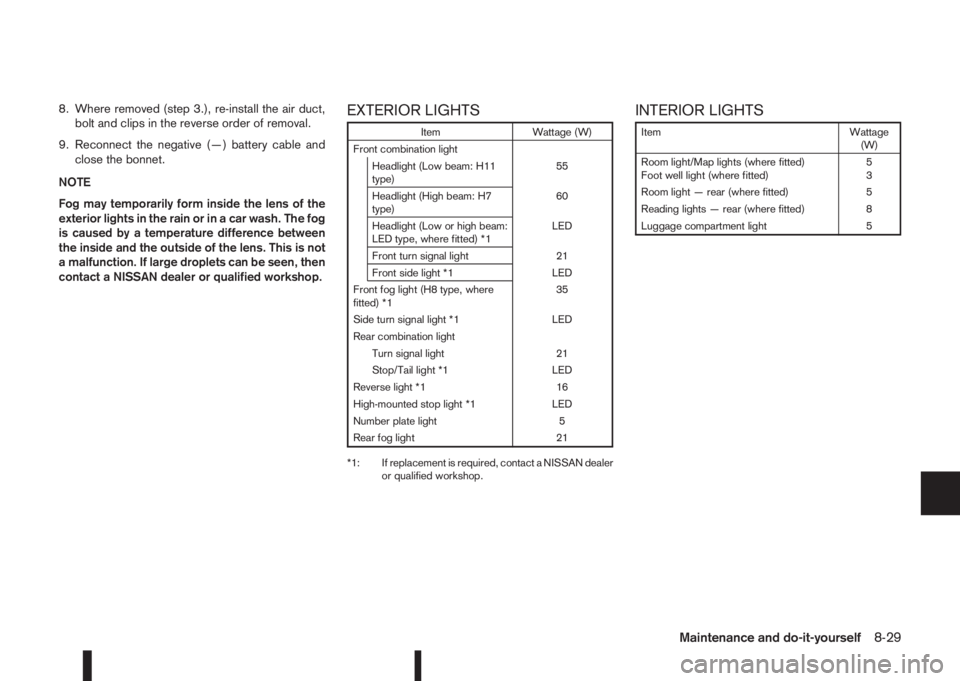
contact a NISSAN dealer or qualified workshop.EXTERIOR LIGHTS
Item Wattage (W)
Front combination light
Headlight (Low beam: H11
type)55
Headlight (High beam: H7
type)60
Headlight (Low or high beam:
LED type, where fitted) *1LED
Front turn signal light 21
Front side light *1 LED
Front fog light (H8 type, where
fitted) *135
Side turn signal light *1 LED
Rear combination light
Turn signal light 21
Stop/Tail light *1 LED
Reverse light *1 16
High-mounted stop light *1 LED
Number plate light 5
Rear fog light 21
*1: If replacement is required, contact a NISSAN dealer
or qualified workshop.
INTERIOR LIGHTS
Item Wattage
(W)
Room light/Map lights (where fitted)
Foot well light (where fitted)5
3
Room light — rear (where fitted) 5
Reading lights — rear (where fitted) 8
Luggage compartment light 5
Maintenance and do-it-yourself8-29
Page 298 of 338
LIGHT LOCATIONS
j
1Side turn signal light
j2Room light/Map lights (where fitted)
j3Low beam headlight
j4High beam headlight
j5Front side light
j6Front turn signal light
j7Front fog light (where fitted)
j8Footwell light (where fitted)
j9Room light (where fitted)
j10High mounted stop light
j11Number plate light
j12Rear fog light (where fitted)
j13Reverse light
j14Stop light
j15Tail light
Replacing procedures
All other lights are either type A, B, C or D.
When replacing a bulb, first remove the lens
and/or cover.
mREMOVE
mINSTALL
NDI1453Light locationsNDI707
8-30Maintenance and do-it-yourself
Page 299 of 338
NDI1437Front turn signal light
NDI740ZRoom light / Map lights (where fitted)
NDI739ZRoom light — rear (where fitted)
NDI933Reading light — rear (where fitted)
Maintenance and do-it-yourself8-31
Page 300 of 338
NDI1097Foot well light (where fitted)NDI1457Luggage compartment lightNDI1458Number plate light
8-32Maintenance and do-it-yourself
Page 301 of 338

In case of a flat tyre, see “Flat tyre” in the “6. In case
of emergency” section.
TYRE INFLATION PRESSURE
Periodically check the tyre pressure (including the
spare tyre). An incorrect tyre pressure may ad-
versely affect tyre life and vehicle handling. After
adjusting the tyre pressure, perform a TPMS tem-
perature calibration (see “TPMS temperature
calibration” in the “5. Starting and driving” section).
NOTE
Incorrectly inflated tyres can also lead to poor
steering ability and make the driver suspect a
steering problem: keep the vehicle’s tyres in-
flated to the correct pressure at all times.
The tyre pressure should be checked when tyres
are COLD. Tyres are considered COLD after the
vehicle has been parked for three or more hours, or
driven less than 1.6 km (1 mile). COLD tyre pres-
sures are shown on the tyre placard affixed to the
driver’s side centre pillar.
Insufficient pressure can lead to an overheating of
the tyre and subsequent internal damage. At high
speeds, this could result in tread separation and
even bursting of the tyre.
TYPES OF TYRES
CAUTION
•When changing or replacing tyres, be sure all
four tyres are of the same type (i.e., summer,
all season or snow) and construction.
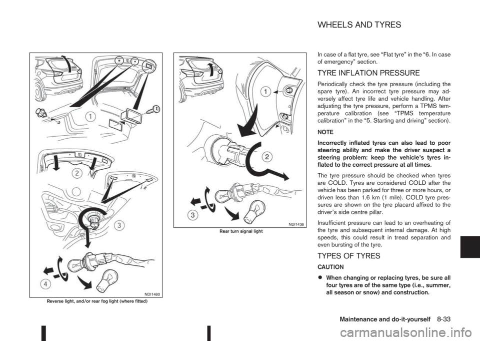
NDI1480Reverse light, and/or rear fog light (where fitted)
NDI1438Rear turn signal light
WHEELS AND TYRES
Maintenance and do-it-yourself8-33