Page 25 of 50
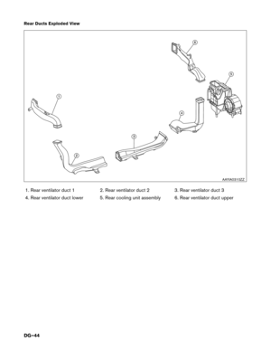
Alternate Procedure 1 (Remove Fuses)
NOTE:Before removing any fuses, if necessary, lower the windows, adjust the steering column,
adjust the seats, unlock the doors, etc. Once fuses are removed, power controls will notoperate.
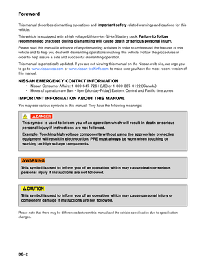
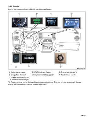
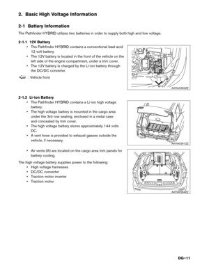
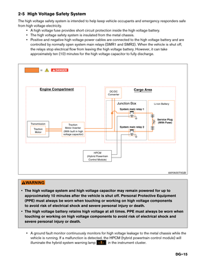
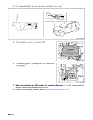
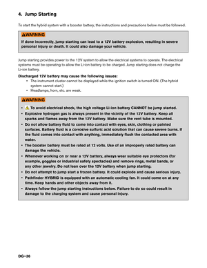
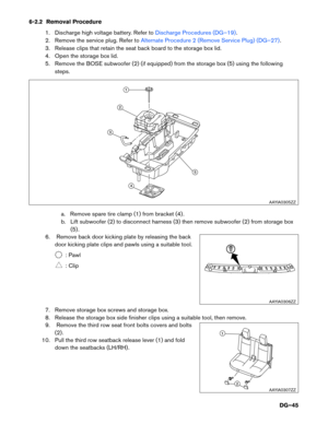
1. Pull release handle (1) and pull up release lever (2) to open the hood.
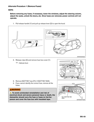
2. Release clips (A) and remove fuse box cover (1) .
: Vehicle front
3. Remove IGCT RLY fuse (F/L V IGCT RLY 50A) .
4. If you cannot identify the correct fuse, remove all the fuses.
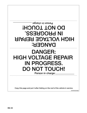
To avoid unintended reinstallation and risk of
electrical shock and severe personal injury or death, the
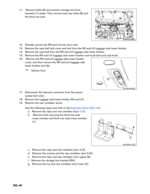
dismantler should carry the fuse or fuses on his/her
person and cover the fuse box with insulated tape.
1
2
AAYIA0325ZZ
1
A
AAYIA0326ZZ
F/L V IGCT RLY 50A (Red)
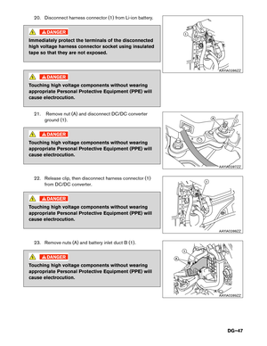
AAYIA0071GB
DG–25
Page 26 of 50
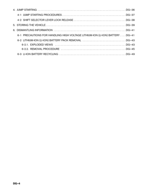
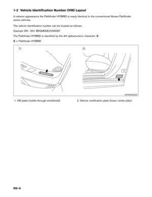
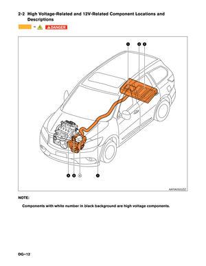
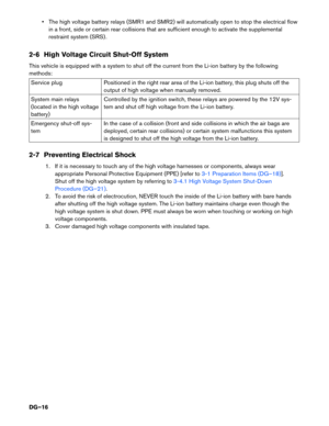
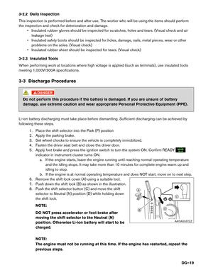
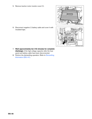
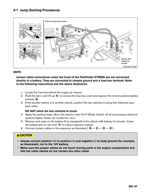
5. Remove traction motor inverter cover (1) .
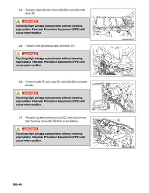
6. Disconnect negative (-) battery cable and cover it withinsulated tape.
7. Wait approximately ten (10) minutes for complete
discharge of the high voltage capacitor after the fuse
panel and battery cable have been disconnected.
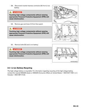
8. Perform the dismantling operation. Refer to
Dismantling
Information (DG–41)
.
1
AAYIA0273ZZ
AAYIA0274ZZ
DG–26
Page 27 of 50

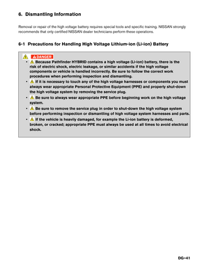
•Do not remove the service plug without always wearing appropriate Personal
Protective Equipment (PPE) to help protect the dismantler from serious injury")
Alternate Procedure 2 (Remove Service Plug)
•Do not remove the service plug without always wearing appropriate Personal
Protective Equipment (PPE) to help protect the dismantler from serious injury or death
by electrical shock.
•
Immediately cover the service plug socket with insulated tape. The Li-ion battery
retains high voltage power even when the service plug is removed. To avoid electric
shock, NEVER touch the terminals inside the socket.
To avoid unintended reinstallation and risk of electrical shock and severe personal injury
or death, the dismantler should carry the service plug on his/her person while work is in progress.
NOTE: Before disconnecting the 12V battery terminal, if necessary, lower the windows, adjust the
steering column, adjust the seats, unlock the doors, etc. Once 12V battery is disconnected,
power controls will not operate.
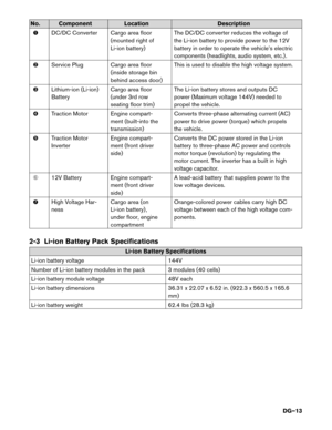
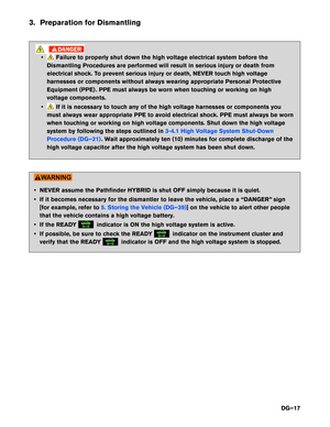
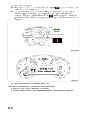
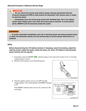
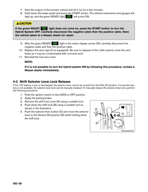
1. If possible, check the READY
indicator status in the instrument cluster. If it is on, the high
voltage system is active.
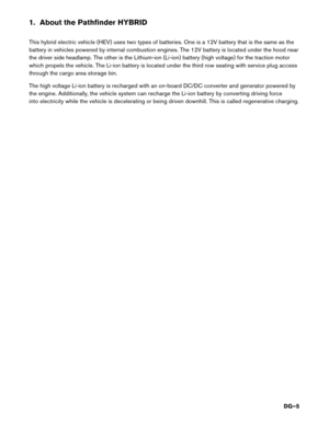
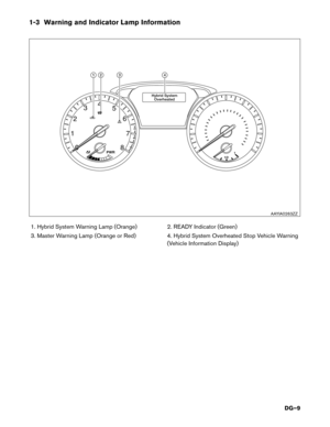
2. Place the shift selector in the Park (P) position.
3. Push the ignition switch once to turn OFF the high voltage system. Then verify whether the READY indicator
is off.
If the READY indicator does not turn off, continue to the
next steps.
AAYIA0333ZZ
ACC
LOCK
(OFF)
ON
AAYIA0321ZZ
DG–27
Page 28 of 50
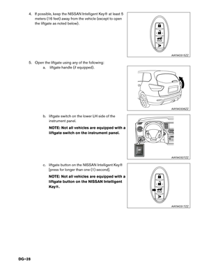
4. If possible, keep the NISSAN Intelligent Key® at least 5meters (16 feet) away from the vehicle (except to open
the liftgate as noted below) .
5. Open the liftgate using any of the following: a. liftgate handle (if equipped) .
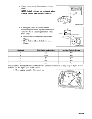
b. liftgate switch on the lower LH side of theinstrument panel.
NOTE: Not all vehicles are equipped with a
liftgate switch on the instrument panel.
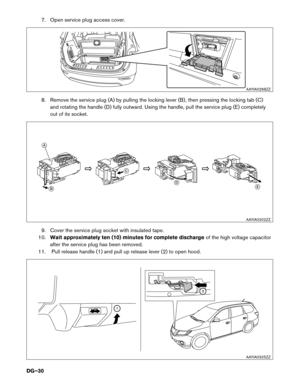
c. liftgate button on the NISSAN Intelligent Key® [press for longer than one (1) second].
NOTE: Not all vehicles are equipped with a
liftgate button on the NISSAN IntelligentKey®.
HOLD
AAYIA0315ZZ
AAYIA0336ZZ
AAYIA0327ZZ
HOLD
AAYIA0317ZZ
DG–28
Page 29 of 50
d. liftgate opener switch (located above licenseplate)*.
NOTE: Not all vehicles are equipped with a
liftgate opener switch in this location.
e. If the liftgate cannot be opened with the instrument panel switch, liftgate opener switch,
or key fob due to a discharged battery, follow
these steps:
• Remove the cover (A) on the inside of theliftgate.
• Move the lever (B) as illustrated to open liftgate.
Method Shift Selector Position Ignition Switch Status
a Any Any
b P or N Any c P OFF
d* Any Any e Any Any
* You must have the NISSAN Intelligent Key® within approximately 1 meter (3 feet) range of liftgate opener
switch to use the liftgate open switch function. 6. Open luggage board by lifting handle (A) .
A
AAYIA0328ZZ
A
B
AAYIA0316ZZ
A
AAYIA0267ZZ
DG–29
Page 30 of 50
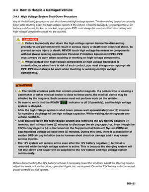
7. Open service plug access cover.
8. Remove the service plug (A) by pulling the locking lever (B) , then pressing the locking tab (C)and rotating the handle (D) fully outward. Using the handle, pull the service plug (E) completely
out of its socket.
9. Cover the service plug socket with insulated tape.
10. Wait approximately ten (10) minutes for complete discharge of the high voltage capacitor
after the service plug has been removed.
11. Pull release handle (1) and pull up release lever (2) to open hood.
AAYIA0268ZZ
A
B
C
DE
AAYIA0202ZZ
1
2
AAYIA0325ZZ
DG–30
Page 31 of 50
 .
13. Disconnect negative (-) battery cable and cover it withinsulated tape.
14. Perform the dismantling operation. Refer to
Dismantling Information (DG�")
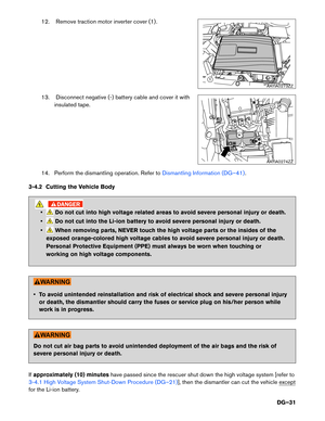
12. Remove traction motor inverter cover (1) .
13. Disconnect negative (-) battery cable and cover it withinsulated tape.
14. Perform the dismantling operation. Refer to
Dismantling Information (DG–41).
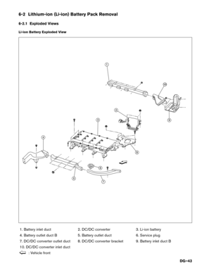
3-4.2 Cutting the Vehicle Body
•Do not cut into high voltage related areas to avoid severe personal injury or death.
•
Do not cut into the Li-ion battery to avoid severe personal injury or death.
•
When removing parts, NEVER touch the high voltage parts or the insides of the
exposed orange-colored high voltage cables to avoid severe personal injury or death.
Personal Protective Equipment (PPE) must always be worn when touching or
working on high voltage components.
• To avoid unintended reinstallation and risk of electrical shock and severe personal injury or death, the dismantler should carry the fuses or service plug on his/her person while
work is in progress.
Do not cut air bag parts to avoid unintended deployment of the air bags and the risk of
severe personal injury or death.
If approximately (10) minutes have passed since the rescuer shut down the high voltage system [refer to
3-4.1 High Voltage System Shut-Down Procedure (DG–21)], then the dismantler can cut the vehicle except
for the Li-ion battery.
1
AAYIA0273ZZ
AAYIA0274ZZ
DG–31
Page 32 of 50

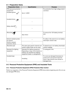
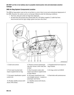
DO NOT cut the Li-ion battery due to possible electrocution risk and electrolyte solution leakage.
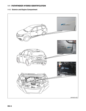
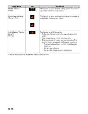
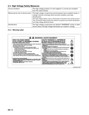
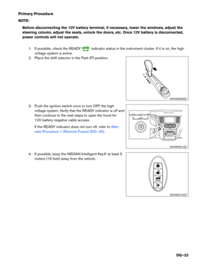
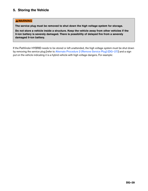
SRS Air Bag System Components Location
The SRS air bag system must not be cut as there is a risk of short circuit and unintentional deployment of
the SRS. However, the vehicle can be cut (except inflators) under the following conditions:• The front, side and curtain air bags have deployed.
• At least three (3) minutes have passed after the 12V battery negative (-) cable has been
disconnected and the high voltage system has been shut down.
1. Crash zone sensor 2. Pressure sensors (passenger side door shown; driver side door similar)3. Supplemental front-impact air
bag modules
4. Front seat-mounted side-
impact supplemental air bag 5. Roof-mounted curtain side-
impact and rollover supplemental
air bag inflators6. Air bag control unit (ACU)
7. Occupant classification system
control unit 8. Occupant classification sen-
sors (weight sensors – located on
passenger seat frame)9. Seat belts with pretensioners
10. B-pillar satellite sensors (LH
shown, RH similar) 11. Satellite sensors (LH shown,
RH similar)
4
891011
53
21
67AAYIA0324ZZ
DG–32


NOTE:Before removing any fuses, if necessary, lower the windows, adjust the steering column,
adjust the seats, unlock the doors, etc. Once fuses are removed, pow")
 .
6. Disconnect negative (-) battery cable and cover it withinsulated tape.
7. Wait approximately ten (10) minutes for complete
discharge of the high volta")
 away from the vehicle (except to open
the liftgate as noted below) .
5. Open the liftgate using any of the following: a. l")
*.
NOTE: Not all vehicles are equipped with a
liftgate opener switch in this location.
e. If the liftgate cannot be opened with the instrument p")
 by pulling the locking lever (B) , then pressing the locking tab (C)and rotating the handle (D) fully outward. Using the handle, pull")