2014 NISSAN LEAF Park position
[x] Cancel search: Park positionPage 3 of 39
Table of Contents
FOREWORD
. . . . . . . . . . . . . . . . . . . . . . . . . . . . . . . . . . . . . . . . . . . . . . . . . . . . . . . . . . . . . . . . . . RAG–2
NISSAN EMERGENCY CONTACT INFORMATION . . . . . . . . . . . . . . . . . . . . . . . . . . . . . . . . . . RAG–2
IMPORTANT INFORMATION ABOUT THIS MANUAL . . . . . . . . . . . . . . . . . . . . . . . . . . . . . . . . RAG–2
1. ABOUT THE NISSAN LEAF® . . . . . . . . . . . . . . . . . . . . . . . . . . . . . . . . . . . . . . . . . . . . . . . . . . . RAG–5 1-1 LEAF IDENTIFICATION . . . . . . . . . . . . . . . . . . . . . . . . . . . . . . . . . . . . . . . . . . . . . . . . . . . . RAG–6 1-1.1. EXTERIOR . . . . . . . . . . . . . . . . . . . . . . . . . . . . . . . . . . . . . . . . . . . . . . . . . . . . . . . . RAG–6
1-1.2. INTERIOR COMPONENT LOCATION . . . . . . . . . . . . . . . . . . . . . . . . . . . . . . . . . . . RAG–7
1-1.3. VEHICLE IDENTIFICATION NUMBER (VIN) LAYOUT . . . . . . . . . . . . . . . . . . . . . . . RAG–8
1-1.4. WARNING AND INDICATOR LAMP INFORMATION . . . . . . . . . . . . . . . . . . . . . . . . RAG–8
2. BASIC HIGH VOLTAGE INFORMATION . . . . . . . . . . . . . . . . . . . . . . . . . . . . . . . . . . . . . . . . . . . RAG–9 2-1 HIGH VOLTAGE-RELATED AND 12V-RELATED COMPONENT LOCATIONS AND DESCRIPTIONS . . . . . . . . . . . . . . . . . . . . . . . . . . . . . . . . . . . . . . . . . . . . . . . . . . . . . . . . . RAG–9
2-1.1. LI-ION BATTERY PACK SPECIFICATIONS . . . . . . . . . . . . . . . . . . . . . . . . . . . . . . RAG–11
2-2 HIGH VOLTAGE SAFETY MEASURES . . . . . . . . . . . . . . . . . . . . . . . . . . . . . . . . . . . . . . . RAG–11 2-2.1. WARNING LABEL . . . . . . . . . . . . . . . . . . . . . . . . . . . . . . . . . . . . . . . . . . . . . . . . . RAG–11
3. ROADSIDE ASSISTANCE RESPONSE STEPS . . . . . . . . . . . . . . . . . . . . . . . . . . . . . . . . . . . . RAG–12 3-1 INDICATIONS THE HIGH VOLTAGE SYSTEM IS ON . . . . . . . . . . . . . . . . . . . . . . . . . . . RAG–12
3-2 VEHICLE IMMOBILIZATION AND STABILIZATION . . . . . . . . . . . . . . . . . . . . . . . . . . . . . . RAG–13
3-3 TURNING OFF THE POWER SWITCH . . . . . . . . . . . . . . . . . . . . . . . . . . . . . . . . . . . . . . RAG–14
3-4 WATER SUBMERSION . . . . . . . . . . . . . . . . . . . . . . . . . . . . . . . . . . . . . . . . . . . . . . . . . . . RAG–14
3-5 VEHICLE FIRE . . . . . . . . . . . . . . . . . . . . . . . . . . . . . . . . . . . . . . . . . . . . . . . . . . . . . . . . . . RAG–15
3-6 LI-ION BATTERY DAMAGE AND FLUID LEAKS . . . . . . . . . . . . . . . . . . . . . . . . . . . . . . . . RAG–16
4. ROADSIDE ASSISTANCE . . . . . . . . . . . . . . . . . . . . . . . . . . . . . . . . . . . . . . . . . . . . . . . . . . . . . RAG–17 4-1 JUMP STARTING . . . . . . . . . . . . . . . . . . . . . . . . . . . . . . . . . . . . . . . . . . . . . . . . . . . . . . . RAG–174-1.1. JUMP STARTING PROCEDURES . . . . . . . . . . . . . . . . . . . . . . . . . . . . . . . . . . . . . RAG–18
4-2 P (PARK) POSITION RELEASE PROCEDURE . . . . . . . . . . . . . . . . . . . . . . . . . . . . . . . . . RAG–19 4-2.1. RESET PROCEDURE . . . . . . . . . . . . . . . . . . . . . . . . . . . . . . . . . . . . . . . . . . . . . . RAG–21
4-3 TOWING . . . . . . . . . . . . . . . . . . . . . . . . . . . . . . . . . . . . . . . . . . . . . . . . . . . . . . . . . . . . . . RAG–22 4-3.1. VEHICLE SPECIFICATIONS . . . . . . . . . . . . . . . . . . . . . . . . . . . . . . . . . . . . . . . . . RAG–22
4-3.2. TOWING GUIDELINES . . . . . . . . . . . . . . . . . . . . . . . . . . . . . . . . . . . . . . . . . . . . . RAG–22
4-3.3. USE OF VEHICLE EQUIPPED HOOKS FOR RECOVERY OPERATIONS . . . . . . RAG–24
4-4 STORING THE VEHICLE . . . . . . . . . . . . . . . . . . . . . . . . . . . . . . . . . . . . . . . . . . . . . . . . . RAG–26
4-5 JACKING UP THE VEHICLE AND CHANGING A TIRE . . . . . . . . . . . . . . . . . . . . . . . . . . RAG–26
4-6 TOOLS INSTALLED IN THE VEHICLE . . . . . . . . . . . . . . . . . . . . . . . . . . . . . . . . . . . . . . . RAG–27
RAG–3
Page 18 of 39
4-1.1 Jump Starting Procedures
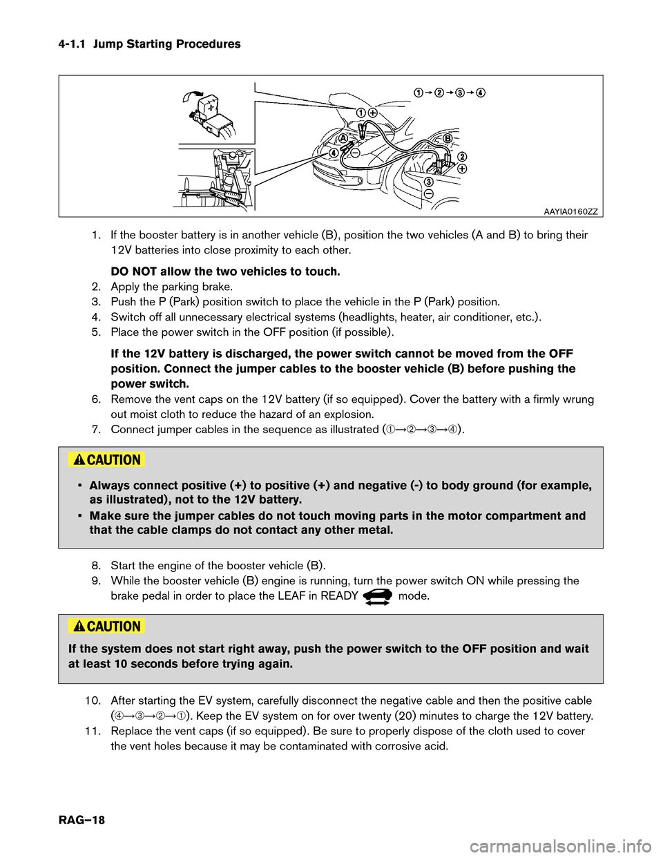
1. If the booster battery is in another vehicle (B) , position the two vehicles (A and B) to bring their
12V batteries into close proximity to each other.
DO NOT allow the two vehicles to touch.
2. Apply the parking brake.
3. Push the P (Park) position switch to place the vehicle in the P (Park) position.
4. Switch off all unnecessary electrical systems (headlights, heater, air conditioner, etc.) .
5. Place the power switch in the OFF position (if possible) .
If the 12V battery is discharged, the power switch cannot be moved from the OFF
position. Connect the jumper cables to the booster vehicle (B) before pushing the
power switch.
6. Remove the vent caps on the 12V battery (if so equipped) . Cover the battery with a firmly wrung out moist cloth to reduce the hazard of an explosion.
7. Connect jumper cables in the sequence as illustrated (�������) . • Always connect positive (+) to positive (+) and negative (-) to body ground (for example,
as
illustrated) , not to the 12V battery.
• Make sure the jumper cables do not touch moving parts in the motor compartment and that the cable clamps do not contact any other metal.
8. Start the engine of the booster vehicle (B) .
9. While the booster vehicle (B) engine is running, turn the power switch ON while pressing the brake pedal in order to place the LEAF in READY mode.
If the system does not start right away, push the power switch to the OFF position and wait
at
least 10 seconds before trying again.
10. After starting the EV system, carefully disconnect the negative cable and then the positive cable (�������) . Keep the EV system on for over twenty (20) minutes to charge the 12V battery.
11. Replace the vent caps (if so equipped) . Be sure to properly dispose of the cloth used to cover the vent holes because it may be contaminated with corrosive acid. AAYIA0160ZZ
RAG–18
Page 19 of 39
12. If necessary, connect the vehicle to a charging station or EVSE (Electric Vehicle Supply
Equipment) to charge the Li-ion battery. The vehicle cannot be driven unless the Li-ion battery is
charged.
NOTE:
If it is not possible to turn the LEAF system ON by following this procedure, contact a
NISSAN certified LEAF dealer immediately.
4-2 P (Park) Position Release Procedure
If you need to release the vehicle from the P (Park) position, proceed as follows. When power switch is
turned OFF or 12V battery is low, LEAF automatically shifts to P position.
NOTE: This procedure requires two (2) people.
1. To start the EV system with a booster battery, refer to 4-1 Jump Starting (RAG–17).
2.
Turn power switch ON by pushing the power switch 2 times without pressing brake pedal.
3. Confirm parking brake is applied.
4. Close all doors and press and hold the brake pedal.
5. Place the selector lever in the N (Neutral) position.
6. Remove the following 2 fuses:
• F/L 40A PBW MTR (under hood fuse and relay box)
• METER 1 10A (in the cabin fuse box)
RAG–19
Page 21 of 39
Cabin Fuse Box Location
NO
TE:
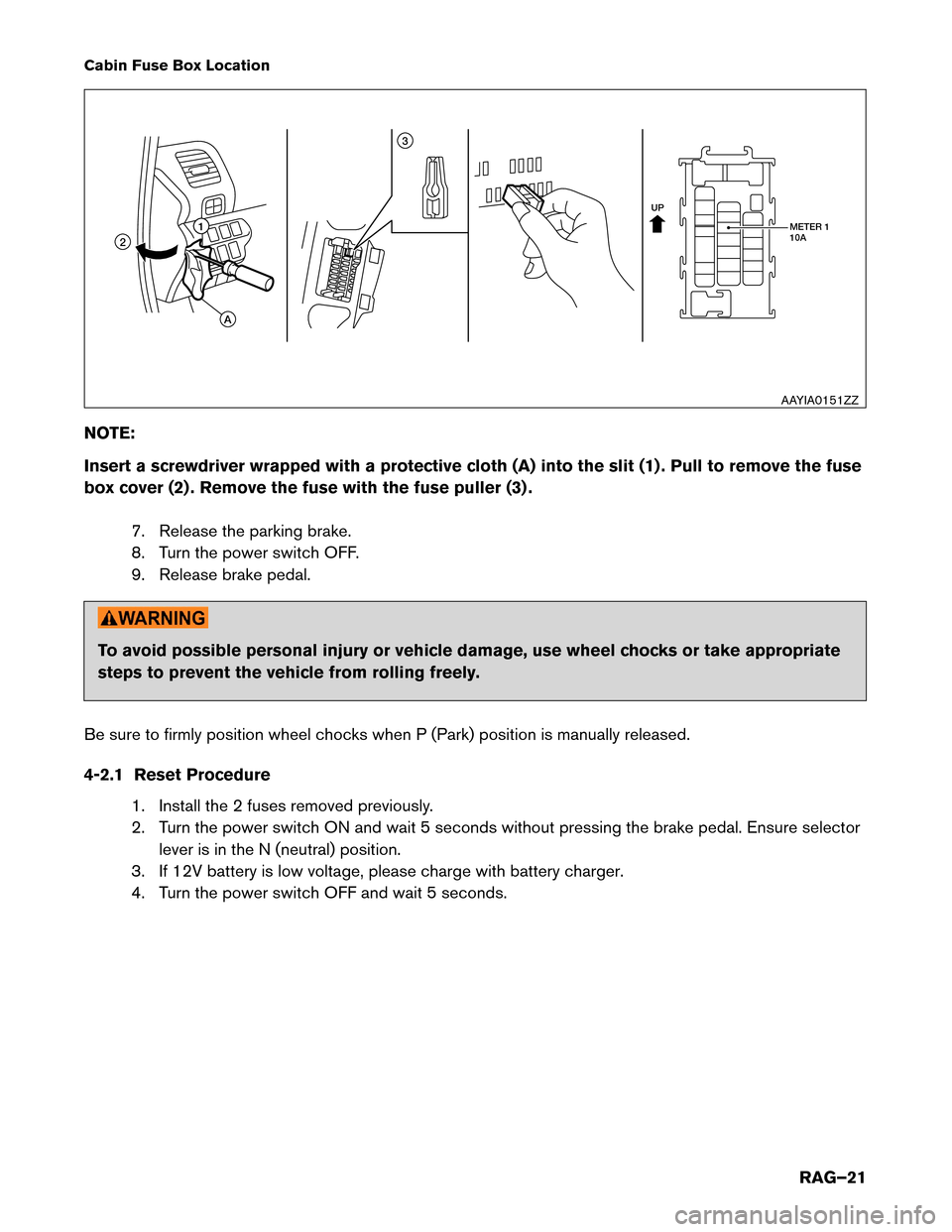
Insert a screwdriver wrapped with a protective cloth (A) into the slit (1) . Pull to remove the fuse
box cover (2) . Remove the fuse with the fuse puller (3) .
7. Release the parking brake.
8. Turn the power switch OFF.
9. Release brake pedal. To avoid possible personal injury or vehicle damage, use wheel chocks or take appropriate
steps
to prevent the vehicle from rolling freely.
Be sure to firmly position wheel chocks when P (Park) position is manually released.
4-2.1 Reset Procedure 1. Install the 2 fuses removed previously.
2. Turn the power switch ON and wait 5 seconds without pressing the brake pedal. Ensure selectorlever is in the N (neutral) position.
3. If 12V battery is low voltage, please charge with battery charger.
4. Turn the power switch OFF and wait 5 seconds. UP
METER 1
10A
11 3
2
A
AAYIA0151ZZ
RAG–21
Page 23 of 39
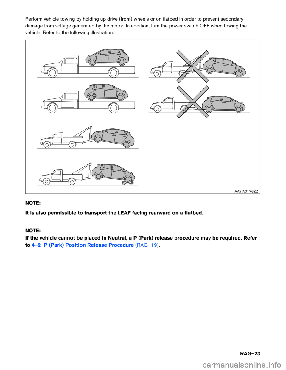
Perform vehicle towing by holding up drive (front) wheels or on flatbed in order to prevent secondary
damage
from voltage generated by the motor. In addition, turn the power switch OFF when towing the
vehicle. Refer to the following illustration:
NOTE:
It is also permissible to transport the LEAF facing rearward on a flatbed.
NOTE:
If the vehicle cannot be placed in Neutral, a P (Park) release procedure may be required. Refer
to 4–2 P (Park) Position Release Procedure (RAG–19). AAYIA0176ZZ
RAG–23
Page 24 of 39
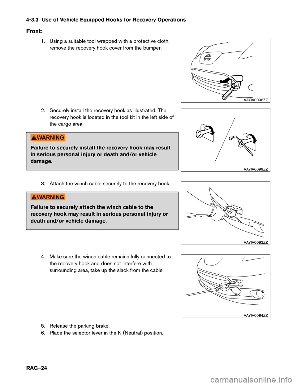
4-3.3 Use of Vehicle Equipped Hooks for Recovery Operations
Front
:1. Using a suitable tool wrapped with a protective cloth, remove the recovery hook cover from the bumper.
2. Securely install the recovery hook as illustrated. The recovery hook is located in the tool kit in the left side of
the cargo area. Failure to securely install the recovery hook may result
in
serious personal injury or death and/or vehicle
damage.
3. Attach the winch cable securely to the recovery hook. Failure to securely attach the winch cable to the
recovery
hook may result in serious personal injury or
death and/or vehicle damage.
4. Make sure the winch cable remains fully connected tothe recovery hook and does not interfere with
surrounding area, take up the slack from the cable.
5. Release the parking brake.
6. Place the selector lever in the N (Neutral) position. AAYIA0098ZZ
AAYIA0099ZZ
AAYIA0083ZZ
AAYIA0084ZZ
RAG–24
Page 25 of 39
NOTE:
If
the vehicle cannot be placed in Neutral, a P (Park) release procedure may be
required. Refer to 4–2 P (Park) Position Release Procedure (RAG–19).
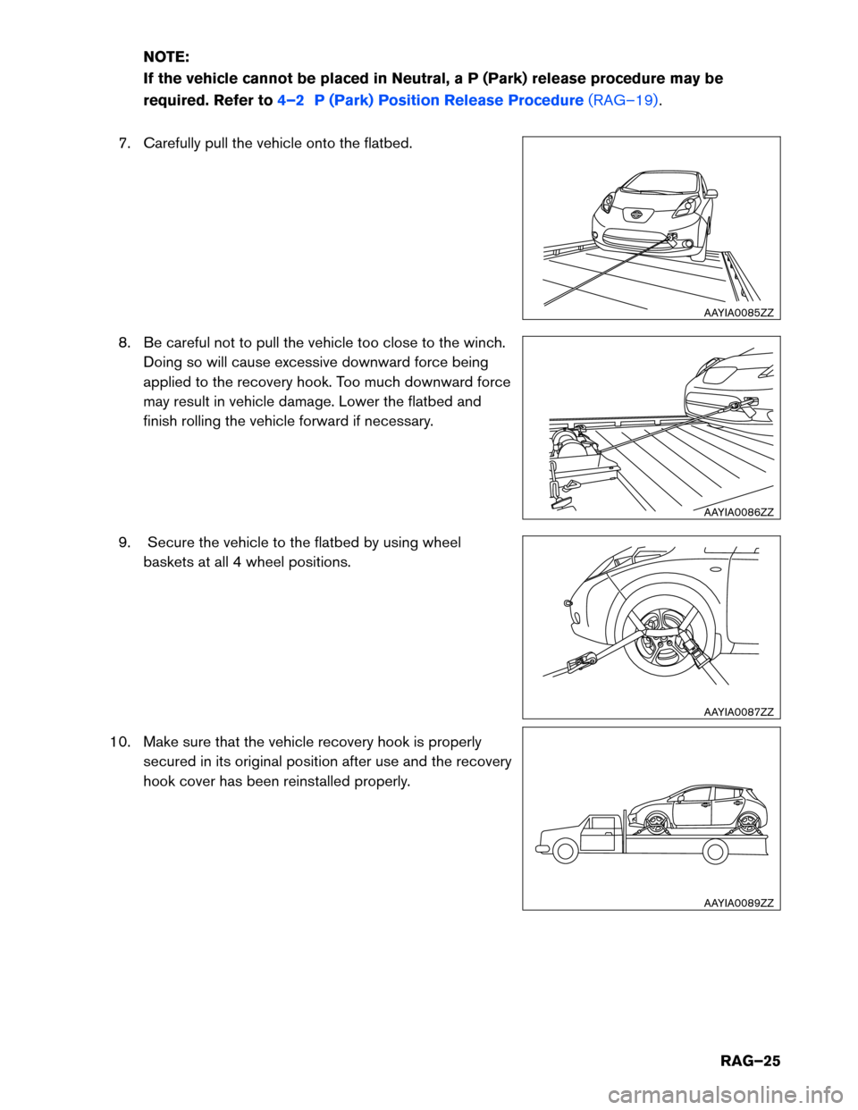
7.
Carefully pull the vehicle onto the flatbed.
8. Be careful not to pull the vehicle too close to the winch. Doing so will cause excessive downward force being
applied to the recovery hook. Too much downward force
may result in vehicle damage. Lower the flatbed and
finish rolling the vehicle forward if necessary.
9. Secure the vehicle to the flatbed by using wheel baskets at all 4 wheel positions.
10. Make sure that the vehicle recovery hook is properly secured in its original position after use and the recovery
hook cover has been reinstalled properly. AAYIA0085ZZ
AAYIA0086ZZ
AAYIA0087ZZ
AAYIA0089ZZ
RAG–25
Page 36 of 39
5-2.3 Insulated Tools
When
performing work at locations where high voltage is applied (such as terminals) , use insulated tools
meeting 1,000V/300A specifications.
5-3 Removing the Service Plug • Do not remove the service plug without always wearing appropriate Personal
Protective
Equipment (PPE) to help protect the responder from serious injury or death
by electrical shock.
• Immediately cover the service plug socket with insulated tape. The Li-ion battery
retains
high voltage power even when the service plug is removed. To avoid electric
shock, NEVER touch the terminals inside the socket. To avoid unintended reinstallation and risk of electrical shock and severe personal injury
or
death, the service plug should be securely stored away from the vehicle while the vehicle
is in storage.
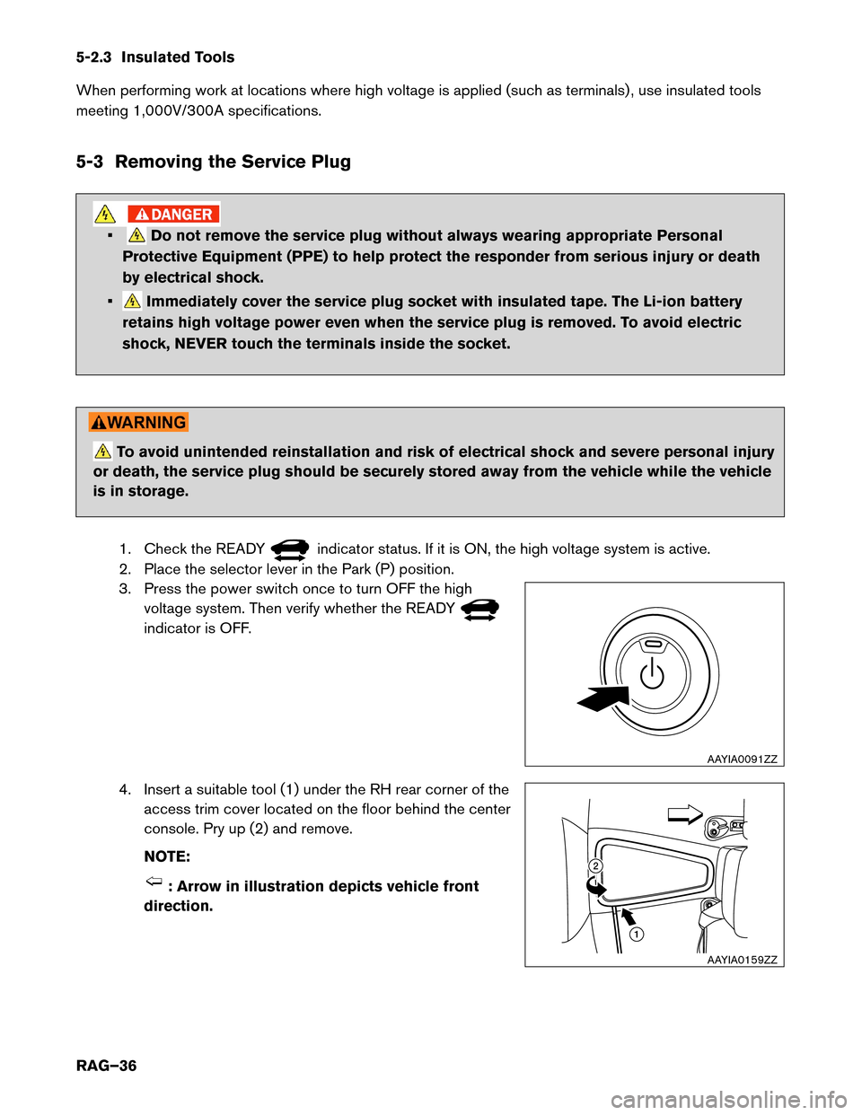
1. Check the READY indicator status. If it is ON, the high voltage system is active.
2.
Place the selector lever in the Park (P) position.
3. Press the power switch once to turn OFF the high voltage system. Then verify whether the READY indicator is OFF.
4.
Insert a suitable tool (1) under the RH rear corner of the
access trim cover located on the floor behind the center
console. Pry up (2) and remove.
NOTE: : Arrow in illustration depicts vehicle front
direction. AAYIA0091ZZ
12
AAYIA0159ZZ
RAG–36