Page 17 of 39

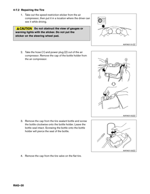
4. Roadside Assistance
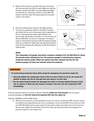
4-1
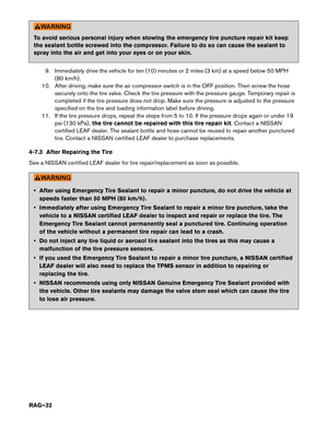
Jump Starting
To start the EV system with a booster battery, the instructions and precautions below must be followed. If done incorrectly, jump starting can lead to a 12V battery explosion, resulting in severe
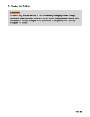
personal
injury or death. It could also damage your vehicle.
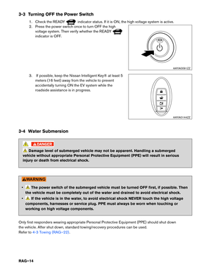
Discharged 12V battery may cause the following issues: • The instrument cluster cannot be displayed while the power switch is turned ON. The start-upsound is not audible. (The electric car system cannot start.)
• The Li-ion battery cannot be charged.
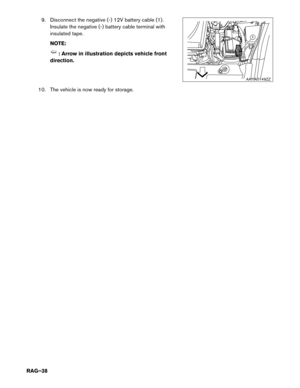
• The vehicle cannot be shifted out of PARK normally. • To avoid electrical shock, the high voltage Li-ion battery CANNOT be jump started.
•
Explosive hydrogen gas is always present in the vicinity of the 12V battery. Keep all
sparks and flames away from the 12V battery. Make sure the vent tube is correctly
installed.
• Do not allow battery fluid to come into contact with eyes, skin, clothing or painted surfaces. Battery fluid is a corrosive sulfuric acid solution that can cause severe burns. If
the fluid comes into contact with anything, immediately flush the contacted area with
water.
• The booster battery must be rated at 12 volts. Use of an improperly rated battery can damage the vehicle.
• Whenever working on or near a 12V battery, always wear suitable eye protectors (for example, goggles or industrial safety spectacles) and remove rings, metal bands, or
any other jewelry. Do not lean over the 12V battery when jump starting.
• Do not attempt to jump start a frozen battery. It could explode and cause serious injury.
• LEAF is equipped with an automatic cooling fan. It could come on at any time. Keep hands and other objects away from it.
• Always follow the jump starting instructions below. Failure to do so could result in damage to the charging system and cause personal injury. • Do not use LEAF to jump start another vehicle.
•
Do not attempt to perform a jump start on the 12V battery at the same time that the
Li-ion battery is being charged. Doing so may damage the vehicle or charging
equipment and could cause an injury.
RAG–17
Page 18 of 39
 , position the two vehicles (A and B) to bring their
12V batteries into close proximity to each other.
DO NOT allow t")
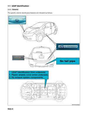
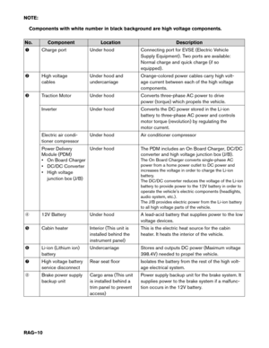
4-1.1 Jump Starting Procedures
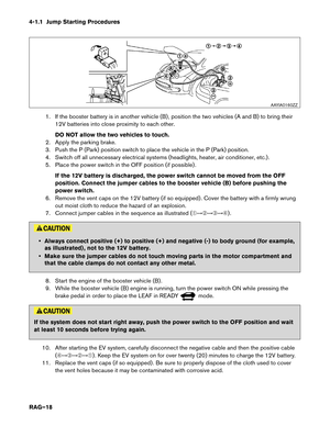
1. If the booster battery is in another vehicle (B) , position the two vehicles (A and B) to bring their
12V batteries into close proximity to each other.
DO NOT allow the two vehicles to touch.
2. Apply the parking brake.
3. Push the P (Park) position switch to place the vehicle in the P (Park) position.
4. Switch off all unnecessary electrical systems (headlights, heater, air conditioner, etc.) .
5. Place the power switch in the OFF position (if possible) .
If the 12V battery is discharged, the power switch cannot be moved from the OFF
position. Connect the jumper cables to the booster vehicle (B) before pushing the
power switch.
6. Remove the vent caps on the 12V battery (if so equipped) . Cover the battery with a firmly wrung out moist cloth to reduce the hazard of an explosion.
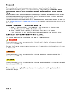
7. Connect jumper cables in the sequence as illustrated (�������) . • Always connect positive (+) to positive (+) and negative (-) to body ground (for example,
as
illustrated) , not to the 12V battery.
• Make sure the jumper cables do not touch moving parts in the motor compartment and that the cable clamps do not contact any other metal.
8. Start the engine of the booster vehicle (B) .
9. While the booster vehicle (B) engine is running, turn the power switch ON while pressing the brake pedal in order to place the LEAF in READY mode.
If the system does not start right away, push the power switch to the OFF position and wait
at
least 10 seconds before trying again.
10. After starting the EV system, carefully disconnect the negative cable and then the positive cable (�������) . Keep the EV system on for over twenty (20) minutes to charge the 12V battery.
11. Replace the vent caps (if so equipped) . Be sure to properly dispose of the cloth used to cover the vent holes because it may be contaminated with corrosive acid. AAYIA0160ZZ
RAG–18
Page 19 of 39
 to charge the Li-ion battery. The vehicle cannot be driven unless the Li-ion battery is
charged.")
12. If necessary, connect the vehicle to a charging station or EVSE (Electric Vehicle Supply
Equipment) to charge the Li-ion battery. The vehicle cannot be driven unless the Li-ion battery is
charged.
NOTE:
If it is not possible to turn the LEAF system ON by following this procedure, contact a
NISSAN certified LEAF dealer immediately.
4-2 P (Park) Position Release Procedure
If you need to release the vehicle from the P (Park) position, proceed as follows. When power switch is
turned OFF or 12V battery is low, LEAF automatically shifts to P position.
NOTE: This procedure requires two (2) people.
1. To start the EV system with a booster battery, refer to 4-1 Jump Starting (RAG–17).
2.
Turn power switch ON by pushing the power switch 2 times without pressing brake pedal.
3. Confirm parking brake is applied.
4. Close all doors and press and hold the brake pedal.
5. Place the selector lever in the N (Neutral) position.
6. Remove the following 2 fuses:
• F/L 40A PBW MTR (under hood fuse and relay box)
• METER 1 10A (in the cabin fuse box)
RAG–19
Page 20 of 39
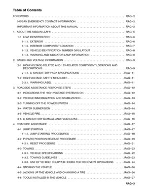
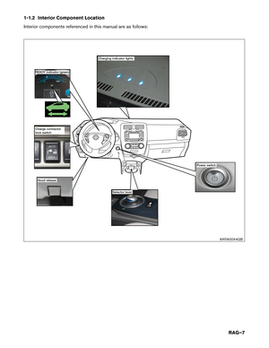
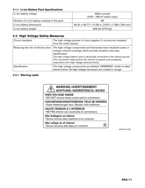
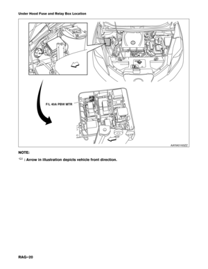
Under Hood Fuse and Relay Box Location
NO
TE: : Arrow in illustration depicts vehicle front direction. F/L 40A PBW MTR
AAYIA0163ZZ
RAG–20
Page 21 of 39
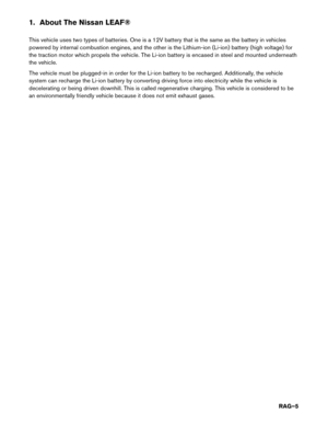
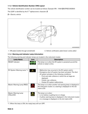
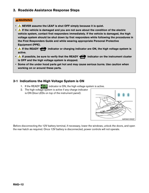
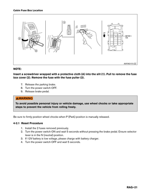
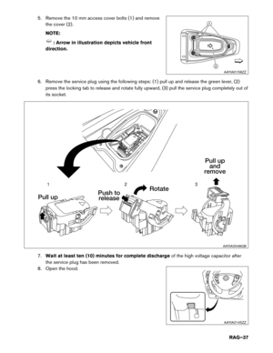
Cabin Fuse Box Location
NO
TE:
Insert a screwdriver wrapped with a protective cloth (A) into the slit (1) . Pull to remove the fuse
box cover (2) . Remove the fuse with the fuse puller (3) .
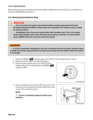
7. Release the parking brake.
8. Turn the power switch OFF.
9. Release brake pedal. To avoid possible personal injury or vehicle damage, use wheel chocks or take appropriate
steps
to prevent the vehicle from rolling freely.
Be sure to firmly position wheel chocks when P (Park) position is manually released.
4-2.1 Reset Procedure 1. Install the 2 fuses removed previously.
2. Turn the power switch ON and wait 5 seconds without pressing the brake pedal. Ensure selectorlever is in the N (neutral) position.
3. If 12V battery is low voltage, please charge with battery charger.
4. Turn the power switch OFF and wait 5 seconds. UP
METER 1
10A
11 3
2
A
AAYIA0151ZZ
RAG–21
Page 22 of 39

Width 69.7 in. (1,770 mm)
Overall Height 61.0 in. (1,550 mm)
Wheel Base 106.3 in. (2,700 mm)
Minimum ground clearance 6.3 in. (160 mm")
4-3 Towing
4-3.1
Vehicle Specifications Length
175
in. (4,445 mm)
Width 69.7 in. (1,770 mm)
Overall Height 61.0 in. (1,550 mm)
Wheel Base 106.3 in. (2,700 mm)
Minimum ground clearance 6.3 in. (160 mm)
Overall vehicle weight 3,256-3,346 lbs. (1,477-1,518 kg) (Weight varies
by equipment and trim level.)
Front approach angle 17°
Rear departure angle 26°
4-3.2 Towing Guidelines
NISSAN strongly recommends that LEAF be towed with the driving (front) wheels off the ground or that the
vehicle be placed on a flatbed truck. • Never tow with the front wheels on the ground or four (4) wheels on the ground
(forward
or backward) , as this may cause serious and expensive damage to the motor.
• Transport the vehicle only after turning the power switch OFF.
• When towing this vehicle with the rear wheels on the ground (if you do not use towing dollies) , always release the parking brake.
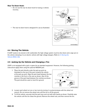
• Safety chains or cables must be attached only to the vehicle recovery hook or main structural members of the vehicle. Otherwise, the vehicle body will be damaged.
• Do not use the vehicle tie down hook to free a vehicle stuck in sand, snow, mud, etc.
• Never tow a vehicle using the vehicle tie down hook or recovery hook.
• Always pull the cable straight out from the front of the vehicle. Never pull on the vehicle at an angle.
• Pulling devices should be routed so they do not touch any part of the suspension, steering, brake, high voltage or cooling systems.
• Pulling devices such as ropes or canvas straps are not recommended for use in vehicle towing or recovery.
RAG–22
Page 23 of 39
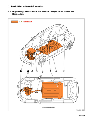
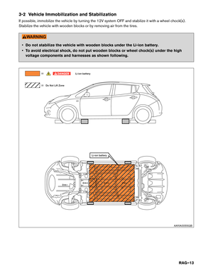
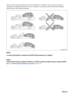
Perform vehicle towing by holding up drive (front) wheels or on flatbed in order to prevent secondary
damage
from voltage generated by the motor. In addition, turn the power switch OFF when towing the
vehicle. Refer to the following illustration:
NOTE:
It is also permissible to transport the LEAF facing rearward on a flatbed.
NOTE:
If the vehicle cannot be placed in Neutral, a P (Park) release procedure may be required. Refer
to 4–2 P (Park) Position Release Procedure (RAG–19). AAYIA0176ZZ
RAG–23
Page 24 of 39
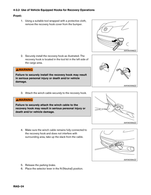
4-3.3 Use of Vehicle Equipped Hooks for Recovery Operations
Front
:1. Using a suitable tool wrapped with a protective cloth, remove the recovery hook cover from the bumper.
2. Securely install the recovery hook as illustrated. The recovery hook is located in the tool kit in the left side of
the cargo area. Failure to securely install the recovery hook may result
in
serious personal injury or death and/or vehicle
damage.
3. Attach the winch cable securely to the recovery hook. Failure to securely attach the winch cable to the
recovery
hook may result in serious personal injury or
death and/or vehicle damage.
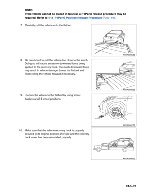
4. Make sure the winch cable remains fully connected tothe recovery hook and does not interfere with
surrounding area, take up the slack from the cable.
5. Release the parking brake.
6. Place the selector lever in the N (Neutral) position. AAYIA0098ZZ
AAYIA0099ZZ
AAYIA0083ZZ
AAYIA0084ZZ
RAG–24


 into the slit (1) . Pull to remove the fuse
box cover (2) . Remove the fuse with the fuse puller (3) .
7. Releas")
 wheels or on flatbed in order to prevent secondary
damage
from voltage generated by the motor. In addition, turn the power switch OFF when towing the")
