Page 111 of 402
2-36Instruments and controls
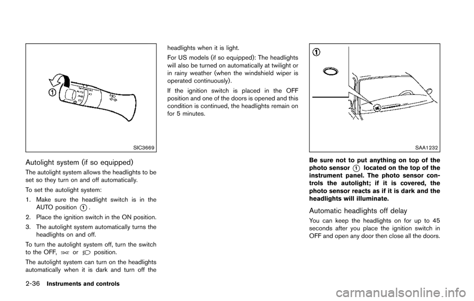
SIC3669
Autolight system (if so equipped)
The autolight system allows the headlights to be
set so they turn on and off automatically.
To set the autolight system:
1. Make sure the headlight switch is in theAUTO position
*1.
2. Place the ignition switch in the ON position.
3. The autolight system automatically turns the headlights on and off.
To turn the autolight system off, turn the switch
to the OFF,
orposition.
The autolight system can turn on the headlights
automatically when it is dark and turn off the headlights when it is light.
For US models (if so equipped): The headlights
will also be turned on automatically at twilight or
in rainy weather (when the windshield wiper is
operated continuously) .
If the ignition switch is placed in the OFF
position and one of the doors is opened and this
condition is continued, the headlights remain on
for 5 minutes.
SAA1232
Be sure not to put anything on top of the
photo sensor
*1located on the top of the
instrument panel. The photo sensor con-
trols the autolight; if it is covered, the
photo sensor reacts as if it is dark and the
headlights will illuminate.
Automatic headlights off delay
You can keep the headlights on for up to 45
seconds after you place the ignition switch in
OFF and open any door then close all the doors.
Page 113 of 402
2-38Instruments and controls
SIC4517
SIC4129
Instrument brightness control
The instrument brightness control operates
when the ignition switch is in the ON position.
Push the control knob
*Ato adjust the bright-
ness of the instrument panel lights. The bright-
ness indicator
*Bwill be shown briefly in the
vehicle information display when the control is
turned.
When the brightness level reaches the maximum
or minimum, a beep will sound.
SIC3671
TURN SIGNAL SWITCH
*1Turn signal
Move the lever up or down to signal the turning
direction. When the turn is completed, the turn
signals cancel automatically.
*2Lane change signal
To indicate a lane change, move the lever up or
down to the point where lights begin flashing.
Page 117 of 402
2-42Instruments and controls
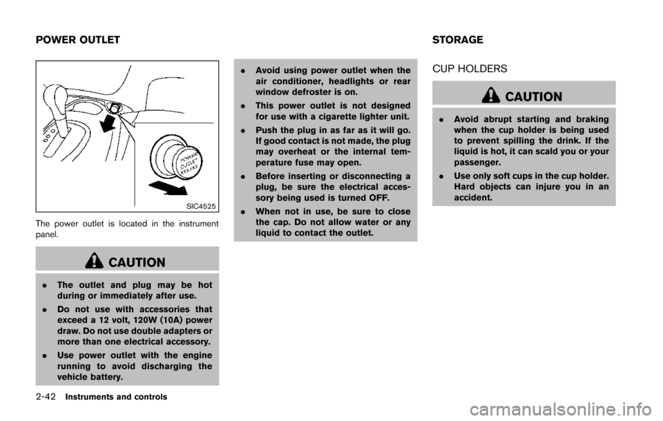
SIC4525
The power outlet is located in the instrument
panel.
CAUTION
.The outlet and plug may be hot
during or immediately after use.
. Do not use with accessories that
exceed a 12 volt, 120W (10A) power
draw. Do not use double adapters or
more than one electrical accessory.
. Use power outlet with the engine
running to avoid discharging the
vehicle battery. .
Avoid using power outlet when the
air conditioner, headlights or rear
window defroster is on.
. This power outlet is not designed
for use with a cigarette lighter unit.
. Push the plug in as far as it will go.
If good contact is not made, the plug
may overheat or the internal tem-
perature fuse may open.
. Before inserting or disconnecting a
plug, be sure the electrical acces-
sory being used is turned OFF.
. When not in use, be sure to close
the cap. Do not allow water or any
liquid to contact the outlet.
CUP HOLDERS
CAUTION
.Avoid abrupt starting and braking
when the cup holder is being used
to prevent spilling the drink. If the
liquid is hot, it can scald you or your
passenger.
. Use only soft cups in the cup holder.
Hard objects can injure you in an
accident.
POWER OUTLET STORAGE
Page 146 of 402
WARNING
.Make sure the hood is completely
closed and latched before driving.
Failure to do so could cause the
hood to fly open and result in an
accident.
. If you see steam or smoke coming
from the engine compartment, to
avoid injury do not open the hood.
SPA2798
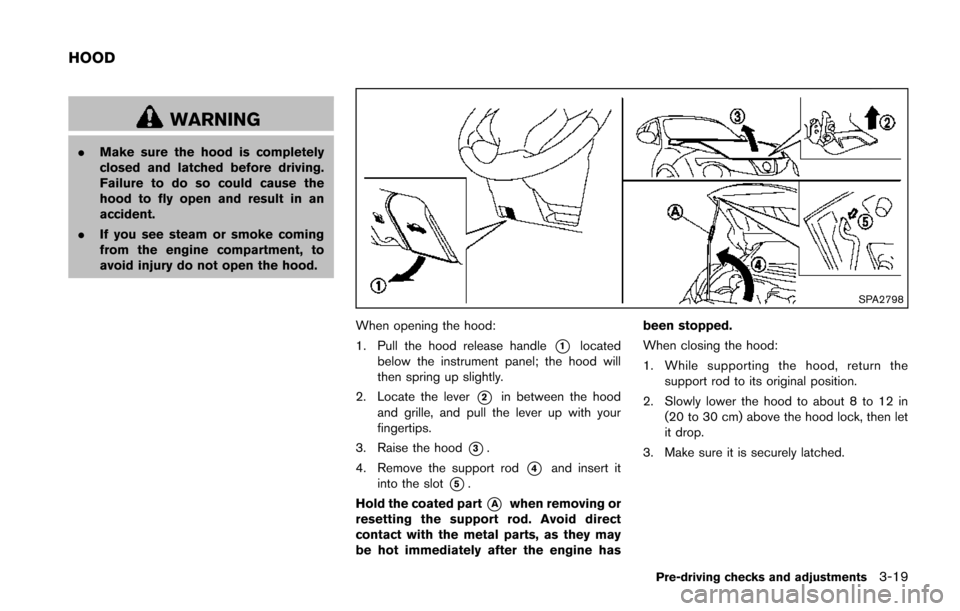
When opening the hood:
1. Pull the hood release handle
*1located
below the instrument panel; the hood will
then spring up slightly.
2. Locate the lever
*2in between the hood
and grille, and pull the lever up with your
fingertips.
3. Raise the hood
*3.
4. Remove the support rod
*4and insert it
into the slot
*5.
Hold the coated part
*Awhen removing or
resetting the support rod. Avoid direct
contact with the metal parts, as they may
be hot immediately after the engine has been stopped.
When closing the hood:
1. While supporting the hood, return the
support rod to its original position.
2. Slowly lower the hood to about 8 to 12 in (20 to 30 cm) above the hood lock, then let
it drop.
3. Make sure it is securely latched.
Pre-driving checks and adjustments3-19
HOOD
Page 148 of 402
JVP0208X
CAUTION
Do not place your foot on or step on the
front bumper. Also, do not step on the
side sill extensions when getting in or
out of the vehicle. Doing so may result
in damage to the front bumper and side
sill extensions.
SPA2336
OPENING THE FUEL-FILLER DOOR
To open the fuel-filler door, pull the release
handle located below the instrument panel. To
lock, close the fuel-filler door securely.
SPA2800
FUEL-FILLER CAP
To remove the fuel-filler cap:
1. Turn the fuel-filler cap counterclockwise
*1to remove.
2. Put the fuel-filler cap on the cap holder
*Awhile refueling.
To install the fuel-filler cap:
1. Insert the fuel-filler cap straight into the fuel- filler tube.
2. Turn the fuel-filler cap clockwise
*2until a
single click is heard.
Pre-driving checks and adjustments3-21
FUEL-FILLER DOOR
Page 153 of 402
3-26Pre-driving checks and adjustments
SPA2214
Adjusting outside mirrors
The outside mirror control switch is located at
the lower part of the instrument panel.
The outside mirror will operate only when the
ignition switch is in the ACC or ON position.
Move the switch right
*1or left*2to select
the right or left side mirror, then adjust
*3using
the control switch.
Defrosting outside mirrors (if so
equipped)
The outside mirrors will be heated when the rear
window defroster switch is operated. (See “Rear
window and outside mirror defroster switch”
(P.2-35) .)
SPA1829
Foldable outside mirrors
Fold the outside mirror by pushing it toward the
rear of the vehicle.
Page 182 of 402
SAA2368
SAA3441
OPERATING TIPS (for automatic air
conditioner)
.When the engine coolant temperature and
outside air temperature are low, the air flow
from the foot outlets may not operate. This is
not a malfunction. After the coolant tem-
perature warms up, air will flow normally
from the foot outlets.
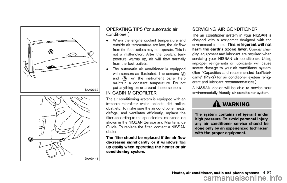
. The automatic air conditioner is equipped
with sensors as illustrated. The sensors
*Aand*Bon the instrument panel help
maintain a constant temperature. Do not
put anything on or around these sensors.
IN-CABIN MICROFILTER
The air conditioning system is equipped with an
in-cabin microfilter which collects dirt, pollen,
dust, etc. To make sure the air conditioner heats,
defogs, and ventilates efficiently, replace the
filter according to the specified maintenance log
shown in the NISSAN Service and Maintenance
Guide. To replace the filter, contact a NISSAN
dealer.
The filter should be replaced if the air flow
decreases significantly or if windows fog
up easily when operating the heater or air
conditioning system.
SERVICING AIR CONDITIONER
The air conditioner system in your NISSAN is
charged with a refrigerant designed with the
environment in mind. This refrigerant will not
harm the earth’s ozone layer. Special char-
ging equipment and lubricant are required when
servicing your NISSAN air conditioner. Using
improper refrigerants or lubricants will cause
severe damage to your air conditioner system.
(See “Capacities and recommended fuel/lubri-
cants” (P.9-2) for air conditioner system refrig-
erant and lubricant recommendations.)
A NISSAN dealer will be able to service your
environmentally friendly air conditioner system.
WARNING
The system contains refrigerant under
high pressure. To avoid personal injury,
any air conditioner service should be
done only by an experienced technician
with the proper equipment.
Heater, air conditioner, audio and phone systems4-27
Page 207 of 402
4-52Heater, air conditioner, audio and phone systems
JVH0370X
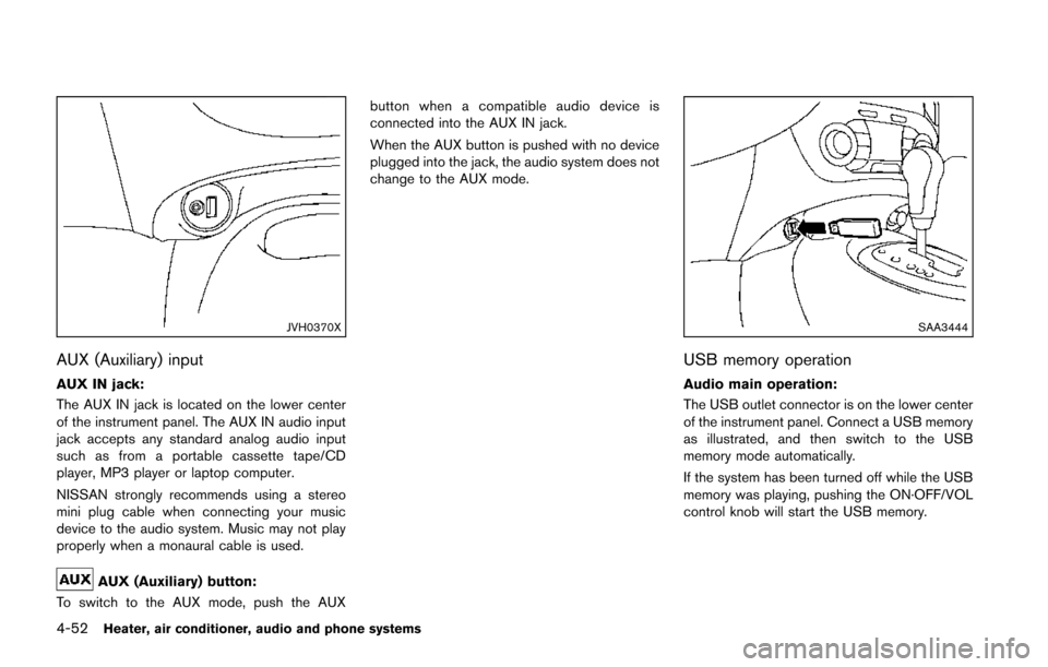
AUX (Auxiliary) input
AUX IN jack:
The AUX IN jack is located on the lower center
of the instrument panel. The AUX IN audio input
jack accepts any standard analog audio input
such as from a portable cassette tape/CD
player, MP3 player or laptop computer.
NISSAN strongly recommends using a stereo
mini plug cable when connecting your music
device to the audio system. Music may not play
properly when a monaural cable is used.
AUX (Auxiliary) button:
To switch to the AUX mode, push the AUX button when a compatible audio device is
connected into the AUX IN jack.
When the AUX button is pushed with no device
plugged into the jack, the audio system does not
change to the AUX mode.
SAA3444
USB memory operation
Audio main operation:
The USB outlet connector is on the lower center
of the instrument panel. Connect a USB memory
as illustrated, and then switch to the USB
memory mode automatically.
If the system has been turned off while the USB
memory was playing, pushing the ON·OFF/VOL
control knob will start the USB memory.