2014 NISSAN GT-R vehicle dynamic control
[x] Cancel search: vehicle dynamic controlPage 98 of 354
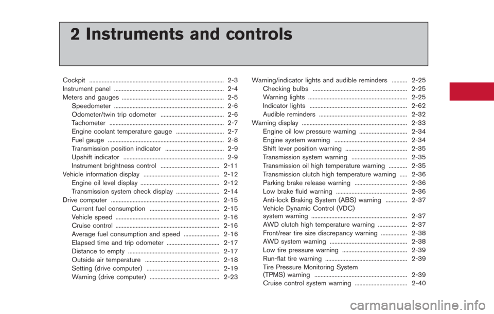
2 Instruments and controls
Cockpit ........................................................................\
............... 2-3
Instrument panel ....................................................................... 2-4
Meters and gauges .................................................................. 2-5Speedometer ....................................................................... 2-6
Odometer/twin trip odometer ......................................... 2-6
Tachometer ........................................................................\
.. 2-7
Engine coolant temperature gauge ............................... 2-7
Fuel gauge ........................................................................\
... 2-8
Transmission position indicator ...................................... 2-9
Upshift indicator ................................................................. 2-9
Instrument brightness control ...................................... 2-11
Vehicle information display ................................................. 2-12 Engine oil level display ................................................... 2-12
Transmission system check display ............................ 2-14
Drive computer ...................................................................... 2-15 Current fuel consumption ............................................. 2-15
Vehicle speed ................................................................... 2-16
Cruise control ................................................................... 2-16
Average fuel consumption and speed ....................... 2-16
Elapsed time and trip odometer .................................. 2-17
Distance to empty ........................................................... 2-17
Outside air temperature ................................................ 2-18
Setting (drive computer) ............................................... 2-19
Warning (drive computer) ............................................. 2-23 Warning/indicator lights and audible reminders .......... 2-25
Checking bulbs ............................................................. 2-25
Warning lights ................................................................ 2-25
Indicator lights ............................................................... 2-62
Audible reminders ......................................................... 2-32
Warning display .................................................................... 2-33
Engine oil low pressure warning ............................... 2-34
Engine system warning ............................................... 2-34
Shift lever position warning ........................................ 2-35
Transmission system warning .................................... 2-35
Transmission oil high temperature warning ............ 2-35
Transmission clutch high temperature warning ..... 2-36Parking brake release warning .................................. 2-36
Low brake fluid warning .............................................. 2-36
Anti-lock Braking System (ABS) warning .............. 2-37
Vehicle Dynamic Control (VDC)
system warning .............................................................. 2-37
AWD clutch high temperature warning ................... 2-37
Front/rear tire size discrepancy warning ................. 2-38
AWD system warning .................................................. 2-38
Low tire pressure warning .......................................... 2-39
Run-flat tire warning ..................................................... 2-39Tire Pressure Monitoring System
(TPMS) warning ............................................................ 2-39
Cruise control system warning .................................. 2-40
Page 122 of 354
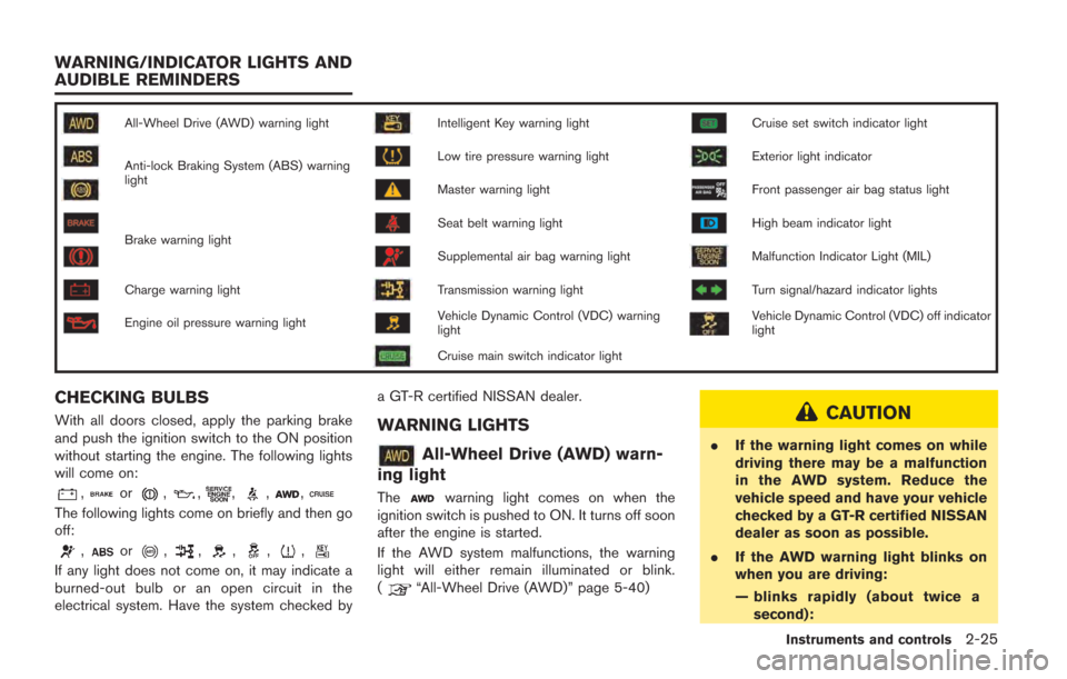
All-Wheel Drive (AWD) warning lightIntelligent Key warning lightCruise set switch indicator light
Anti-lock Braking System (ABS) warning
lightLow tire pressure warning lightExterior light indicator
Master warning lightFront passenger air bag status light
Brake warning lightSeat belt warning lightHigh beam indicator light
Supplemental air bag warning lightMalfunction Indicator Light (MIL)
Charge warning lightTransmission warning lightTurn signal/hazard indicator lights
Engine oil pressure warning lightVehicle Dynamic Control (VDC) warning
lightVehicle Dynamic Control (VDC) off indicator
light
Cruise main switch indicator light
CHECKING BULBS
With all doors closed, apply the parking brake
and push the ignition switch to the ON position
without starting the engine. The following lights
will come on:
,or,,,,,
The following lights come on briefly and then go
off:
,or,,,,,
If any light does not come on, it may indicate a
burned-out bulb or an open circuit in the
electrical system. Have the system checked bya GT-R certified NISSAN dealer.
WARNING LIGHTS
All-Wheel Drive (AWD) warn-
ing light
Thewarning light comes on when the
ignition switch is pushed to ON. It turns off soon
after the engine is started.
If the AWD system malfunctions, the warning
light will either remain illuminated or blink.
(
“All-Wheel Drive (AWD)” page 5-40)
CAUTION
. If the warning light comes on while
driving there may be a malfunction
in the AWD system. Reduce the
vehicle speed and have your vehicle
checked by a GT-R certified NISSAN
dealer as soon as possible.
. If the AWD warning light blinks on
when you are driving:
— blinks rapidly (about twice a
second):
Instruments and controls2-25
WARNING/INDICATOR LIGHTS AND
AUDIBLE REMINDERS
Page 128 of 354
When the warning light illuminates, perform cool
down driving (driving 1.3 mile (2 km) in 5th or
6th gear at a speed of approximately 37 - 50
MPH (60 - 80 km/h) while checking the
temperature of the transmission oil until the
warning light goes off.
NOTICE
While the warning light is illuminated,
the engine output is controlled so that
it does not increase.
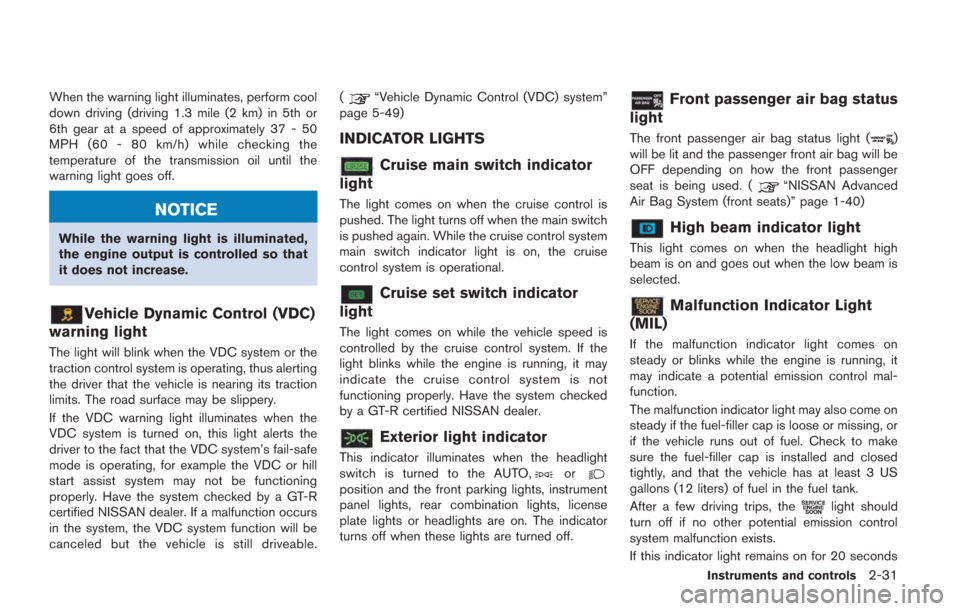
Vehicle Dynamic Control (VDC)
warning light
The light will blink when the VDC system or the
traction control system is operating, thus alerting
the driver that the vehicle is nearing its traction
limits. The road surface may be slippery.
If the VDC warning light illuminates when the
VDC system is turned on, this light alerts the
driver to the fact that the VDC system’s fail-safe
mode is operating, for example the VDC or hill
start assist system may not be functioning
properly. Have the system checked by a GT-R
certified NISSAN dealer. If a malfunction occurs
in the system, the VDC system function will be
canceled but the vehicle is still driveable. (
“Vehicle Dynamic Control (VDC) system”
page 5-49)
INDICATOR LIGHTS
Cruise main switch indicator
light
The light comes on when the cruise control is
pushed. The light turns off when the main switch
is pushed again. While the cruise control system
main switch indicator light is on, the cruise
control system is operational.
Cruise set switch indicator
light
The light comes on while the vehicle speed is
controlled by the cruise control system. If the
light blinks while the engine is running, it may
indicate the cruise control system is not
functioning properly. Have the system checked
by a GT-R certified NISSAN dealer.
Exterior light indicator
This indicator illuminates when the headlight
switch is turned to the AUTO,orposition and the front parking lights, instrument
panel lights, rear combination lights, license
plate lights or headlights are on. The indicator
turns off when these lights are turned off.
Front passenger air bag status
light
The front passenger air bag status light ()
will be lit and the passenger front air bag will be
OFF depending on how the front passenger
seat is being used. (
“NISSAN Advanced
Air Bag System (front seats)” page 1-40)
High beam indicator light
This light comes on when the headlight high
beam is on and goes out when the low beam is
selected.
Malfunction Indicator Light
(MIL)
If the malfunction indicator light comes on
steady or blinks while the engine is running, it
may indicate a potential emission control mal-
function.
The malfunction indicator light may also come on
steady if the fuel-filler cap is loose or missing, or
if the vehicle runs out of fuel. Check to make
sure the fuel-filler cap is installed and closed
tightly, and that the vehicle has at least 3 US
gallons (12 liters) of fuel in the fuel tank.
After a few driving trips, the
light should
turn off if no other potential emission control
system malfunction exists.
If this indicator light remains on for 20 seconds
Instruments and controls2-31
Page 129 of 354
2-32Instruments and controls
and then blinks for 10 seconds when the engine
is not running, it indicates that the vehicle is not
ready for an emission control system inspection/
maintenance test. (
“Readiness for Inspec-
tion/Maintenance (I/M) test (US only)” page 9-
20)
Operation:
The malfunction indicator light will come on in
one of two ways:
. Malfunction indicator light on steady — An
emission control system malfunction has
been detected. Check the fuel-filler cap. If
the fuel-filler cap is loose or missing, tighten
or install the cap and continue to drive the
vehicle. The
light should turn off after a
few driving trips. If thelight does not
turn off after a few driving trips, have the
vehicle inspected by a GT-R certified
NISSAN dealer. You do not need to have
your vehicle towed to the dealer.
. Malfunction indicator light blinking — An
engine misfire has been detected which may
damage the emission control system.
To reduce or avoid emission control system
damage:
a. Do not drive at speeds above 45 MPH
(72 km/h). b. Avoid hard acceleration or deceleration.
c. Avoid steep uphill grades.
d. If possible, reduce the amount of cargo
being hauled or towed.
The malfunction indicator light may stop
blinking and remain on.
Have the vehicle inspected by a GT-R
certified NISSAN dealer. You do not need
to have your vehicle towed to the dealer.
NOTICE
Continued vehicle operation without
having the emission control system
checked and repaired as necessary
could lead to poor driveability, reduced
fuel economy, and possible damage to
the emission control system.
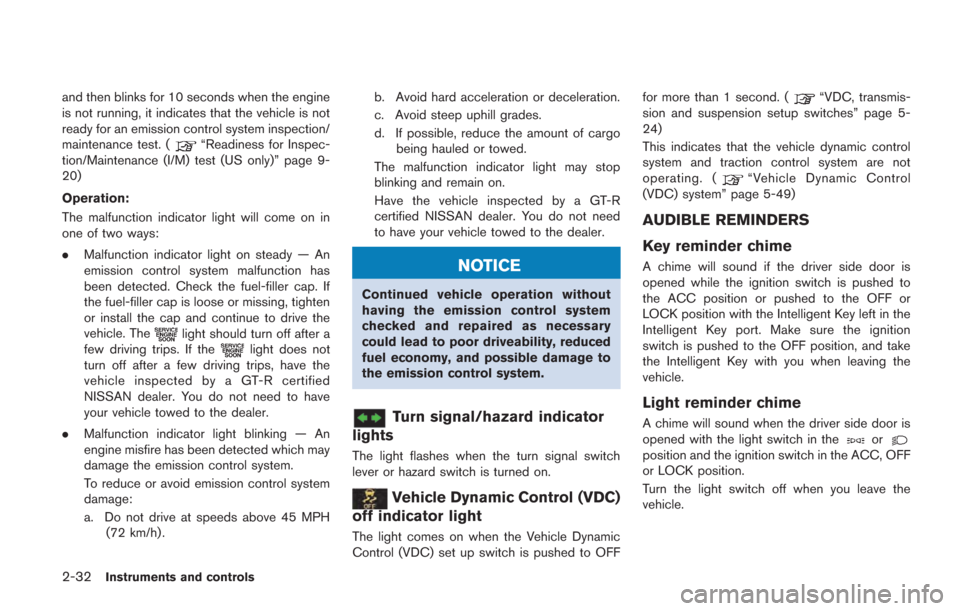
Turn signal/hazard indicator
lights
The light flashes when the turn signal switch
lever or hazard switch is turned on.
Vehicle Dynamic Control (VDC)
off indicator light
The light comes on when the Vehicle Dynamic
Control (VDC) set up switch is pushed to OFF for more than 1 second. (
“VDC, transmis-
sion and suspension setup switches” page 5-
24)
This indicates that the vehicle dynamic control
system and traction control system are not
operating. (
“Vehicle Dynamic Control
(VDC) system” page 5-49)
AUDIBLE REMINDERS
Key reminder chime
A chime will sound if the driver side door is
opened while the ignition switch is pushed to
the ACC position or pushed to the OFF or
LOCK position with the Intelligent Key left in the
Intelligent Key port. Make sure the ignition
switch is pushed to the OFF position, and take
the Intelligent Key with you when leaving the
vehicle.
Light reminder chime
A chime will sound when the driver side door is
opened with the light switch in theorposition and the ignition switch in the ACC, OFF
or LOCK position.
Turn the light switch off when you leave the
vehicle.
Page 134 of 354
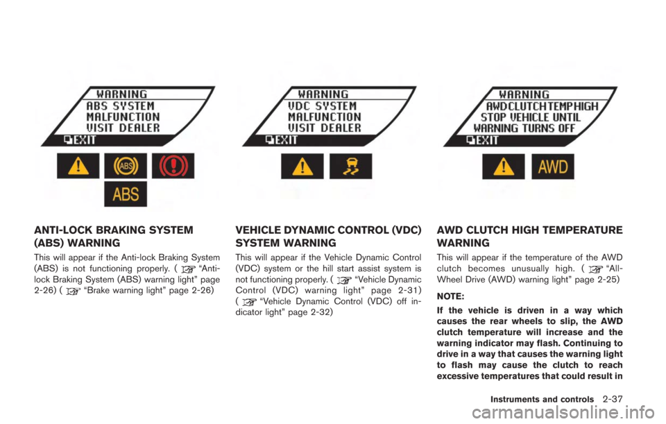
ANTI-LOCK BRAKING SYSTEM
(ABS) WARNING
This will appear if the Anti-lock Braking System
(ABS) is not functioning properly. (“Anti-
lock Braking System (ABS) warning light” page
2-26) (
“Brake warning light” page 2-26)
VEHICLE DYNAMIC CONTROL (VDC)
SYSTEM WARNING
This will appear if the Vehicle Dynamic Control
(VDC) system or the hill start assist system is
not functioning properly. (
“Vehicle Dynamic
Control (VDC) warning light” page 2-31)
(
“Vehicle Dynamic Control (VDC) off in-
dicator light” page 2-32)
AWD CLUTCH HIGH TEMPERATURE
WARNING
This will appear if the temperature of the AWD
clutch becomes unusually high. (“All-
Wheel Drive (AWD) warning light” page 2-25)
NOTE:
If the vehicle is driven in a way which
causes the rear wheels to slip, the AWD
clutch temperature will increase and the
warning indicator may flash. Continuing to
drive in a way that causes the warning light
to flash may cause the clutch to reach
excessive temperatures that could result in
Instruments and controls2-37
Page 199 of 354
Brake assist ........................................................................\
.... 5-48Anti-lock Braking System (ABS) ................................ 5-48
Vehicle Dynamic Control (VDC) system ......................... 5-49
Cold weather driving ............................................................ 5-51
Freeing a frozen door lock ............................................ 5-51
Anti-freeze ........................................................................\
. 5-51 Battery ........................................................................\
...... 5-51
Draining of coolant water ............................................ 5-51
Tire equipment ............................................................... 5-52
Special winter equipment ........................................... 5-52
Driving on snow or ice ................................................ 5-52
Engine block heater (if so equipped) ...................... 5-53
Page 221 of 354
5-24Starting and driving
the brakes normally based on traffic and road
conditions.
The metallic brake pads and brake disc rotor
may rust together when the brakes are not
applied:
.If the vehicle is not idled for 20 seconds
without the brakes applied, or if the brakes
are applied when the vehicle is shut off, the
rotor and pads can rust together, even when
the brake pads are dry.
. If the brakes are wet when the vehicle is
parked and the parking brake is applied for a
long time.
Contact a GT-R certified NISSAN dealer if the
brake pads and brake rotor have rusted
together.
1. Bring the vehicle to a complete stop.
2. With the foot brake pedal depressed, apply the parking brake.
3. Move the shift lever to the
&Pposition.
4. Check the shift lever position indicator on the instrument panel to confirm that the
&P
position is selected.
5. Push the ignition switch to stop the engine.
WARNING
Before exiting the vehicle, be sure to
move the shift lever to the&Pposition
and stop the engine. If the engine is
running and the shift lever is not in the
&Pposition, the vehicle may start mov-
ing due to partial engagement of the
clutch or to the effects of gravity on a
slope, or the vehicle may suddenly
accelerate due to accidental operation
of the accelerator pedal, possibly caus-
ing an accident.
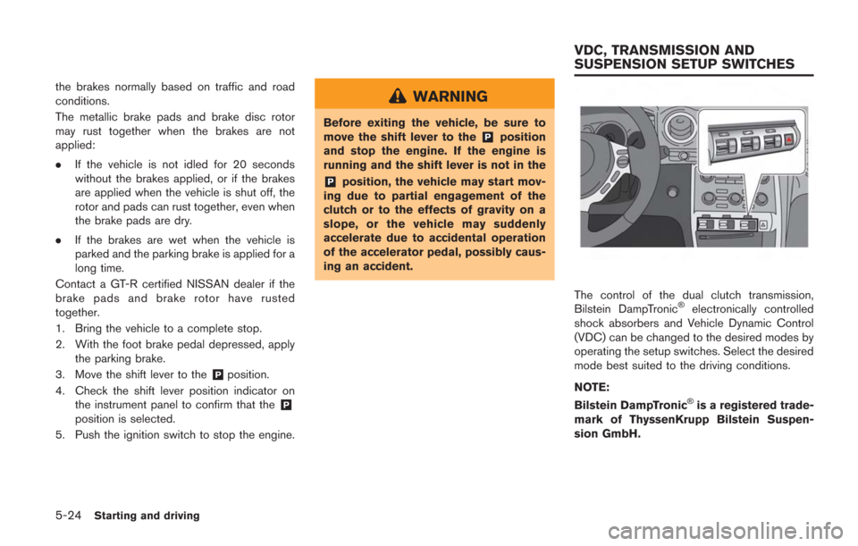
The control of the dual clutch transmission,
Bilstein DampTronic®electronically controlled
shock absorbers and Vehicle Dynamic Control
(VDC) can be changed to the desired modes by
operating the setup switches. Select the desired
mode best suited to the driving conditions.
NOTE:
Bilstein DampTronic
®is a registered trade-
mark of ThyssenKrupp Bilstein Suspen-
sion GmbH.
VDC, TRANSMISSION AND
SUSPENSION SETUP SWITCHES
Page 222 of 354
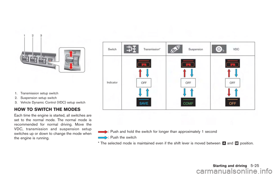
1. Transmission setup switch
2. Suspension setup switch
3. Vehicle Dynamic Control (VDC) setup switch
HOW TO SWITCH THE MODES
Each time the engine is started, all switches are
set to the normal mode. The normal mode is
recommended for normal driving. Move the
VDC, transmission and suspension setup
switches up or down to change the mode when
the engine is running.
: Push and hold the switch for longer than approximately 1 second
: Push the switch
* The selected mode is maintained even if the shift lever is moved between
&Aand&Mposition.
Starting and driving5-25