2014 NISSAN GT-R Power steering
[x] Cancel search: Power steeringPage 198 of 354
5 Starting and driving
Precautions when starting and driving ............................... 5-3Exhaust gas (carbon monoxide) ..................................... 5-3Three-way catalyst ............................................................. 5-3
Tire Pressure Monitoring System (TPMS) ................... 5-4
Avoiding collision and rollover ........................................ 5-7
Off-road recovery ............................................................... 5-7
Rapid air pressure loss ..................................................... 5-8
Drinking alcohol/drugs and driving ................................ 5-8All-Wheel Drive (AWD) driving safety precautions .... 5-9
Push-button ignition switch ................................................... 5-9
Operating range for engine start ................................ 5-10
Ignition switch operation ............................................... 5-10
Ignition switch positions ................................................ 5-10
Emergency engine shut off ........................................... 5-11
Intelligent Key battery discharge ................................. 5-11
Before starting the engine .................................................. 5-13
Starting the engine ............................................................... 5-13
Driving the vehicle ................................................................ 5-15 Dual clutch transmission ............................................... 5-15
Driving tips ........................................................................\
5-21
VDC, transmission and suspension setup switches .... 5-24 How to switch the modes ............................................ 5-25
Features of each mode .................................................. 5-26
Turbocharger system ............................................................ 5-30 R mode start function ......................................................... 5-31
How to use R mode start function ........................... 5-32
Parking brake ........................................................................\
. 5-32
Cruise control ........................................................................\
5-33 Precautions on cruise control .................................... 5-34Steering-wheel-mounted controls ............................ 5-34
Indicators and display .................................................. 5-35
Cruise control operations ........................................... 5-35
Hill Start Assist ..................................................................... 5-37
Break-in schedule ................................................................ 5-38
Wheel alignment ........................................................... 5-38
Fuel Efficient Driving Tips .................................................. 5-39
Increasing fuel economy ..................................................... 5-40
All-Wheel Drive (AWD) ...................................................... 5-40 AWD warning light ....................................................... 5-40
Tight corner braking phenomenon ........................... 5-42
Tires ........................................................................\
.......... 5-43AWD system characteristics ...................................... 5-43
Limited Slip Differential (LSD) .......................................... 5-44
Parking/parking on hills ....................................................... 5-45
Power steering ...................................................................... 5-46
Brake system ........................................................................\
. 5-47 Braking precautions ..................................................... 5-47
Parking brake break-in ................................................. 5-47
Page 208 of 354
NOTE:
.If the steering lock release malfunction
indicator appears on the vehicle infor-
mation display when the ignition
switch is pressed, press the ignition
switch again while gently turning the
steering wheel left and right.
(
“Steering lock release malfunc-
tion indicator” page 2-43)
. If the shift
&Pwarning appears on the
vehicle information display when the
ignition switch is pushed, the shift lever
is in any position except the
&Pposi-
tion. Move the shift lever to the&P
position. (“Shift “P” warning”
page 2-43)
. If the Intelligent Key battery discharge
indicator appears on the vehicle infor-
mation display, the Intelligent Key
battery is discharged and the ignition
switch will not operate. Insert the
Intelligent Key into the key port to
operate the ignition switch.
(
“Intelligent Key battery discharge
indicator” page 2-44)
. When all of the following conditions
are met for 60 minutes, the battery
saver system will cut off the power
supply to prevent battery discharge. —
The ignition switch is in the ACC
position, and
— All doors are closed, and
— The shift lever is in the
&Pposition.
. Do not leave the vehicle with the
ignition switch in the ACC or ON
position when the engine is not run-
ning for an extended period of time.
This can discharge the battery.
EMERGENCY ENGINE SHUT OFF
To shut off the engine in an emergency situation
while driving, perform the following procedure:
.Rapidly push the push-button ignition switch
3 consecutive times in less than 1.5
seconds, or
. Push and hold the push button ignition
switch for more than 2 seconds.
INTELLIGENT KEY BATTERY DIS-
CHARGE
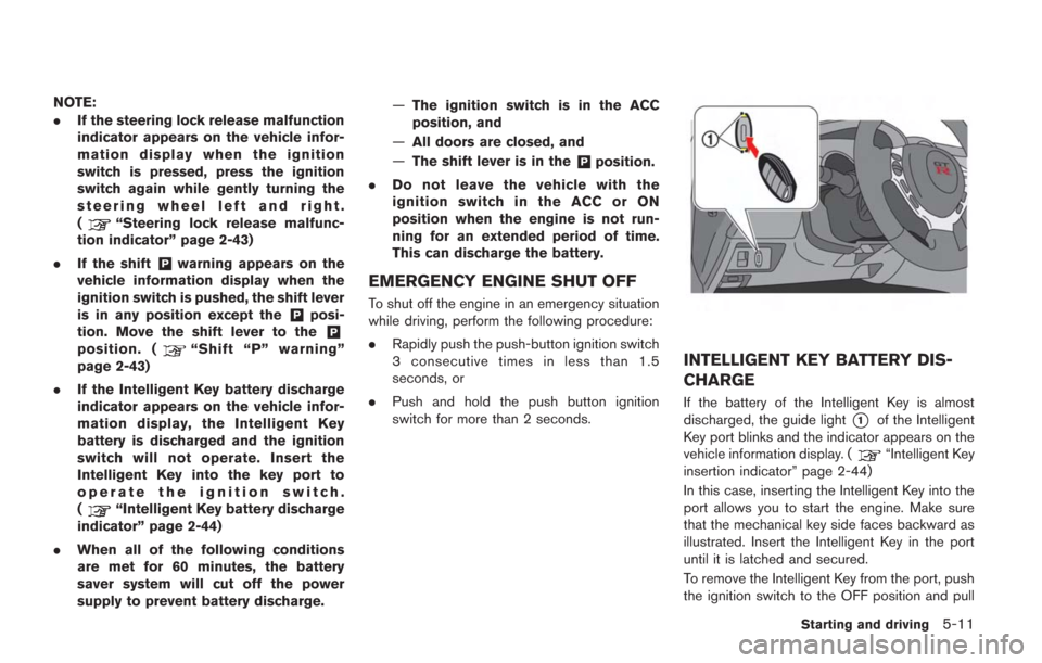
If the battery of the Intelligent Key is almost
discharged, the guide light
*1of the Intelligent
Key port blinks and the indicator appears on the
vehicle information display. (
“Intelligent Key
insertion indicator” page 2-44)
In this case, inserting the Intelligent Key into the
port allows you to start the engine. Make sure
that the mechanical key side faces backward as
illustrated. Insert the Intelligent Key in the port
until it is latched and secured.
To remove the Intelligent Key from the port, push
the ignition switch to the OFF position and pull
Starting and driving5-11
Page 226 of 354
Vehicle Dynamic Control (VDC)
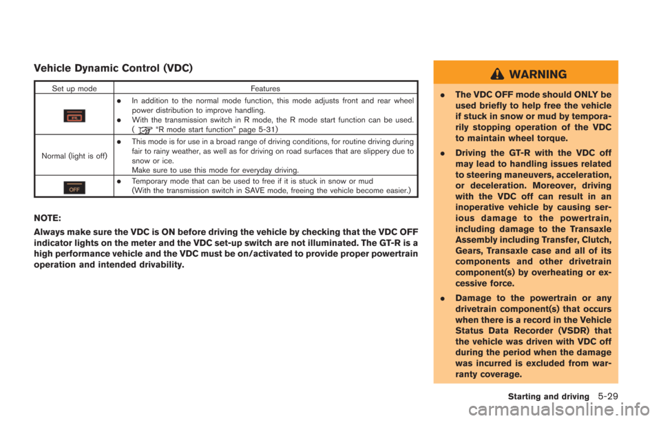
Set up modeFeatures
.In addition to the normal mode function, this mode adjusts front and rear wheel
power distribution to improve handling.
.With the transmission switch in R mode, the R mode start function can be used.
(“R mode start function” page 5-31)
Normal (light is off)
.This mode is for use in a broad range of driving conditions, for routine driving during
fair to rainy weather, as well as for driving on road surfaces that are slippery due to
snow or ice.
Make sure to use this mode for everyday driving.
.Temporary mode that can be used to free if it is stuck in snow or mud
(With the transmission switch in SAVE mode, freeing the vehicle become easier.)
NOTE:
Always make sure the VDC is ON before driving the vehicle by checking that the VDC OFF
indicator lights on the meter and the VDC set-up switch are not illuminated. The GT-R is a
high performance vehicle and the VDC must be on/activated to provide proper powertrain
operation and intended drivability.
WARNING
. The VDC OFF mode should ONLY be
used briefly to help free the vehicle
if stuck in snow or mud by tempora-
rily stopping operation of the VDC
to maintain wheel torque.
. Driving the GT-R with the VDC off
may lead to handling issues related
to steering maneuvers, acceleration,
or deceleration. Moreover, driving
with the VDC off can result in an
inoperative vehicle by causing ser-
ious damage to the powertrain,
including damage to the Transaxle
Assembly including Transfer, Clutch,
Gears, Transaxle case and all of its
components and other drivetrain
component(s) by overheating or ex-
cessive force.
. Damage to the powertrain or any
drivetrain component(s) that occurs
when there is a record in the Vehicle
Status Data Recorder (VSDR) that
the vehicle was driven with VDC off
during the period when the damage
was incurred is excluded from war-
ranty coverage.
Starting and driving5-29
Page 243 of 354
5-46Starting and driving
wheel gently touches the curb.
.HEADED UPHILL OR DOWNHILL, NO
CURB:
*3
Turn the wheels toward the side of the
road so the vehicle will move away from
the center of the road if it moves.
4. Push the ignition switch to the LOCK position.
The GT-R uses brake pad materials that have
high metallic content. The brake pad material
helps maintain braking performance in a wide
range of weather and driving conditions.
For the first 3,000 - 6,000 miles (5,000 -
10,000 km) of the vehicle’s service life, and for
the first 3,000 - 6,000 miles (5,000 - 10,000
km) after a brake replacement, the brake pad to
brake rotor clearance is very small. When
parking, apply the parking brake and move the
shift lever to the
&Pposition. Idle the engine for
more than 20 seconds without depressing the
brake pedal. This allows the brake pads to move
away from the rotor so the pad does not contact
the rotor.
Additionally, the brakes must be dry before
parking the vehicle after driving on wet roads or
after washing the vehicle. If the roads are wet,
lightly apply the brakes for a short distance
before parking the vehicle to dry the brakes.
After washing the vehicle, dry the brakes by driving on a dry road for a few miles and apply
the brakes normally based on traffic and road
conditions.
The metallic brake pads and brake disc rotor
may rust together when the brakes are not
applied:
.
If the vehicle is not idled for 20 seconds
without the brakes applied, or if the brakes
are applied when the vehicle is shut off, the
rotor and pads can rust together, even when
the brake pads are dry.
. If the brakes are wet when the vehicle is
parked and the parking brake is applied for a
long time.
Contact a GT-R certified NISSAN dealer if the
brake pads and brake rotor have rusted
together.
WARNING
If the engine is not running or is turned
off while driving, the power assist for
the steering will not work. Steering will
be harder to operate.
The power assisted steering uses a hydraulic
pump, driven by the engine, to assist steering.
If the engine stops or the drive belt breaks, you
will still have control of the vehicle. However,
much greater steering effort is needed, espe-
cially in sharp turns and at low speeds.
POWER STEERING
Page 246 of 354
The Vehicle Dynamic Control (VDC) system
uses various sensors to monitor driver inputs
and vehicle motion. Under certain driving con-
ditions, the VDC system helps to perform the
following functions.
.Controls brake pressure to reduce wheel
slip on one slipping drive wheel so power is
transferred to a non slipping drive wheel on
the same axle.
. Controls brake pressure and engine output
to reduce drive wheel slip based on vehicle
speed (traction control function) .
. Controls brake pressure at individual wheels
and engine output to help the driver maintain
control of the vehicle in the following
conditions:
— understeer (vehicle tends to not follow
the steered path despite increased
steering input)
— oversteer (vehicle tends to spin due to certain road or driving conditions) .
The VDC system can help the driver to maintain
control of the vehicle, but it cannot prevent loss
of vehicle control in all driving situations.
When the VDC system operates, the VDC
warning light
in the instrument panel flashes
so note the following: .
The road may be slippery or the system may
determine some action is required to help
keep the vehicle on the steered path.
. You may feel a pulsation in the brake pedal
and hear a noise or vibration from under the
hood. This is normal and indicates that the
VDC system is working properly.
. Adjust your speed and driving to the road
conditions.
. The VDC mode can be changed using the
VDC setup switch. (
“VDC, transmis-
sion and suspension setup switches” page
5-24)
(
“Vehicle Dynamic Control (VDC) warning
light” page 2-31,“Vehicle Dynamic Con-
trol (VDC) off indicator light” page 2-32)
If a malfunction occurs in the system, the VDC
warning light
illuminates in the instrument
panel. The VDC system automatically turns off.
The VDC setup switch is used to turn off the
VDC system. The VDC off indicator
illuminates to indicate the VDC system is off.
When the VDC setup switch is used to turn off
the system, the VDC system still operates to
prevent one drive wheel from slipping by
transferring power to a non slipping drive wheel.
The VDC warning light
flashes if this
occurs. All other VDC functions are off and the VDC warning light
will not flash. The VDC
system is automatically reset to on when the
ignition switch is placed in the off position then
back to the on position.
(
“Vehicle Dynamic Control (VDC) warning
light” page 2-31,“Vehicle Dynamic Con-
trol (VDC) off indicator light” page 2-32)
The computer has a built-in diagnostic feature
that tests the system each time you start the
engine and move the vehicle forward or in
reverse at a slow speed. When the self-test
occurs, you may hear a “clunk” noise and/or feel
a pulsation in the brake pedal. This is normal and
is not an indication of a malfunction.
WARNING
. The VDC system is designed to help
the driver maintain stability but
does not prevent accidents due to
abrupt steering operation at high
speeds or by careless or dangerous
driving techniques. Reduce vehicle
speed and be especially careful
when driving and cornering on slip-
pery surfaces and always drive care-
fully.
. Do not modify the vehicle’s suspen-
sion. If suspension parts such as
Starting and driving5-49
VEHICLE DYNAMIC CONTROL (VDC)
SYSTEM
Page 247 of 354
5-50Starting and driving
shock absorbers, struts, springs,
stabilizer bars, bushings and
wheels are not NISSAN approved
or are extremely deteriorated, the
VDC system may not operate prop-
erly. This could adversely affect
vehicle handling performance, and
the VDC warning light
may
illuminate.
. If brake related parts such as brake
pads, rotors and calipers are not
standard equipment or are extre-
mely deteriorated, the VDC system
may not operate properly and the
VDC warning light
may illumi-
nate.
. If engine control related parts are
not standard equipment or are ex-
tremely deteriorated, the VDC warn-
ing light
may illuminate.
. When driving on extremely inclined
surfaces such as higher banked
corners, the VDC system may not
operate properly and the VDC warn-
ing light
may illuminate. Do not
drive on these types of roads.
. When driving on an unstable sur-
face such as a turntable, ferry, elevator or ramp, the VDC warning
light
may illuminate. This is not
a malfunction. Restart the engine
after driving onto a stable surface.
. If wheels or tires other than the
those recommended are used, the
VDC system may not operate prop-
erly and the VDC warning light
may illuminate.
. The VDC system is not a substitute
for winter tires or tire chains on a
snow covered road.
NOTE:
. Always make sure the VDC is ON
before driving the vehicle by checking
that the VDC OFF indicator lights on
the meter and the VDC set-up switch
are not illuminated.
The GT-R is a high performance vehicle
and the VDC must be on/activated to
provide proper powertrain operation
and intended drivability.
WARNING
.The VDC OFF mode should ONLY be
used briefly to help free the vehicle
if stuck in snow or mud by tempora-
rily stopping operation of the VDC
to maintain wheel torque.
. Driving the GT-R with the VDC off
may lead to handling issues related
to steering maneuvers, acceleration,
or deceleration. Moreover, driving
with the VDC off can result in an
inoperative vehicle by causing ser-
ious damage to the powertrain,
including damage to the Transaxle
Assembly including Transfer, Clutch,
Gears, Transaxle case and all of its
components and other drivetrain
component(s) by overheating or ex-
cessive force.
. Damage to the powertrain or any
drivetrain component(s) that occurs
when there is a record in the Vehicle
Status Data Recorder (VSDR) that
the vehicle was driven with VDC off
during the period when the damage
was incurred is excluded from war-
ranty coverage.
Page 258 of 354
electrical systems (light, heater, air condi-
tioner, etc.).
3. Remove the battery cover. Cover the battery with a firmly wrung out moist cloth to reduce
explosion hazard.
4. Connect jumper cables in the sequence as illustrated (
*1?*2?*3?*4).
If the battery is disconnected or dis-
charged, the steering wheel will lock
and cannot be turned. Supply power
using jumper cables before pushing
the ignition switch and disengaging
the steering lock.
CAUTION
. Always connect positive (+) to posi-
tive (+) and negative (−) to body
ground (as illustrated) , not to the
battery.
. Make sure that the jumper cables
do not touch moving parts in the
engine compartment and that
clamps do not contact any other
metal.
5. Start the engine of the booster vehicle
*A
and let it run for a few minutes. 6. Keep the engine speed of the booster
vehicle
*Aat about 2,000 rpm, and start
the engine of the vehicle being jump started
*B.
NOTE:
Do not keep the starter motor engaged
for more than 10 seconds. If the engine
does not start right away, push the
ignition switch to the OFF position and
wait 10 seconds before trying again.
7. After starting your engine, carefully discon- nect the negative cable and then the positive
cable (
*4?*3?*2?*1).
8. Be sure to dispose of the cloth used to cover the vent holes as it may be contami-
nated with corrosive acid.
9. Put the battery cover on.
NOTE:
If the clamp clip is difficult to connect to
the battery terminal, remove the cowl top
cover to make it easier. (
“Removing
the cowl top cover” page 8-9)
Do not attempt to start the engine by pushing.
NOTICE
Your NISSAN cannot be push-started or
tow-started. Attempting to do so may
cause transmission damage.
In case of emergency6-7
PUSH STARTING
Page 272 of 354
8 Maintenance and do-it-yourself
Maintenance requirement ....................................................... 8-3Scheduled maintenance ................................................... 8-3
General maintenance ........................................................ 8-3
Where to go for service ................................................... 8-3
General maintenance .............................................................. 8-4 Explanation of maintenance items ................................. 8-4
Maintenance precautions ....................................................... 8-6
Engine compartment check locations ................................. 8-8 Removing the cowl top cover ......................................... 8-9
Engine cooling system ......................................................... 8-10
Checking engine coolant level ..................................... 8-11
Changing engine coolant .............................................. 8-12
Engine oil ........................................................................\
........ 8-12
Checking engine oil level .............................................. 8-12
Changing engine oil and filter ...................................... 8-13
Transmission oil ..................................................................... 8-14
Power steering fluid .............................................................. 8-14
Brake fluid ........................................................................\
....... 8-15
Window washer fluid ........................................................... 8-16
Battery ........................................................................\
.............. 8-17
Precautions ....................................................................... 8-17
Fluid level check .............................................................. 8-17
Jump starting .................................................................... 8-19 Drive belts ........................................................................\
...... 8-19
Spark plugs ........................................................................\
.... 8-20
Replacing spark plugs ................................................. 8-20
Air cleaner ........................................................................\
...... 8-20
Windshield wiper blades .................................................... 8-21 Cleaning ........................................................................\
.. 8-21
Replacing the wiper blades ....................................... 8-22
Brakes ........................................................................\
............. 8-23 Self-adjusting brakes ................................................... 8-23
Brake pad wear warning ............................................. 8-23
High performance brake system ............................... 8-23
Replacing the brake pads ........................................... 8-23
Fuses ........................................................................\
............... 8-24
Engine compartment .................................................... 8-24
Passenger compartment ............................................. 8-25
Intelligent Key battery replacement .................................. 8-27
Lights ........................................................................\
............... 8-29 Headlights ....................................................................... 8-30Exterior and interior lights ........................................... 8-30
Wheels and tires .................................................................. 8-32
Tire pressure .................................................................. 8-32
Tire and loading information label ............................ 8-34
Checking the tire pressure ......................................... 8-35